

Page 1
InternationalShipKit
G009027
1
2
RT1200Trencher
ModelNo.131-2883
Introduction
ReadtheOperator’sManualforyourmachineandthe
attachmentscarefullytolearnhowtooperateandmaintain
yourproductproperlyandtoavoidinjuryandproduct
damage.Youareresponsibleforoperatingtheproduct
properlyandsafely.
YoumaycontactTorodirectlyatwww.Toro.comforproduct
safetyandoperationtrainingmaterials,accessoryinformation,
helpndingadealer,ortoregisteryourproduct.
Wheneveryouneedservice,genuineToroparts,oradditional
information,contactanAuthorizedToroServiceDealer
orToroCustomerServiceandhavethemodelandserial
numbersofyourproductready.
Important:Thismachinewasmanufacturedaccording
totheappropriateregulatorystandardsineffectatthe
timeofmanufacture.Modifyingthismachineinany
waymaycauseittobeoutofcompliancewiththose
standardsandwiththeinstructionsinthis
Man ual.
onlybyanAuthorizedToroServiceDealer.
Modicationstothismachineshouldbemade
Operator’ s
FormNo.3396-716RevA
InstallationInstructions
CAUTION
Thismachineproducessoundlevelsthatcancause
hearinglossthroughextendedperiodsofexposure.
Wearhearingprotectionwhenoperatingthis
machine.
Theuseofprotectiveequipmentforeyes,ears,hands,feet,
andheadisrecommended.
Figure2
1.Wearsafetyglasses.
2.Wearhearingprotection.
Contents
Thismanualidentiespotentialhazardsandhassafety
messagesidentiedbythesafetyalertsymbol(Figure1),
whichsignalsahazardthatmaycauseseriousinjuryordeath
ifyoudonotfollowtherecommendedprecautions.
Figure1
1.Safetyalertsymbol
Thismanualuses2wordstohighlightinformation.
Importantcallsattentiontospecialmechanicalinformation
andNoteemphasizesgeneralinformationworthyofspecial
attention.
Introduction..................................................................1
ConguringtheMachineforShipping...............................2
PreparingtheMachine.............................................2
PreparingtoRemovetheROPS.................................2
RemovingtheROPS................................................7
AssemblingtheMachineforShipping........................9
PreparingtoMovetheMachine................................11
PreparingtheMachinefortheCustomer...........................12
PreparingtoMovetheMachine................................12
PreparingtheMachine............................................13
RemovingtheShippingConguration
Components......................................................13
InstallingtheROPS................................................16
InstallingtheRearFendersandtheRearControl
Cover................................................................18
InstallingtheDashPanelandConsole
Panel.................................................................19
InstallingtheTurbocharger-ExhaustPipe..................21
InstallingtheMuferExtensionandRain
Cap...................................................................25
SwitchingntheBatteryandInstallingtheSide
Panels...............................................................25
©2015—TheT oro®Company
8111LyndaleAvenueSouth
Bloomington,MN55420
Registeratwww.T oro.com.
OriginalInstructions(EN)
PrintedintheUSA
AllRightsReserved
*3396-716*A
Page 2
Conguringthe
MachineforShipping
LooseParts
Description
Shippingplate
Hearingprotector1Wearpersonalprotectiveequipment.
Quantity
1Installtheshippingplate.
PreparingtheMachine
Lifting-equipmentcapacity:408kg(900lb)minimum
1.Ensurethatthemachinetiltislevelandthetilt-lockout
pinisinstalled;refertotheOperator’sManualforthe
machine.
2.Movethemachinetoalevelsurfacethatisbelowthe
liftingequipmentwiththespeciedliftcapacity.
3.Lowerallattachments,stoptheengine,andremove
thekeyfromtheKEYSWITCH;refertotheOperator’ s
Manualforthemachine.
4.Allowtheexhaustsystemtocoolcompletely.
PreparingtoRemovethe ROPS
Use
RemovingtheSidePanelsand
DisconnectingtheBattery
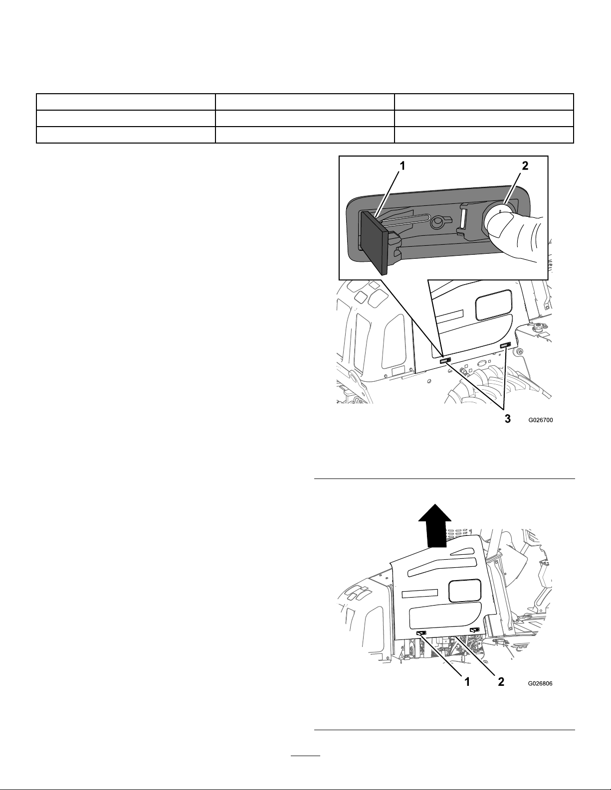
1.Pressinthebuttonportionofeachlatch—thepartof
thelatchincludingthelockcylinder(Figure3).
Figure3
1.Latchlever
2.Latchbutton
2.Liftthepanelupandawayfromthemachine(Figure4).
3.Side-panellatch
Figure4
1.Latch
2
2.Sidepanel
Page 3
3.Repeatsteps1and2forthesidepanelattheotherside
ofthemachine.
4.Placebothsidepanelsintotheshippingcontainer.
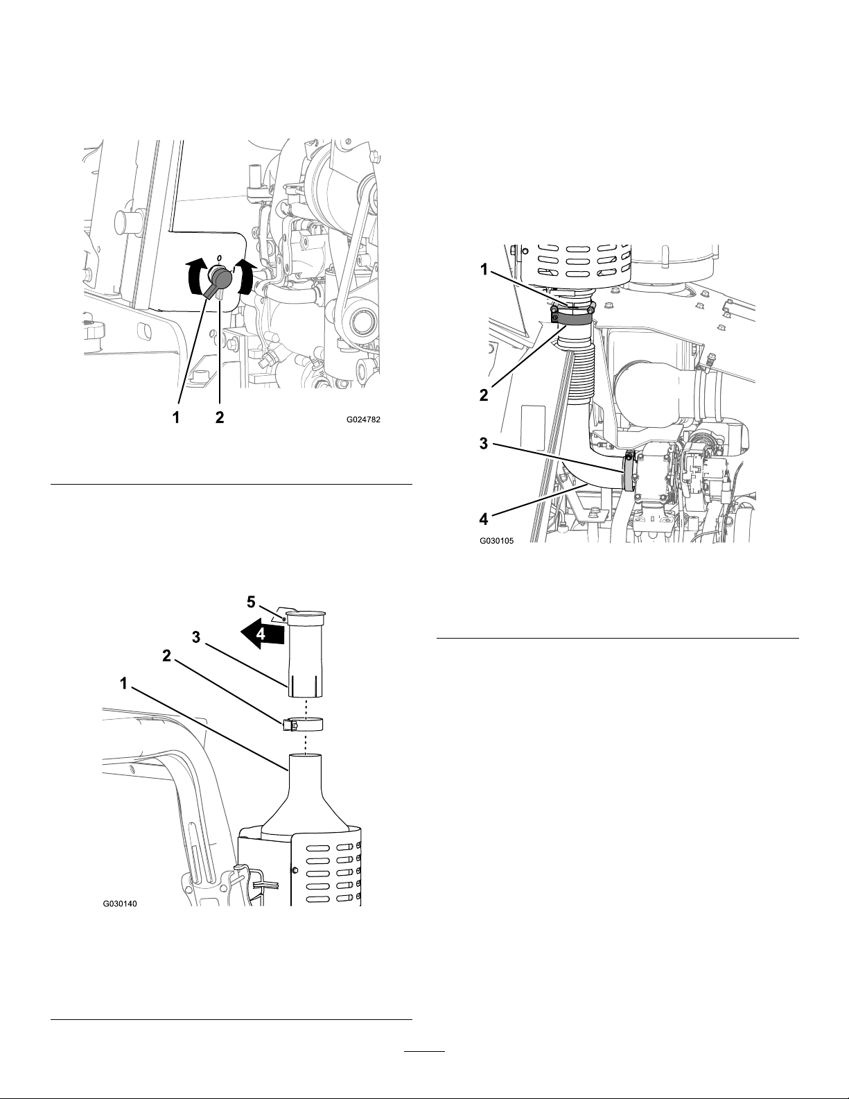
5.RotatetheBATTERYDISCONNECTswitch
counterclockwisetotheOFFposition(Figure5).
Figure5
2.Removetheextension,raincap,andclampfromthe
mufer(Figure6).
3.Placeextension,raincap,andclampintotheshipping
container.
RemovingtheTurbocharger-Exhaust
Pipe
1.Removethebandclampandthelowerguillotineclamp
thatsecurethemufertotheturbocharger-exhaust
pipe(Figure7).
1.BATTERYONposition2.BATTERYOFFposition
RemovingtheMuferExtensionand
RainCap
1.Loosentheclampthatsecuresthemuferextension
andraincaptotheoutletpipeofthemufer(Figure6).
Figure7
1.Guillotineclamp
2.Bandclamp4.Turbocharger-exhaust
3.Flangeclamp
pipe
2.Removetheangeclampthatsecurestheangeofthe
turbocharger-exhaustpipetotheoutletangeofthe
turbocharger(Figure7).
3.Movetheturbocharger-exhaustpipedownuntilthe
alignmentpinsofthemufer-inletpipecleartheslots
intheturbocharger-exhaustpipe(Figure8).
Important:Donotbendordamagethepleated
sectionoftheturbocharger-exhaustpipewhile
removingthepipetothemachine.
Figure6
1.Mufer-outletpipe4.Inboardofthemachine
2.Clamp5.Pivot(raincap)
3.Muferextensionandrain
cap
3
Page 4
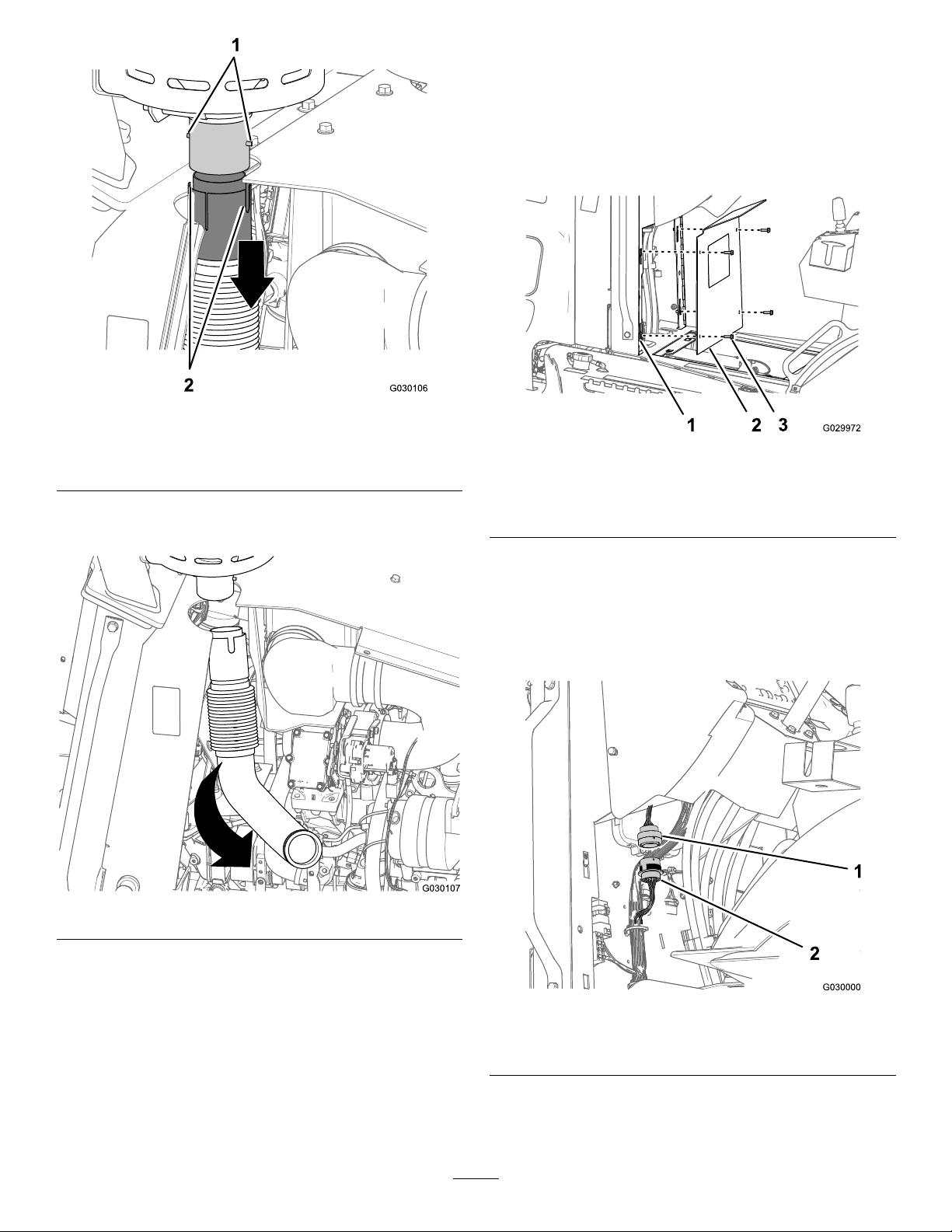
Figure8
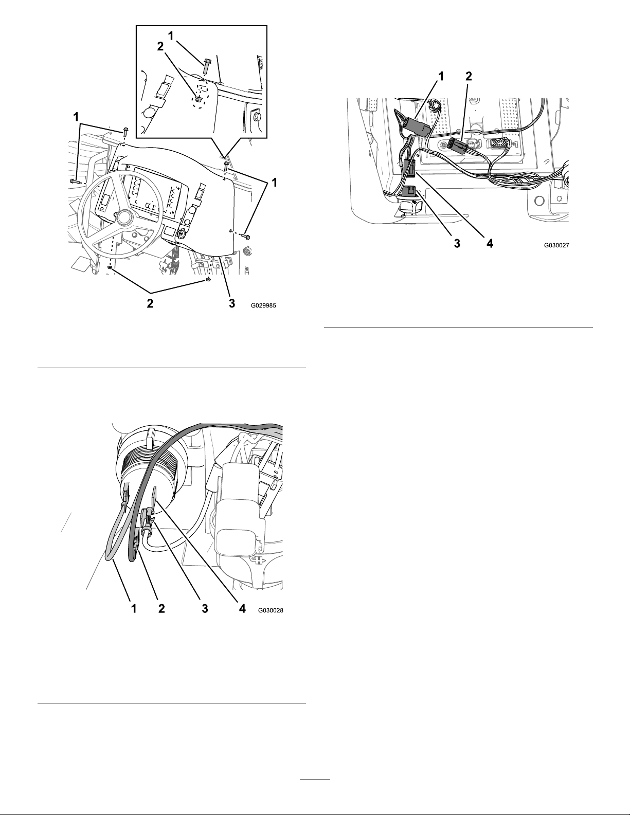
RemovingtheConsolePanelandthe
DashPanel
RemovingtheConsolePanel
1.Removethe4ange-headbolts(5/16x1inch)that
securetheconsolepaneltotheframeoftheconsole
(Figure10).
1.Alignmentpin(mufer-inlet
pipe)
2.Slots
(turbocharger-exhaust
pipe)
4.Removetheturbocharger-exhaustpipefromthe
machine(Figure9).
Figure10
1.Consoleframe3.Flange-headbolts(5/16x
1inch)
2.Consolepanel
2.Removethepanelfromthemachine(Figure10).
RemovingtheDashPanel
1.Disconnectthe23-pinconnectorofthedashwiring
harnessfromthe23-socketconnectorforthemachine
wiringharness(Figure11)
Figure9
5.Placetheturbocharger-exhaustpipe,bandclamp,
guillotineclamp,andangeclampintotheshipping
container.
Figure11
1.23-pinconnector(dash
wiringharness)
2.23-socketconnector
(machinewiringharness)
2.Removethe4angebolts(8x30mm)and2ange
locknuts(8mm)thatsecurethedashpaneltotheframe
oftheconsole(Figure12).
4
Page 5
5.Removethe6-socketconnectorofthewiringharness
forthemachinefromtheconnectorforthestarter
switch(Figure14).
Figure14
Figure12
1.Flangebolt(8x30mm)
2.Flangelocknut(8mm)
3.Dashassembly
3.Removethepiggybackterminalofthewiringharness
forthemachinefromthebladeterminalofthe
auxiliary-powerport(Figure13).
1.6-pinconnector(wiring
harnessforthemachine)
2.6-socketconnector(dash
harness)
3.Starter-switchconnector
4.6-socketconnector(wiring
harnessforthemachine)
6.Removethe6-pinconnectorofthewiringharnessfor
themachinefromthe6-socketconnectorofthedash
harness(Figure14).
7.Carefullyremovethedashpanelfromtheconsole
(Figure12).
Note:Setasidethedashpanel,angebolts,and
locknutsforassemblyinAssemblingtheMachinefor
Shipping(page9).
Figure13
1.Bluewire(dashharness)3.Piggybackterminal(wiring
2.Socketterminal—black
(ground)wire(dash
harness)
harnessforthemachine)
4.Bladeterminal
(auxiliary-powerport)
4.Removethesocketterminalfortheblackwireofthe
dashharnessfromthepiggybackterminalofthewiring
harnessforthemachine(Figure13)
5
Page 6
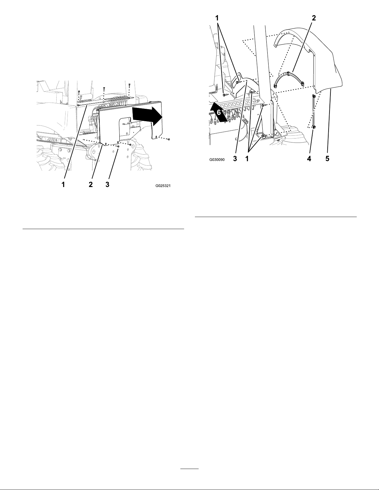
RemovingtheRearControlCoverand
RearFenders
RemovingtheRearControlCover
1.Removethe6ange-headbolt(12x30mm)that
securetherearcontrolcovertotherearbulkheadof
themachine(Figure15).
Figure16
Figure15
1.Bulkhead
2.Rearcoverplate
3.Flange-headbolt(12x30
mm)
2.Removethecontrolcoverfromthemachine.
Note:Setasidethecontrolcoverandange-head
boltsforassemblyinAssemblingtheMachinefor
Shipping(page9).
RemovingtheRearFenders
1.Removethe5ange-headbolts(10x30mm)and2
reinforcementplates(withtheattachednutclips)that
securethefendertothechassisofthemachine(Figure
16).
Note:Haveanotherpersonsupporttherearfender
whileyouremovethemountinghardware.
1.Flange-headbolts(10x
30mm)
2.Curvedreinforcement
plateandclipnuts
3.Fendermount
4.Straightreinforcement
plateandclipnuts
5.Fender
6.Frontofthemachine
2.Removethefenderfromthemachine.
3.Repeatsteps1and2fortherearfenderattheother
sideofthemachine.
Note:Setasidethefenders,reinforcementplates
(withtheattachedclipnuts),andange-headbolts
forassemblyinAssemblingtheMachineforShipping
(page9).
6
Page 7
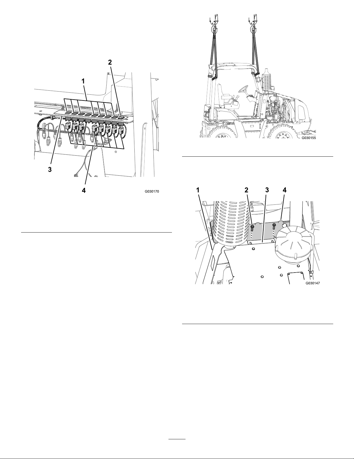
DisconnectingtheAuxiliary-Control
PanelWiring
1.Attheauxiliary-controlpanel,removethe10-socket
connectorattheendofthemain-wiringharnessfrom
the10-pinconnectorforthetiltswitch(Figure17).
Figure18
2.Removethe2ange-headbolts(12x40mm)that
securethehoodplate,ROPS-mountingplate,leftcowl
panel,andrightcowlpanel(Figure19)
Figure17
1.Plugs3.Auxiliary-controlpanel
2.Tiltswitch4.10-socketconnectors
(main-wiringharness)
2.Removethe7remaining10-socketconnectorsofthe
main-wiringharnessfromthe7rocker-switchplugsin
theauxiliary-controlpanel(Figure17).
RemovingtheROPS
Lifting-equipmentcapacity:408kg(900lb)minimum
AdditionalEquipment:hand-operatedwinch
1.SupporttheROPSframeandmuferwithlifting
equipmenthavingaminimumliftcapacityof408kg
(900lb)asshowninFigure18.
Note:TheROPSframeandmuferisweighted
towardtherear.YouwillneedtotilttheROPSframe
andmufertoremovetheROPS.Wheneverpossible,
use2piecesofliftingequipmenttolifttheROPSframe
andmufer.
Figure19
1.Leftcowlpanel3.Hood-plateange
2.Flange-headbolt(12x40
mm)
4.ROPS-mountingplate
3.Removethe2ange-headbolts(16x50mm)
and2angelocknuts(16mm)thatsecurethe
ROPS-mountingplatetotheframeoftheconsole
(Figure20).
Note:Ifyouhavedifcultyremovingthebolts,
theROPSframetubesareundertension.Usea
hand-operatedwinchtopullthefrontROPStube(s)
towardthereartube(s)torelievesheeringpressure
fromthebolts.
Note:Discardthe2ange-headbolts(16x50mm)
and2angelocknuts(16mm).
7
Page 8
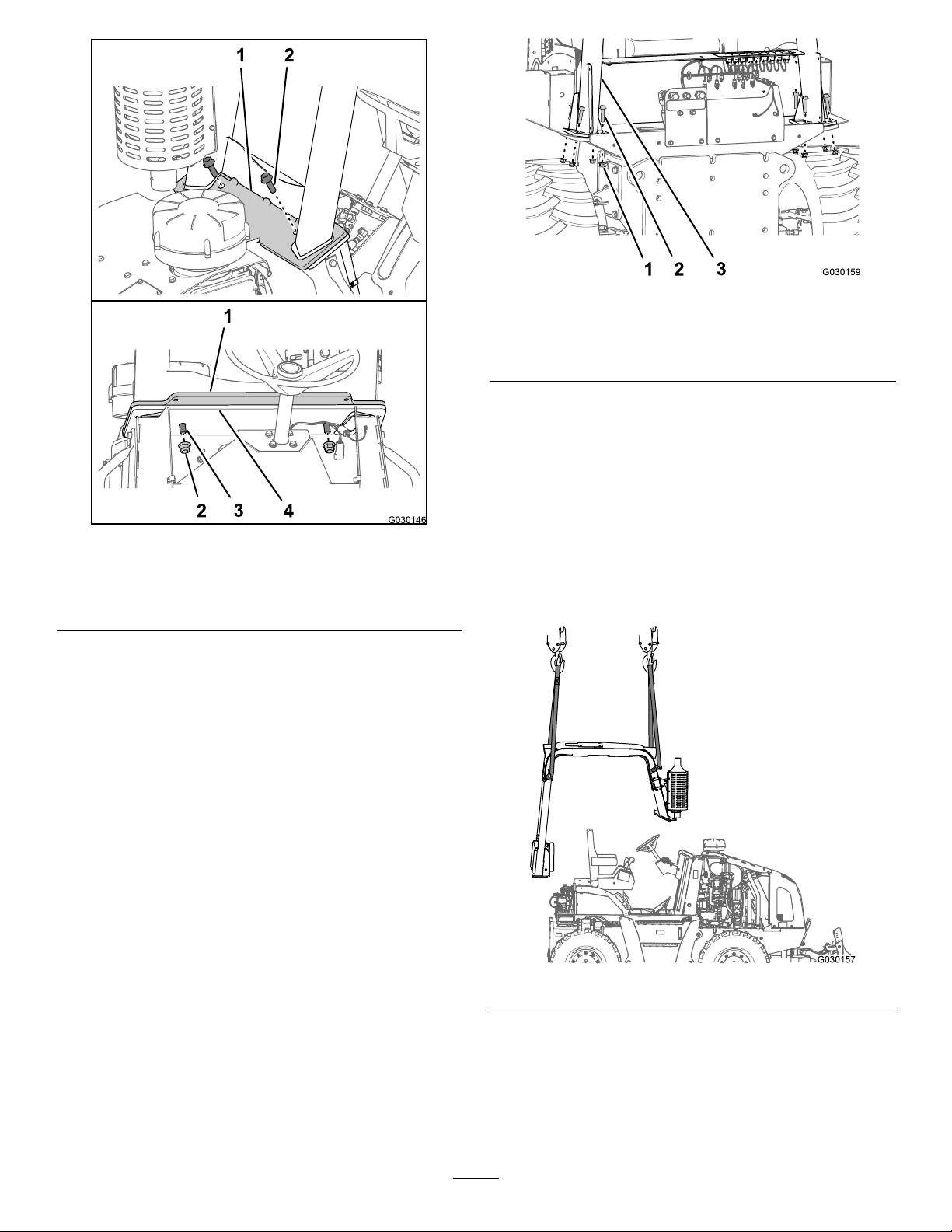
Figure20
1.ROPS-mountingplate3.Flange-headbolts(16x
50mm)
2.Flangelocknuts(16mm)4.Consoleframe
4.AttherearframetubesfortheROPS,removethe8
ange-headbolts(16x70mm)and8angelocknuts
(16mm)thatsecuretheROPStubestothechassisof
themachine(Figure21).
Figure21
1.Flangelocknuts(16mm)3.ROPStube
2.Flange-headbolts(16x
70mm)
5.Usingtheliftingequipment,raisethebackoftheROPS
slightly.
6.Usingtheliftingequipment,movetheROPSrearward
andupuntiltheROPS-mountingplateclearsthehood
plateandcowlpanels(Figure19).
Note:PayattentiontotheROPS-mountingplateasit
separatesfromthehoodplateandcowlpanels,andas
themountingplateclearsthesteeringwheel.
7.LifttheROPSandmuferandremovetheROPSfrom
themachine(Figure22).
Note:Ifyouhavedifcultyremovingthebolts,
theROPSframetubesareundertension.Usea
hand-operatedwinchtopulltheROPStubestogether
torelievesheeringpressurefromthebolts.
Note:Discardthe8ange-headbolts(16x70mm)
and8angelocknuts(16mm).
Figure22
8.MovetheROPSandmufertotheshippingcontainer.
8
Page 9
AssemblingtheMachinefor Shipping
InstallingtheShippingPlate
1.Aligntheshippingplatebetweentheangeofthehood
plate,leftcowlpanel,andrightcowlpanel(Figure23).
AssemblingtheDashPaneland
ConsolePaneltotheMachine
AssemblingtheDashPanel
1.Alignthedashpaneltotheconsole(Figure24).
Figure24
1.Dashwiringharness3.Machinewiringharness
2.Dashpanel
Figure23
1.Hood-plateange3.Cowlpanel
2.Shippingplate4.Flange-headbolt(12x40
mm)
2.Assembletheshippingplate,hoodplateandcowl
panels(Figure23)withthe2ange-headbolt(12x
40mm)thatyouremovedinstep2inRemovingthe
ROPS(page7).
3.Tightentheange-headbolttoashippingtorqueof40
to50N-m(30to37ft-lb).
2.Connectthesocketterminalfortheblackwireof
thedashharnessontothepiggybackterminalofthe
wiringharnessforthemachine;refertoFigure13in
RemovingtheDashPanel(page4).
3.Connectthepiggybackterminalofthewiringharness
forthemachineontotheopenbladeterminalofthe
auxiliary-powerport;refertoFigure13inRemoving
theDashPanel(page4).
4.Connectthe6-socketconnectorofthewiringharness
forthemachineontotheconnectorforthestarter
switch;refertoFigure14inRemovingtheDashPanel
(page4).
5.Connectthe6-pinconnectorofthewiringharness
forthemachineintothe6-socketconnectorofthe
dashharness;refertoFigure14inRemovingtheDash
Panel(page4).
6.Aligntheholesinthedashpanelwithholesinthe
consoleframeandtheshippingplate(Figure25).
9
Page 10

Figure25
AssemblingtheRearFendersandRear
ControlCovertotheMachine
AssemblingtheRearFenders
1.Aligntheholesinthestraightreinforcementplate(with
theattachedclipnuts)thatyouremovedinstep1of
RemovingtheRearFenders(page6)withtherear2
holesintherearfender(Figure26).
1.Flangebolts(8x30mm)
2.Flangelocknuts(8mm)4.Consoleframe
3.Dashpanel
7.Assemblethedashpaneltotheconsoleandthe
shippingplate(Figure25)withthe4angebolts(8x
30mm)and2angelocknuts(8mm)thatyouremoved
instep2ofRemovingtheDashPanel(page4)
8.Tightentheange-headboltsandlocknutsatthefront
ofthedashuntiltheendoftheboltisushwiththe
lockingportionofthelocknut(Figure25)
9.Tightentheange-headboltsatthesideofthedash
paneltoashippingtorqueof120to140N-cm(108
to132in-lb).
10.Connectthe23-pinconnectorofthedashwiring
harnesstothe23-socketconnectorofthemachine
wiringharness;refertoFigure11inRemovingthe
DashPanel(page4).
AssemblingtheConsolePanel
1.Aligntheholesintheconsolepanelwiththeholes
intheframeoftheconsole;refertoFigure10in
RemovingtheDashPanel(page4).
Figure26
1.Fendermount
2.Frontofthemachine5.Straightreinforcement
3.Curvedreinforcement
plateandclipnuts
4.Rearfender
plateandclipnuts
6.Flange-headbolts(10x
30mm)
2.Assemblethestraightreinforcementplate(withthe
attachedclipnuts)tothefenderwiththe2ange-head
bolts(10x30mm)thatyouremovedinstep1of
RemovingtheRearFenders(page6)andtightenthe
boltssecurely(Figure26).
3.Alignthecurvedreinforcementplate(withtheattached
clipnuts)thatyouremovedinstep1ofRemovingthe
RearFenders(page6)withtheforward,insideholesof
therearfender(Figure26).
2.Assemblethepaneltotheconsolewiththe4
ange-headbolts(5/16x1inch)thatyouremovedin
step1ofRemovingtheDashPanel(page4).
3.Tightentheange-headboltstoashippingtorqueof
989to2540N-cm(88to123in-lb).
4.Alignthefender,plate,andclipnutwiththeholeinthe
fendermountoftheoperator’splatform(Figure26).
Note:Haveanotherpersonsupporttherearfender
whileyouinstallthemountinghardware.
5.Assemblethefender,plate,andclipnuttothefender
mountwith3ange-headbolts(10x30mm)thatyou
removedinstep1ofRemovingtheRearFenders(page
6).
6.Tightentheange-headboltstoashippingtorqueof
24to29N-cm(17to21ft-lb).
10
Page 11

7.Repeatsteps1through6fortherearfenderatthe
G009027
1
2
othersideofthemachine.
AssemblingtheRearControlCover
1.Assemble3ange-headbolts(12x30mm)thatyou
removedinstep1inRemovingtheRearFenders(page
6)intothetop3clipnutsattheholesintherearcontrol
coverandtightensecurely(Figure27).
Figure28
1.BATTERYONposition2.BATTERYOFFposition
WearingPersonalProtectiveEquipment
Figure27
1.Flange-headbolts(12x
30mm)
2.Rearcontrolcover
2.Aligntheholesintherearcontrolcoverwiththeholes
intherearplatformframe(Figure27).
3.Assembletherearcontrolcovertotherearplatform
frame(Figure27)withthe3ange-headbolts(12x30
mm)thatyouremovedinstep1inDisconnectingthe
Auxiliary-ControlPanelWiring(page7).
4.Tightenthe3ange-headboltstoashippingtorqueof
40to50N-m(30to36in-lb).
3.Rearplatformframe
PreparingtoMovetheMachine
ConnectingtheBattery
RotatetheBATTERYDISCONNECTswitchtotheONposition
(Figure28).
CAUTION
Thismachineproducessoundlevelsthatcancause
hearinglossthroughextendedperiodsofexposure.
Wearhearingprotectionwhenoperatingthis
machine.
Theuseofprotectiveequipmentforeyes,ears,hands,feet,
andheadisrecommended.
Figure29
1.Wearsafetyglasses.
1.Wearthesuppliedhearingprotectorwhenmovingthe
machineintotheshippingcontainer.
2.Whennishedmovingthemachineintotheshipping
container,attachthehearingprotectortothesteering
wheelofthemachine.
2.Wearhearingprotection.
DisconnectingtheBattery
RotatetheBATTERYDISCONNECTswitchtotheOFFposition
(Figure28).
11
Page 12

PreparingtheMachine
G009027
1
2
fortheCustomer
LooseParts
Description
Hearingprotector1Wearpersonalprotectiveequipment.
ROPSandmuferassembly
Flange-headbolt(16x50mm)
Flangelocknut(16mm)
Flange-headbolts(16x70mm)
Shim1.52mm(0.06inch)
Shim0.76mm(0.03inch)
Muferextensionandraincap
Clamp
Sidepanel(left)
Sidepanel(right)
PreparingtoMovetheMachine
ConnectingtheBattery
RotatetheBATTERYDISCONNECTswitchtotheONposition
(Figure30).
Quantity
1
2
10
8
3Aligntheturbocharger-exhaustpipe.
1Aligntheturbocharger-exhaustpipe.
1
1
1Installthesidepanels.
1Installthesidepanels.
AligntheROPStothemachine.
AssembletheROPStothemachine.
AssembletheROPStothemachine.
AssembletheROPStothemachine.
Installthemuferextensionandraincap.
Installthemuferextensionandraincap.
WearingPersonalProtectiveEquipment
CAUTION
Thismachineproducessoundlevelsthatcancause
hearinglossthroughextendedperiodsofexposure.
Wearhearingprotectionwhenoperatingthis
machine.
Use
Theuseofprotectiveequipmentforeyes,ears,hands,feet,
andheadisrecommended.
Figure31
1.Wearsafetyglasses.
2.Wearhearingprotection.
1.Removethehearingprotectorfromthesteeringwheel.
Figure30
1.BATTERYONposition2.BATTERYOFFposition
2.Wearthesuppliedhearingprotectorwhenmovingthe
machinefromtheshippingcontainer.
12
Page 13

PreparingtheMachine
Lifting-equipmentcapacity:408kg(900lb)minimum
1.Ensurethatthemachinetiltislevelandthetilt-lockout
pinisinstalled;refertotheOperator’sManualforthe
machine.
2.Movethemachinetoalevelsurfacethatisbelowthe
liftingequipmentwiththespeciedliftcapacity.
3.Lowerallattachments,stoptheengine,andremove
thekeyfromtheKEYSWITCH;refertotheOperator’ s
Manualforthemachine.
4.Allowtheenginetocoolcompletely .
RemovingtheShipping
CongurationComponents
RemovingtheRearControlCoverand
RearFenders
RemovingtheRearControlCover
RemovingtheRearFenders
1.Removethe3ange-headbolts(10x30mm)that
securetherearfenderandcurvedreinforcementplate
(withtheattachedclipnuts)tothefendermount,and
removethefender(Figure33).
Note:Haveanotherpersonsupporttherearfender
whileyouremovethemountinghardware.
1.Removethe3ange-headbolts(12x30mm)fromthe
clipnutsatthetop3holesintherearcontrolcover
(Figure32).
Figure32
Figure33
1.Fendermount
2.Frontofthemachine5.Straightreinforcement
3.Curvedreinforcement
plateandclipnuts
4.Rearfender
plateandclipnuts
6.Flange-headbolts(10x
30mm)
2.Removethe2ange-headbolts(10x30mm)and
straightreinforcementplate(withtheattachedclip
nuts)fromtherear2holesintherearfender(Figure
33).
3.Repeatsteps1and2fortherearfenderattheother
sideofthemachine.
4.Settheange-headbolts,reinforcementplates(with
theattachedclipnuts),andfendersforinstallationin
InstallingtheRearFenders(page18).
1.Flange-headbolts(12x
30mm)
2.Rearcontrolcover
3.Rearplatformframe
2.Removethe3ange-headbolts(12x30mm)that
securetherearcontrolcovertotherearplatformframe,
andremovethecoverfromthemachine(Figure32).
3.Setasidethecoverandange-headboltsforinstallation
inInstallingtheRearControlCover(page19).
13
Page 14

RemovingtheConsolePanelandthe
DashPanel
RemovingtheConsolePanel
1.Removethe4ange-headbolts(5/16x1inch)that
securetheconsolepaneltotheframeoftheconsole
(Figure34).
Figure34
2.Removethe4angebolts(8x30mm)and2ange
locknuts(8mm)thatsecurethedashpaneltotheframe
oftheconsole(Figure36).
1.Consoleframe3.Flange-headbolts(5/16x
1inch)
2.Consolepanel
2.Removethepanelfromthemachine(Figure34).
3.Setasidethepanelandange-headboltsforinstallation
inInstallingtheConsolePanel(page21).
RemovingtheDashPanel
1.Disconnectthe23-pinconnectorofthedashwiring
harnessfromthe23-socketconnectorforthemachine
wiringharness(Figure35)
Figure36
1.Flangebolts(8x30mm)
2.Flangelocknuts(8mm)4.Consoleframe
3.Dashpanel
3.Liftupthedashpaneluntilyoucanaccesstheelectrical
connectorsattheforwardsideofthepanel.
4.Removethepiggybackterminalofthewiringharness
forthemachinefromthebladeterminalofthe
auxiliary-powerport(Figure37).
1.23-pinconnector(dash
wiringharness)
Figure35
2.23-socketconnector
(machinewiringharness)
Figure37
1.Bluewire(dashharness)3.Piggybackterminal(wiring
2.Socketterminal—black
(ground)wire(dash
harness)
14
harnessforthemachine)
4.Bladeterminal
(auxiliary-powerport)
Page 15

5.Removethesocketterminalfortheblackwireofthe
dashharnessfromthepiggybackterminalofthewiring
harnessforthemachine(Figure37)
6.Removethe6-socketconnectorofthewiringharness
forthemachinefromtheconnectorforthestarter
switch(Figure38).
Figure38
RemovingtheShippingPlate
1.Removethe2ange-headbolt(12x40mm)that
securetheshippingplate,hoodplate,leftcowlpanel,
andrightcowlpanel(Figure40).
1.6-pinconnector(wiring
harnessforthemachine)
2.6-socketconnector(dash
harness)
3.Starter-switchconnector
4.6-socketconnector(wiring
harnessforthemachine)
7.Removethe6-pinconnectorofthewiringharnessfor
themachinefromthe6-socketconnectorofthedash
harness(Figure38).
8.Carefullyremovethedashpanelfromtheconsole
(Figure39).
Figure40
1.Flange-headbolt(12x40
mm)
2.Hood-plateange4.Shippingplate
3.Shippingplate
2.Movetheshippingplateoutwarduntiltheplateclears
theangeofthehoodplate,andremovetheshipping
platefromthemachine(Figure40).
Note:Retaintheange-headboltsforinstallation
inAssemblingtheROPStotheMachine(page17).
Discardtheshippingplate.
Figure39
1.Dashwiringharness3.Machinewiringharness
2.Dashpanel
9.Settheange-headbolts,locknuts,anddashpanelfor
installationinInstallingtheDashPanel(page19).
15
Page 16

InstallingtheROPS
AligningtheROPStotheMachine
Lifting-equipmentcapacity:408kg(900lb)minimum
Customerprovidedtool:hand-operatedwinch.
1.SupporttheROPSframeandmuferwithlifting
equipmenthavingaminimumliftcapacityof408kg
(900lb)asshowninFigure41.
Note:TheROPSframeandmuferisweighted
towardtherear.YouwillneedtotilttheROPSframe
andmufertoinstalltheROPS.Wheneverpossible,
use2piecesofliftingequipmenttolifttheROPSframe
andmufer.
Figure42
4.TipthefrontoftheROPSdowntoaligntheforward
ROPSplatebetweentheangeofthehoodplate,left
cowlpanel,andrightcowlpanel(Figure42andFigure
43).
Figure41
2.Usingtheliftingequipment,carefullyremovethe
ROPSandmuferfromtheshippingcontainerand
aligntheROPSabovethemachine(Figure41).
3.MovetheROPSforwardanddownuntilthe
ROPS-mountingplatetheclearssteeringwheel(Figure
42).
Figure43
1.Flange(hoodplate)3.ROPSplate
2.Leftandrightcowlpanels
16
Page 17

5.Atthebackofthemachine,checktheclearance
betweentherearbulkheadpaneloftheROPSandthe
wiringharnessofthemachine(Figure44)
Figure44
1.Flangefortherearframe
tube(ROPS)
2.ROPSmounts(chassis)4.Wiringharness(machine)
3.Rearbulkheadpanel
(ROPS)
6.Usingtheliftingequipment,carefullymovetheROPS
forwardanddownuntiltheholesinthehoodplate
andcowlsarealignedwiththeholesintheROPSplate
(Figure43).
7.AligntheangesattherearframetubesfortheROPS
withtheROPSmountsforthechassisofthemachine
(Figure44).
AssemblingtheROPStotheMachine
1.AssembletheROPSplatetotheframeoftheconsole
withthe2ange-headbolts(16x50mm)and2ange
locknuts(16mm)fromtheshippingkit,andtighten
theboltsandnutsbyhand(Figure45).
Figure45
1.ROPS-mountingplate3.Flange-headbolts(16x
50mm)
2.Flangelocknuts(16mm)4.Consoleframe
2.Applyacoatofmedium-grade,thread-locking
compoundtothethreadsofthe2ange-headbolts(12
x40mm)thatyouremovedinstep1inRemovingthe
ShippingPlate(page15).
3.Assemblethe2ange-headbolts(12x40mm)through
theholesintheangeofthehoodpanel,ROPSplate,
leftcowlpanel,andrightcowlpanel,andtightenthe
boltsandnutsbyhand(Figure46).
17
Page 18

Figure46
1.Leftcowlpanel3.Hood-plateange
2.Flange-headbolt(12x40
mm)
4.ROPS-mountingplate
4.Aligntheholesintheangeattherearframetubefor
theROPSwiththeholesintheROPSmountforthe
chassisofthemachine(Figure47).
Note:Ifyouhavedifcultyaligningtheholes,usea
hand-operatedwinchbetweentherearROPStubeand
afrontROPStubetopulltherearROPStubeforward
andaligntheholes.Usethehand-operatedwinch
betweentherearROPStubestopullthetubesinward
toaligntheholes(Figure47).
DescriptionTorquevalue
Flange-headbolts(16x50
mm)andangelocknuts
(16mm)—ROPSplateand
consoleframe(Figure45)
Flange-headbolts(12x40
mm)—hoodplate,ROPS
plate,leftandrightcowlpanel
(Figure46)
Flange-headbolts(16x70
mm)andangelocknuts(16
mm)—rearROPStubesand
chassis(Figure47)
319to400N-m(235to295
ft-lb)
80to10N-m(59to73ft-lb)
319to400N-m(235to295
ft-lb)
InstallingtheRearFenders andtheRearControlCover
InstallingtheRearFenders
1.Applyacoatofmedium-grade,thread-locking
compoundtothethreadsofthe10ange-headbolts
(10x30mm)thatyouremovedinsteps1and3of
RemovingtheRearFenders(page13).
2.Aligntheholesintherearfenderwiththeholesinthe
fendermountofthechassisandangeoftheROPS
tube(Figure48).
Note:Haveanotherpersonsupporttherearfender
whileyouinstallthemountinghardware.
Figure47
1.Flangelocknuts(16mm)3.ROPStube
2.Flange-headbolts(16x
70mm)
5.AssembletherearROPStubetothechassiswith4
ange-headbolts(16x70mm)and4angelocknuts
(16mm),andtightenbyhand(Figure47).
6.Repeatsteps4and5totherearROPStubeattheother
sideofthemachine.
7.Torquetheboltsandnutsasindicatedinthetablethat
follows:
1.Flange-headbolts(10x
30mm)
2.Curvedreinforcement
plateandclipnuts
3.Fendermount
18
Figure48
4.Straightreinforcement
plateandclipnuts
5.Fender
6.Frontofthemachine
Page 19

3.Alignthenutclipsonthereinforcementplateswiththe
holesinthefender(Figure48).
4.Assemblethefender,reinforcementplates,andnut
clipstothemachine(Figure48)withthe5ange-head
bolts(10x30mm).
5.Torquetheange-headboltsto47to57N-m(34to
42ft-lb).
6.Repeatsteps2through5fortherearfenderatthe
othersideofthemachine.
InstallingtheRearControlCover
1.Atthebackofthemachine,connectthe10-socket
connectorattheendofthemain-wiringharnessinto
the10-pinconnectorofthetiltswitch(Figure49).
Figure50
1.Bulkhead
2.Rearcoverplate
3.Flange-headbolt(12x30
mm)
5.Assembletherearcontrolcoverwiththeholesinthe
rearbulkhead(Figure50)withthe6ange-headbolt
(12x30mm).
Figure49
1.Plugs3.Auxiliary-controlpanel
2.Tiltswitch4.10-socketconnector
(main-wiringharness)
2.Assemblethe7remaining10-socketconnectorsinto
the7rocker-switchplugsintheauxiliary-controlpanel
(Figure49)
3.Applyacoatofmedium-grade,thread-locking
compoundtothethreadsofthe6ange-headbolts
(12x30mm)thatyouremovedinsteps1and2in
RemovingtheRearControlCover(page13).
4.Aligntheholesintherearcontrolcoverwiththeholes
intherearbulkheadofthemachine(Figure50).
6.Torquetheange-headboltto80to10N-m(59to
73ft-lb).
InstallingtheDashPaneland ConsolePanel
InstallingtheDashPanel
1.Alignthedashpaneltotheconsole(Figure48).
Figure51
1.Dashwiringharness3.Machinewiringharness
2.Dashpanel
2.Connectthesocketterminalfortheblackwireofthe
dashharnessontothepiggybackterminalofthewiring
harnessforthemachine(Figure52).
19
Page 20

Figure52
G030030
7.Aligntheholesinthedashpanelwithholesinthe
consoleframe(Figure54).
1.Bluewire(dashharness)3.Piggybackterminal(wiring
2.Socketterminal—black
(ground)wire(dash
harness)
harnessforthemachine)
4.Bladeterminal
(auxiliary-powerport)
3.Connectthepiggybackterminalofthewiringharness
forthemachineontotheopenbladeterminalofthe
auxiliary-powerport(Figure52).
4.Connectthe6-socketconnectorofthewiringharness
forthemachineontotheconnectorforthestarter
switch(Figure53).
Figure54
8.Assemblethedashpaneltotheconsole(Figure55)
withthe4angebolts(8x30mm)and2ange
locknuts(8mm).
Figure53
1.6-pinconnector(wiring
harnessforthemachine)
2.6-socketconnector(dash
harness)
3.Starter-switchconnector
4.6-socketconnector(wiring
harnessforthemachine)
5.Connectthe6-pinconnectorofthewiringharnessfor
themachineintothe6-socketconnectorofthedash
harness(Figure53).
6.Applyacoatofmedium-grade,thread-locking
compoundtothethreadsofthe4angebolts(8x30
mm)thatyouremovedinstep2ofRemovingtheDash
Panel(page14).
Figure55
1.Flangebolt(8x30mm)
2.Flangelocknut(8mm)
3.Dashassembly
9.Tightentheange-headboltsandlocknutstoanal
torqueof120to140N-cm(108to132in-lb).
20
Page 21

InstallingtheConsolePanel
1.Connectthe23-pinconnectorofthedashwiring
harnesstothe23-socketconnectorofthemachine
wiringharness(Figure56).
Figure56
Installingthe Turbocharger-ExhaustPipe
AssemblingtheTurbocharger-Exhaust
PipeontotheMachine
1.Aligntheturbocharger-exhaustpipe(fromtheshipping
kit)throughthenotchesintherightcowlpaneland
hoodpanelofthemachine(Figure58).
Important:Donotbendordamagethepleated
sectionoftheturbocharger-exhaustpipewhile
assemblingthepipetothemachine.
1.23-pinconnector(dash
wiringharness)
2.Applymedium-grade,thread-lockingcompoundtothe
4ange-headbolts(5/16x1inch)thatyouremovedin
step1ofRemovingtheConsolePanel(page14).
3.Aligntheholesintheconsolepanelwiththeholesin
theframeoftheconsole(Figure57).
2.23-socketconnector
(machinewiringharness)
Figure57
Figure58
2.Aligntheslotsintheturbocharger-exhaustpipewith
thealignmentpinsofthemufer-inletpipeand
assembletheexhaustpipeontothemufer(Figure59).
1.Consoleframe3.Flange-headbolts(5/16x
1inch)
2.Consolepanel
4.Assemblethepaneltotheconsole(Figure57)withthe
4ange-headbolts(5/16x1inch).
5.Tightentheboltstoanaltorqueof1978to2542
N-cm(175to225in-lb).
21
Page 22

Figure59
1.Alignmentpins
(mufer-inletpipe)
2.Slots
(turbocharger-exhaust
pipe)
3.Aligntheangesoftheturbocharger-exhaustpipeand
theoutletangeoftheturbocharger,assemblethe
angeclampovertheanges,andtightentheclampto
closet(Figure60).
Note:Whentheangesoftheturbochargeroutlet
andtheturbocharger-exhaustpipearealigned,the2
alignmentpinsforthemufer-inletpipeshouldhave
3.2mm(1/8inch)orgreaterclearancefromtheclosed
endofthe2slotsintheturbocharger-exhaustpipe.
4.Assemblethebandclamp(fromtheshippingkit)
belowthe2alignmentpinsofthemufer-inletpipe
andtightentheclamptocloset(Figure61).
Figure61
1.Guillotineclamp3.Alignmentpin(mufer-inlet
pipe)
2.Bandclamp
5.Assembletheguillotineclamp(fromtheshippingkit)
abovethe2alignmentpinsofthemufer-inletpipe
andtightentheclamptocloset(Figure61).
AligningtheTurbocharger-Exhaust
Pipe
MeasuringtheBellows
1.Turbocharger-exhaust
2.Flangeclamp
1.Atthefrontsideofthebellowsofthe
turbocharger-exhaustpipe,measurethedistancefrom
theupperedgeoftheupper-weldseamtothelower
edgeofthelower-weldseam.
Recordyourmeasurementhere:
Note:Ifyourfront-sidemeasurementislessthanor
greaterthan152.4mm(6inches)andthepleatsofthe
bellowsarenotverticallyaligned,performthestepsin
AligningtheMuferFronttoBack(page23).
Figure60
3.Turbochargeroutlet
pipe
22
Page 23

Figure62
AligningtheMuferFronttoBack
1.Loosenthe4ange-headbolts(8x120mm)and
angelocknuts(8mm)thatsecuretheexhaust-system
mounttotheROPStube(Figure63).
1.Upperedgeofthe
upper-weldseam
2.152.4mm(6inches)
3.Loweredgeofthe
lower-weldseam
2.Attherightsideofthebellows,measurethedistance
fromtheupperedgeoftheupper-weldseamtothe
loweredgeofthelower-weldseam.
Recordyourmeasurementhere:
Note:Ifyourrightsidemeasurementislessthanor
greaterthan152.4mm(6inches)andthepleatsofthe
bellowsarenotverticallyaligned,performthestepsin
AligningtheMuferLefttoRight(page24).
3.Ifthefrontandsidemeasurementsofweldseamsfor
thebellowsare152.4mm(6inches)andthepleatsof
thebellowsareverticallyaligned,skiptoSecuringthe
Turbocharger-ExhaustPipe(page24).
Figure63
1.ROPStube4.Shim0.76mm(0.03inch)
2.Exhaust-systemmount
3.Flange-headbolts(8x120
mm)—lowerpositions
5.Shim1.52mm(0.06inch)
2.Addshim(s)—fromtheshippingkitorremovethe
shim(s)totheexhaust-systemmountatthelower2
ange-headboltsasneededtoalignthepleatsofthe
bellows(Figure63).
Note:Changethetotalshimthicknessin0.76mm
(0.03inch)increments.
3.Torquetheange-headboltsandangelocknutsfor
theexhaust-systemmountto17to21N-m(23to29
ft-lb).
4.Measurethebellowsweld-seamdimensionandconrm
thatthepleatsofthebellowsarealignedstraight
(Figure62).
Note:Ifbellowsisnotaligned,repeatsteps1through
3untiltheweld-seamsmeasurementforthebellowsis
152.4mm(6inches)fronttobackandthepleatsofthe
bellowsarealignedstraight.
5.Iftheturbocharger-exhaustpipeisalignedlefttoright,
skiptoSecuringtheTurbocharger-ExhaustPipe(page
24).
23
Page 24

AligningtheMuferLefttoRight
1.Removethe6ange-headbolts(6x16mm)that
securetheheatshieldtotheexhaust-systemmountand
removetheheatshield(Figure64).
Figure64
1.Flange-headbolts(6x16
mm)
2.Clipnut(6mm)
3.Flange-headbolts(6x30
mm)
4.Muferstrap
5.Heatshield
2.Loosentheange-headbolts(6x30mm)thatsecure
themuferstrapstotheexhaust-systemmount(Figure
64).
3.Loosenthe2ange-headbolts(1/2x1inch)
andserratedangenuts(1/2inch)thatsecurethe
lower-mufersupporttotheexhaust-systemmount
(Figure65).
Figure65
1.Exhaust-systemmount
2.Flange-headbolts(1/2
x1inch)—lowermufer
support
3.Lower-mufersupport
4.Serratedangenuts(1/2
inch)
4.Movethemuferleftorrighttoalignthebellowsso
thattheweld-seammeasurementattheleftandright
sidesare152.4mm(6inches)andpleatsofthebellows
arealignedstraight(Figure65).
5.Tightenthe2ange-headbolts(1/2x1inch)
andserratedangenuts(1/2inch)thatsecurethe
lower-mufersupporttotheexhaust-systemmountto
91to113N-m(67to83ft-lb).
6.Tightentheange-headbolts(6x30mm)thatsecure
themuferstrapsto972to1198N-cm(86to106
in-lb).
7.Applyacoatofmedium-grade,thread-locking
compoundtothe6ange-headbolts(6x16mm)that
youremovedinstep1.
8.Assembletheheatshieldtoexhaust-systemmountwith
the6ange-headbolts(6x16mm)andtorquethe
boltsto972to1198N-cm(86to106in-lb).
9.Iftheturbocharger-exhaustpipeisalignedfrontto
back,skiptoSecuringtheTurbocharger-ExhaustPipe
(page24).
SecuringtheT urbocharger-ExhaustPipe
1.Tightenthenutoftheangeclampsecurely.
2.Tightentheangenutsoftheguillotineclampand
tightentheboltandnutofthebandclampsecurely.
24
Page 25

InstallingtheMuferExtension
SwitchingntheBatteryand
andRainCap
1.Aligntheraincapofthemuferextension(fromthe
shippingkit)totheoutletpipeofthemufersothat
thepivotfortheraincapisinboard(Figure66).
Note:Whentheraincapiscorrectlyalignedtothe
outletpipeofthemufer,exhaustfromthemufer
willblowoutwardandawayfromthemachine.
InstallingtheSidePanels
1.RotatetheBATTERYDISCONNECTswitchtotheON
position(Figure67).
Figure67
1.BATTERYONposition2.BATTERYOFFposition
Figure66
1.Mufer-outletpipe4.Inboardofthemachine
2.Clamp5.Pivot(raincap)
3.Muferextensionandrain
cap
2.Assemblethemuferextensionandraincaptothe
outletpipeofthemufer(Figure66).
Note:Ensurethattheendofthemufer-outletpipe
extendspasttheslotsinthemuferextension
3.Securethemuferextensionandraincap(Figure66)
withtheclamp76mm(3inch)fromtheshippingkit.
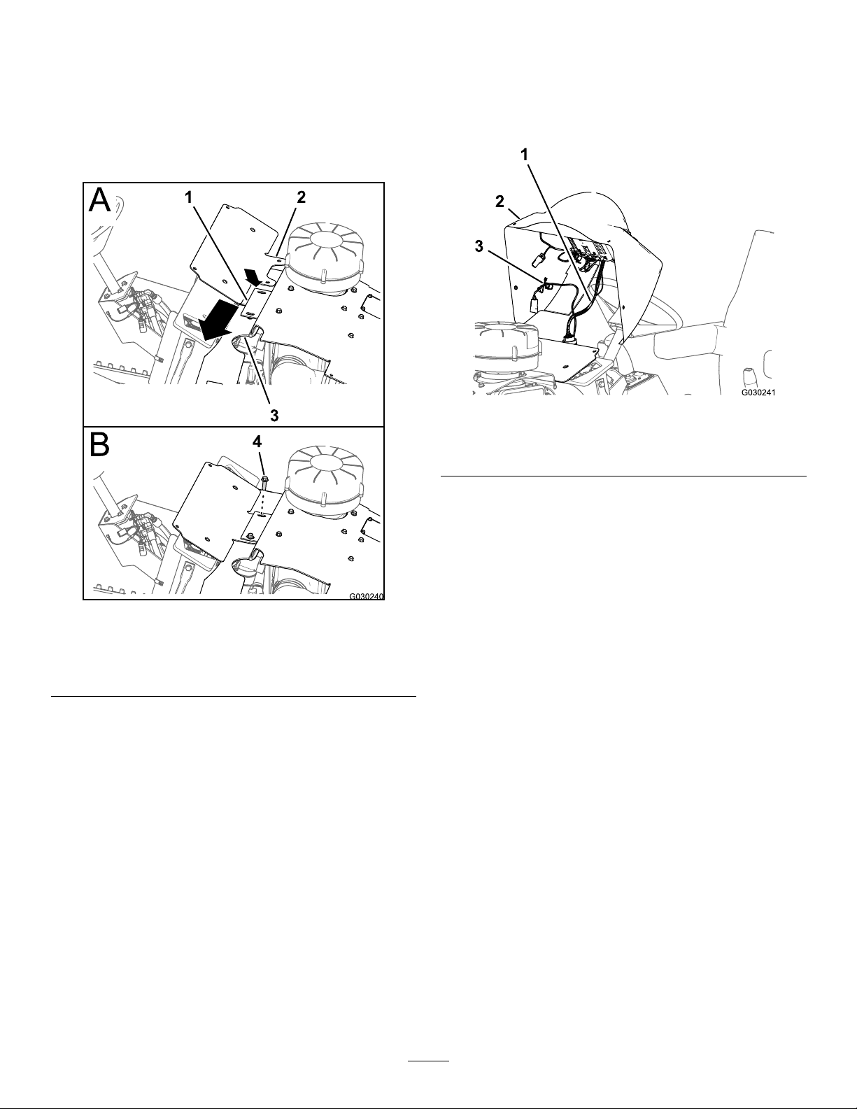
2.Alignthesidepanel(fromtheshippingkit)withthe
machineframe.
3.Alignthemountingboltatthetopofthesidepanel
withtheholeinthesupportangeofthehoodpanel
(Figure68).
Figure68
4.Applylightinwardpressureagainstthepanelat1of
thelatches.
5.Setthelatchbypushinginthelatchlever—thepartof
thelatchtotheleftofthelockcylinder(Figure69).
25
Page 26

Figure69
1.Latchlever
2.Latchbutton
3.Side-panellatch
6.Repeatsteps4and5attheotherlatch.
7.Repeatsteps2through6forthesidepanelattheother
sideofthemachine.
26
Page 27

Notes:
27
Page 28

 Loading...