

Page 1
FormNo.3396-283RevA
ColdStartKit
RT1200TractionUnit
ModelNo.131-2859
InstallationInstructions
WARNING
CALIFORNIA
Proposition65Warning
ThisproductcontainsachemicalorchemicalsknowntotheStateofCaliforniato
causecancer,birthdefects,orreproductiveharm.
Installation
1
PreparingtoInstalltheCold
StartKit
NoPartsRequired
PreparingtheMachine
1.Movethemachinetoalevelsurface,shutoffthe
engine,andremovethekeyfromthekeyswitch.
2.Allowtheengineandhydraulicsystemtocool.
RemovingtheSidePanelsand
DisconnectingtheBattery
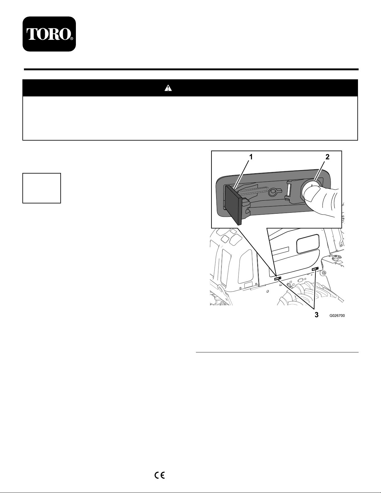
1.Pressinthebuttonportionofeachlatch—thepartof
thelatchincludingthelockcylinder(Figure1).
Figure1
1.Latchlever
2.Latchbutton
2.Liftthepanelupandawayfromthemachine(Figure2).
3.Side-panellatch
©2015—TheToro®Company
8111LyndaleAvenueSouth
Bloomington,MN55420
Registeratwww.T oro.com.
OriginalInstructions(EN)
PrintedintheUSA
AllRightsReserved
*3396-283*A
Page 2
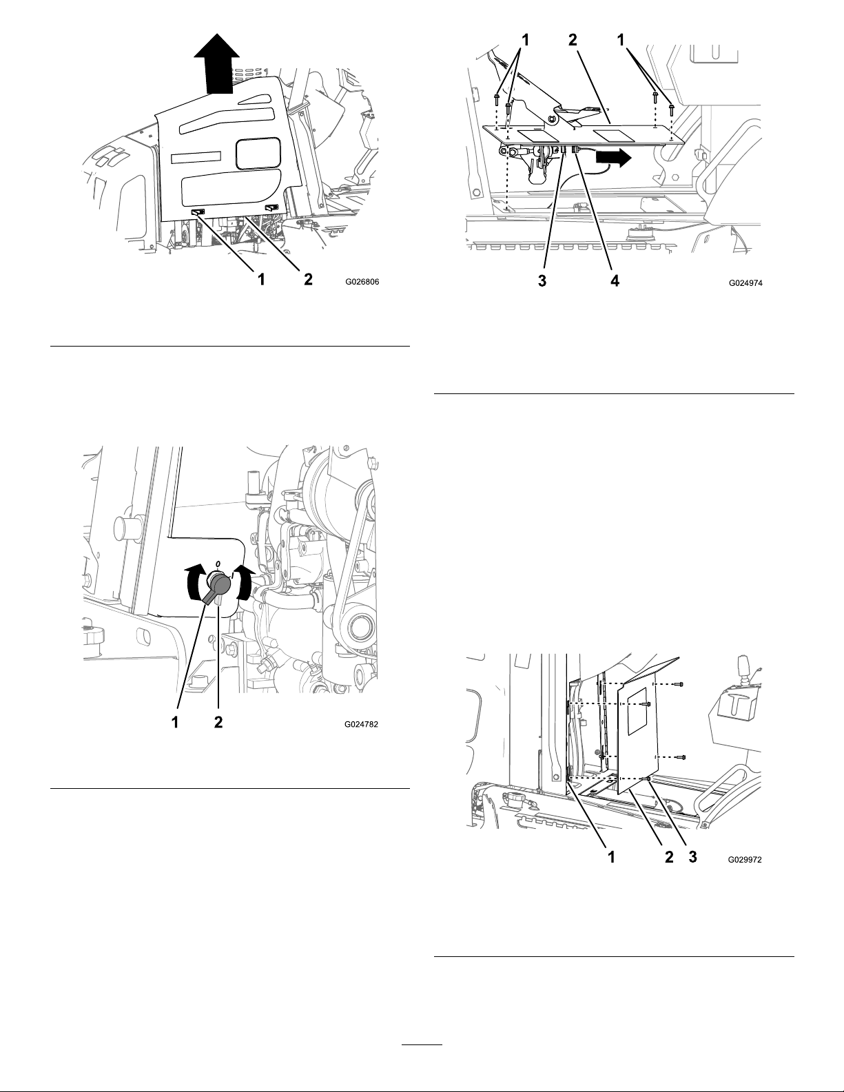
Figure2
Figure4
1.Latch
2.Sidepanel
3.Repeatsteps1and2forthesidepanelattheotherside
ofthemachine.
4.RotatetheBATTERYDISCONNECTswitch
counterclockwisetotheOFFposition(Figure3).
1.Flange-headbolts(5/16x
1inch)
2.Traction-pedalassembly4.6-socketconnector
3.6-pinconnector
(traction-pedalsensor)
(machineharness)
2.Removethecabletiesecuringthetraction-pedal
harness.
3.Disconnectthe6-socketconnectorofthemachine
harnessfromthe6-pinconnectorofthetraction-pedal
sensor(Figure4).
4.Removethetraction-pedalassemblyfromthemachine
(Figure4).
RemovingtheConsolePanel
1.Removethe4ange-headbolts(5/16x1inch)that
securetheconsolepaneltotheframeoftheconsole
(Figure5).
Figure3
1.BATTERYONposition2.BATTERYOFFposition
RemovingtheTraction-PedalAssembly
Removethetraction-pedalassemblyasfollows:
1.Removethe4ange-headbolts(5/16x1inch)that
securethattraction-pedalassemblytothechassisofthe
machine(Figure4).
Figure5
1.Flange-headbolts(5/16x
1inch)
2.Consolepanel
3.Consoleframe
2.Removetheconsolepanelfromthemachine(Figure5).
2
Page 3
RemovingtheTransmissionShield
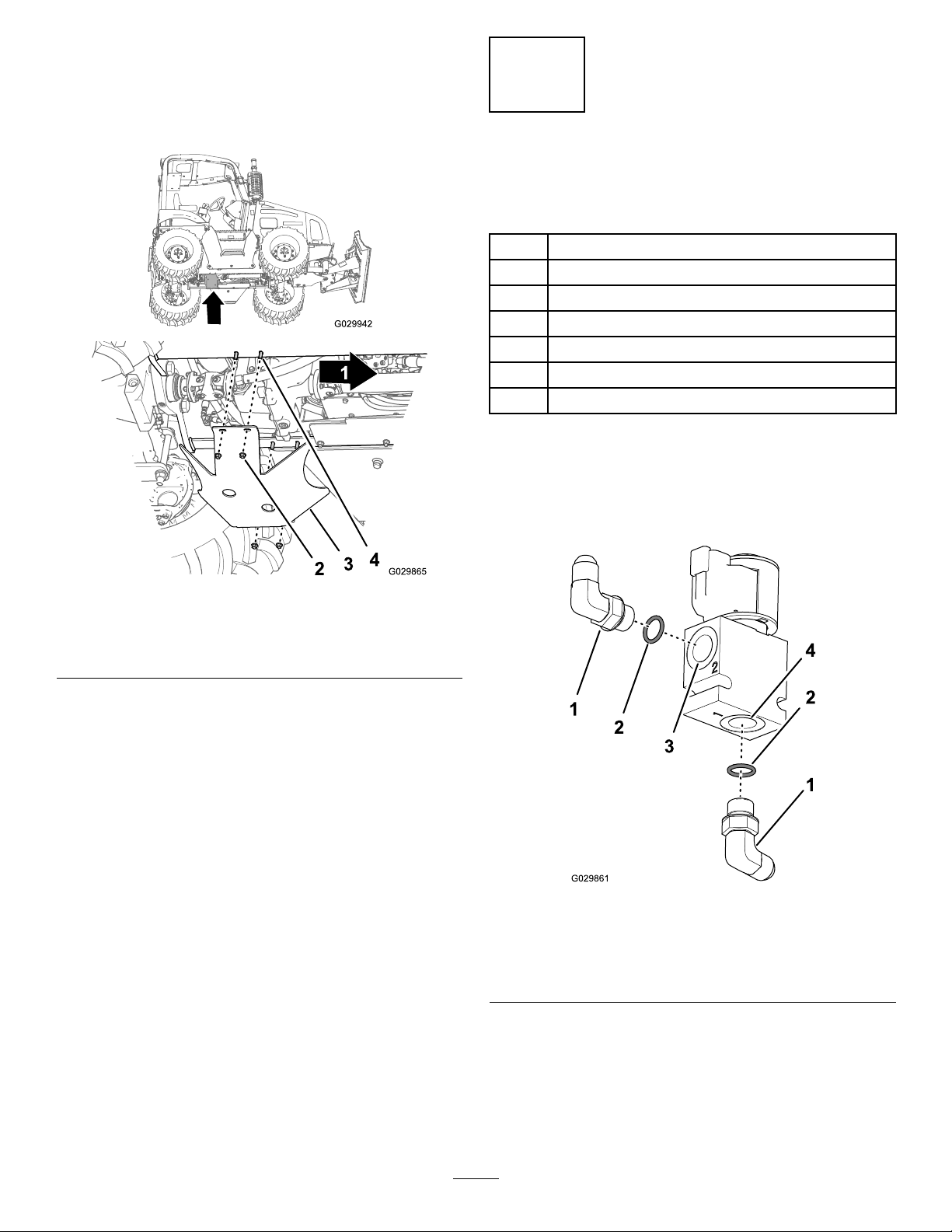
1.Removethe4angedlocknuts(1/2inch)from4
carriagebolts(1/2x1-1/2inch)thatsecurethe
transmissionshieldtotheframeofthemachine(Figure
6).
2
Assemblingthe2-Way
SolenoidValve
Partsneededforthisprocedure:
12-waysolenoidvalve
2
O-ring
2
90ºhydraulicttings
1Valve-mountplate
2
Carriagebolt(1/4x1-3/4inch)
2
Locknut(1/4inch)
2
Hose(1/4x16-1/4inch)
Procedure
1.Installthe2hydraulicttings(90°)andO-ringsinto
port1andport2ofthe2-waysolenoidvalveasshown
inFigure7.
Figure6
1.Frontofthemachine
2.Flangedlocknuts(1/2
inch)
2.Removethetransmissionshieldfromthemachine
(Figure6).
Note:Donotremovethecarriageboltsfromthe
frame.
3.Transmissionshield
4.Carriagebolts(1/2x1-1/2
inch)
Figure7
1.90ºhydraulicttings3.Port2(2-waysolenoid
valve)
2.O-ring4.Port1(2-waysolenoid
valve)
2.Assemblethe2-waysolenoidvalvetothevalve-mount
plate(Figure8)withthe2carriagebolts(1/4x1-3/4
inch)and2locknuts(1/4inch).
3
Page 4
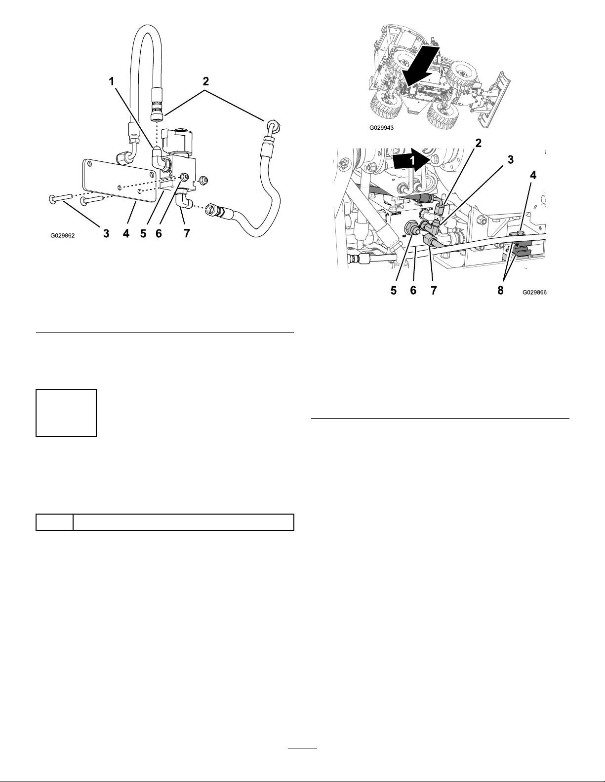
Figure8
1.90ºhydraulictting(port2)
2.Hoses(1/4x16-1/4inch)6.Locknut(1/4inch)
3.Carriagebolt(1/4x1-3/4
inch)
4.Valve-mountplate
3.Assemblethestraightttingsofthehoses(1/4x
16-1/4inch)ontothe90ºhydraulicttingsandtighten
thettingsbyhand(Figure8).
5.2-waysolenoidvalve
7.90ºhydraulictting(port1)
3
InstallingtheOriceInsertinto
theHIC-FanValve
Partsneededforthisprocedure:
1
Oriceinsert
Procedure
1.Loosenthebolt(5/16x1-1/2inch)thatsecuresthe
tubeforthefanmotorandtheclampblocks(Figure9).
Figure9
1.Frontofthemachine5.Straight-hydraulictting
2.Hydraulichose(signalport
XtoLShydraulicpump)
3.90°hydraulic
adapter—long(LS-pump
port)
4.Bolt(5/16x1-1/2inch)8.Clampblock
2.Removethetubenutforthefan-motortubeandthe
straight-hydraulicttingatportM2oftheHIC-fan
valve(Figure9).
Note:Packtheareaaroundthettingwithragsto
absorbthehydraulicuid.
3.Removethehydraulichosefromthe90ºhydraulic
adapterattheLS-pumpportoftheHIC-fanvalve
(Figure9).
4.Removethe90ºhydraulicadapterattheLS-pumpport
(Figure9).
Note:ChecktheO-ringforthe90ºhydraulicadapter,
replacetheO-ringifitisdamagedorworn
(M2port)
6.HIC-fanvalve
7.Tube(hydraulic—fan
motor)
5.ThreadtheoriceinsertintotheLS-pumpportofthe
HIC-fanvalveandtightenbyhand(Figure10).
4
Page 5
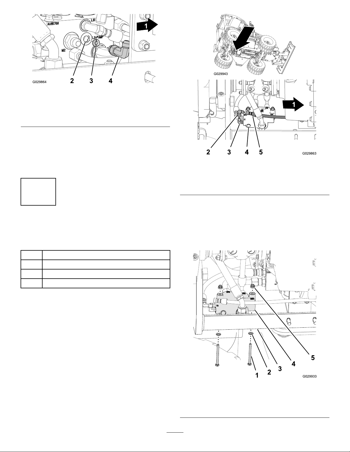
Figure10
1.Frontofthemachine3.Oriceinsert
2.LS-pumpport4.90ºhydraulic
adapter—long(LS-pump
port)
6.Threadthe90ºhydraulicadapterintotheLS-pump
portoftheHIC-fanvalve(Figure10).
Note:Youwilltightenthejamnutforthe90º
hydraulicadapter,installstraight-hydraulictting,and
installthefan-motortubeinlatersteps.
Figure11
1.Frontofthemachine
2.90°swiveltting5.Hose(hydraulicreturn)
3.90°hydraulictting(T-port)
4.Flow-dividervalve
4
Installingthe2-WaySolenoid
ValveandHoses
Partsneededforthisprocedure:
2
Bolt(8x100mm)
2
Flangelocknut(8mm)
2
Washer(8mm)
2
T-tting
Assemblingthe2-WayValvetothe
Machine
1.Removethehydraulic-returnhosefromthe90°swivel
ttingthatisinstalledtothe90°hydraulicttingin
portToftheow-dividervalve(Figure11).
Note:Discardthe90°swiveltting.
2.Removetheswivelttingfromthe90°hydraulictting
inportToftheow-dividervalve(Figure11).
3.Removethe2angelocknuts(8mm),2bolts(8x90
mm),and2washersthatsecuretheow-dividervalve
totheleft,framechannelofthemachine(Figure12).
Note:Discardthebolts,nuts,andwashers.
1.Bolt(8x90mm)
2.Washer
3.Leftframechannel
5
Figure12
4.Flow-dividervalve
5.Flangelocknuts(8mm)
Page 6

4.Aligntheholesinthevalve-mountplateforthe2-way
solenoidvalve,theow-dividervalve,andtheleft
framechannel(Figure13).
Figure13
1.Flangelocknuts(8mm)4.Leftframechannel
2.Valve-mountplate(2-way
solenoidvalve)
3.Flow-dividervalve
5.Washer
6.Bolt(8x100mm)
InstallingtheSignalPort-XHose
1.AssembletheT-ttingontothe90ºhydraulicadapter
attheLS-pumpportoftheHIC-fanvalve(Figure14).
5.Assemblethemountplateand2-wayvalvetotheframe
with2bolts(8x100mm),2angelocknuts(8mm),
and2washersfromthekit(Figure13).
6.Torquetheboltsandnutsto23to29N-m(17to21
ft-lb).
Figure14
1.Frontofthemachine4.90ºhydraulicadapter
2.Hydraulichose(from
signalportXoftheLS
hydraulicpump)
3.T-tting
(LS-pumpportofthe
HIC-fanvalve)
5.HIC-fanvalve
2.InstallthehydraulichosefromsignalportXoftheLS
hydraulicpumptotheT-ttingattheHIC-fanvalve
asshownin(Figure14).
Note:Ifthe90°ttingofthehydraulichosedoesnot
alignwiththeT-ttingattheHIC-fanvalve,loosenthe
swivelttingatthe90°ttinginsignalportXofthe
LShydraulicpump(Figure15).
6
Page 7

1.Swiveltting(hydraulic
hose—signalportX)
Figure15
2.LShydraulicpump
Figure16
1.Frontofthemachine3.HIC-fanvalve
2.Hoses(1/4x16-1/4
inch)—Port1ofthe2-way
solenoidvalve
4.T-tting
InstallingtheLS-PumpHose
1.Installthehosethatisconnectedtothe90ºhydraulic
ttinginport1ofthe2-wayvalvetotheTttingat
LS-pumpportoftheHIC-fanvalve(Figure16).
2.Torquethehydraulicttings(Figure16)asspeciedin
thefollowingtablebelow:
Jamnutforthe90ºhydraulic
adapter—LS-pumpportofthe
HIC-fanvalve(Figure10)
T-tting—swivelnut(Figure
16)
Hydraulichose—fromsignal
portXoftheLShydraulic
pump(Figure14)
Hydraulichose—fromthe
90ºhydraulicttingatport1of
the2-wayvalve(Figure8)
47to58N-m(35to43ft-lb)
20to28N-m(15to21ft-lb)
20to28N-m(15to21ft-lb)
20to28N-m(15to21ft-lb)
7
Page 8

ConnectingtheFan-MotorTube
ConnectingtheHydraulicReturnHose
1.Installthestraight-hydraulicttingthatyouremoved
instep2of3InstallingtheOriceInsertintothe
HIC-FanValve(page4)andtorquethettingto47
to58N-m(35to43ft-lb).
1.AssembleaT-ttingontothe90°hydraulicttingin
portToftheow-dividervalve(Figure19).
Figure17
1.Frontofthemachine3.Straight-hydraulictting
2.LS-pumpport
4.Fan-motortube
2.Installthefan-motortubetothestraight-hydraulic
tting(Figure17)andtorquetheswivelnutforthe
tubeto45to55N-m(33to41ft-lb).
3.Alignthe2fan-motortubestotheclampblocks
(Figure18)andtightenthebolt(5/16x1-1/2inch)to
1978to2542N-cm(175to225in-lb).
Figure18
Figure19
1.Hoses(1/4x16-1/4
inch)—fromport2of
2-waysolenoidvalve
2.2-waysolenoidvalve6.Hydraulic-returnhose
3.Frontofthemachine
4.90°hydraulictting(port
T)
5.T-tting
7.Flow-dividervalve
2.Assemblethehydraulic-returnhosetotheT-ttingas
showninFigure19.
3.Assemblethehosefromthe90°hydraulicttingin
port2ofthe2-waysolenoidvalveontotheT-ttingas
showninFigure19.
4.TorquetheswivelnutoftheT-ttingto20to28N-m
(15to21ft-lb),andthehydraulic-returnhoseandthe
port2hoseofthe2-waysolenoidvalveto20to28
N-m(15to21ft-lb).
1.Fan-motortubes
2.Bolt(5/16x1-1/2inch
3.Clampblock
8
Page 9

5
InstallingtheWiringHarness
Partsneededforthisprocedure:
1Timerrelayandmountingtab
1
Self-adhesivecover
1
Wiringharness(cold-startkit)
2
Flangeheadbolt(#10–32x3./4inch)
2
Flangelocknut(#10–32)
PreparingtheTimerRelay
1.Insertthenarrowlegofthemountingtabintotheslot
inthecaseofthetimerrelaywiththeoffsetlegaway
fromthecase(Figure20).
2.Atthetopofthetimerrelay ,setswitch1totheON
(up)position(Figure20).
RemovingtheDashPanel
1.Disconnectthe23-pinconnectorofthedashwiring
harnessfromthe23-socketconnectorforthemachine
wiringharness(Figure21)
Figure21
1.23-pinconnector(dash
wiringharness)
2.23-socketconnector
(machinewiringharness)
Figure20
1.Clockwise(untilyoufeel
lightcontact)
2.Counterclockwise30°4.Mountingtab(part
3.Self-adhesivecover
includedwiththetimer
relay)
2.Removethe4angebolts(8x30mm)and2ange
locknuts(8mm)thatsecurethedashassemblytothe
frameoftheconsole(Figure22).
3.Setswitch2totheOFF(down)position(Figure20).
4.Rotatetheslotofthetimercontrolcounterclockwise
untilyoufeellightcontact(Figure20).
5.Rotatetheslotofthetimercontrolclockwise30°
(Figure20).
1.Flangebolt(8x30mm)
2.Flangelocknut(8mm)
9
Figure22
3.Dashassembly
Page 10

3.Removethedashfromtheconsole(Figure22).
ConnectingtheWiringHarnessofthe
Cold-StartKittotheDashPanel
1.Atthebackofthedash,removethe6-socketconnector
ofthedashharnessfromthebladeterminalofthe
starterswitch(Figure23).
2.Attheauxiliary-powerport,removethesocketterminal
fortheblack(ground)wireofthedashharness(Figure
23).
Figure24
Figure23
1.6-socketconnector(dash
harness)
2.Starterswitch
3.Socketterminal—black
(ground)wire
4.Bladeterminal
(auxiliary-powerport)
3.Connectthesocketterminalfortheblackwireofthe
dashharnessontothepiggybackterminalofthewiring
harnessforthecold-startkit(Figure24).
1.Bluewire(dashharness)3.Piggybackterminal(wiring
2.Socketterminal—black
(ground)wire(dash
harness)
harnessforthecold-start
kit)
4.Bladeterminal
(auxiliary-powerport)
4.Connectthepiggybackterminalofthewiringharness
forthecold-startkitontotheopenbladeterminalof
theauxiliary-powerport(Figure24).
5.Connectthe6-socketconnectorofthewiringharness
forthecold-startkitontotheconnectorforthestarter
switch(Figure25).
Figure25
1.6-pinconnector(wiring
harnessforthecold-start
kit)
2.6-socketconnector(dash
harness)
3.Starter-switchconnector
4.6-socketconnector(wiring
harnessforthecold-start
kit)
6.Connectthe6-pinconnectorofthewiringharnessfor
thecold-startkitintothe6-socketconnectorofthe
dashharness(Figure25).
10
Page 11

RoutingtheWiringHarnessand
G030030
InstallingtheDashPanel
1.Routethelegsofthewiringharnesswiththe2-socket
connectorand5-socketconnectordownthrough
theconsoleandlongthemainwiringharnessofthe
machine(Figure26).
4.Routethelegofthewiringharnesswiththe2-socket
connectordownthroughthegrommetoftheoor
plate(Figure27).
Figure27
Figure26
1.2-socketconnector
2.5-socketconnector4.6-pinconnector,
3.Grommet
6-socketconnector,and
uninsulatedterminal
2.Securethedashpaneltotheconsolewiththe4ange
bolts(8x30mm)and2angelocknuts(8mm)that
youremovedinstep2ofRemovingtheConsolePanel
(page2).
1.Frontofthemachine
2.Wiringharness(cold-start
kit)
3.Hydraulicpump
5.Routethelegofthewiringharnesswiththe2-socket
connectordownrearwardalongthemainwiring
harnessforthemachine(Figure27).
6.Routethelegofthewiringharnesswiththe2-socket
connectordowntothe2-wayvalve(Figure28).
3.Connectthe23-pinconnectorofthedashwiring
harnesstothe23-socketconnectorofthemachine
wiringharness;refertoFigure21inRemovingthe
DashPanel(page9).
11
Page 12

Figure28
DrillingtheMountingHolesforthe
5-socketConnectorandTimerRelay
1.Attheleft,rearsideoftherewall,measurefromthe
oorplatevertically197mm(7-3/4inches)andmark
therewall(Figure30).
1.Wiringharness(cold-start
kit)
2.2-wayvalve
3.Frontofthemachine
7.Connectthe2-socketconnectorofthewiringharness
forthecold-startkitontothe2-pinconnectorofthe
2-wayvalve.
Figure30
1.Innersideofconsoleto
centerofhole103mm
(4-1/16inches)
2.5mm(3/16inch)drillbit7.Flange-headbolt(#10–32
3.Floorplatetocenter
ofhole197mm(7-3/4
inches)
4.Frontofthemachine9.Hole(rewall)
5.Wiringlegwiththe
6-pinconnector,
6-socketconnector,and
uninsulatedterminal
6.Wiringlegwiththe
2-socketconnector
x3/4inch)
8.5-socketconnector
1.2-socketconnector(wiring
harnessforthecold-start
kit)
Figure29
2.2-pinconnector(2-way
valve)
2.Fromtheinboardsideoftheleft-consolepanel,
measurehorizontally103mm(4-1/16inches)and
marktherewall(Figure30).
3.Centerpunchtherewallattheintersectionofthe2
marks.
12
Page 13

4.Atthecenterpunchmark,drilla5mm(3/16inch)
holethroughtherewall(Figure30).
Important:Coverthefuseblocktopreventmetal
shavingsfromtouchingtheblock.
5.Assemblethe5-socketconnectortotherewall(Figure
30)withaange-headbolt(#10-32x3/4inch).
6.Assemblethetimerrelaytothe5-socketconnector
(Figure31).
Figure31
1.5-socketconnector2.Timerrelay
8.Removethetimerrelayfromthe5-socketconnector,
removethe5-socketconnectorfromtherewall,and
centerpunchthemarkthatyoumadeinstep7.
9.Atthecenterpunchmark,drilla5mm(3/16inch)
holethroughtherewall(Figure32).
Important:Coverthefuseblockand5-socket
connectortopreventmetalshavingsfromtouching
theblockandconnector.
Assemblingthe5-socketConnector
andTimerRelaytotheFirewall
1.Securethe5-socketconnectortothelowerholeinthe
rewallwithaange-headbolt(#10-32x3/4inch)
andangelocknut(#10–32);refertoBinFigure30
andFigure33
7.Aligntherelayand5-socketconnectorverticallyand
marktheholeinthemountingtabforthetimerrelay
ontotherewall(AofFigure32).
Figure33
1.Frontofthemachine3.Flange-headbolt(#10-32
2.Locknut(#10-32)
x3/4inch)
4.Firewall
2.Assemblethetimerrelaytothe5-socketconnector
(Figure31).
1.Pencil
2.Mountingtab(timerrelay)
Figure32
3.5mm(3/16inch)drillbit
13
Page 14

Figure34
InstallingtheSidePanels
1.RotatethebatterydisconnectswitchtotheOn
position;refertoFigure3inRemovingtheSidePanels
andDisconnectingtheBattery(page1).
2.Alignthesidepanelwiththemachineframe.
3.Alignthemountingboltatthetopofthesidepanel
withtheholeinthesupportangeofthehoodpanel
(Figure35).
1.Flange-headbolt(#10-32
x3/4inch)
3.Securethemountingtabforthetimerrelaytothe
upperholeintherewallwithaange-headbolt
(#10-32x3/4inch)andangelocknut(#10–32);refer
toFigure33andFigure34.
2.Mountingtab(timerrelay)
6
FinishingtheInstallationthe
ColdStartKit
NoPartsRequired
InstallingtheTransmissionShield
1.Aligntheholesintheangeofthetransmissionshield
withthe4carriageboltsintheframeofthemachine
thatyoudisassembledinstep1ofRemovingthe
TransmissionShield(page3).
Figure35
4.Applylightinwardpressureagainstthepanelat1of
thelatches.
5.Setthelatchbypushinginthelatchlever;refertoFigure
1inRemovingtheSidePanelsandDisconnectingthe
Battery(page1).
6.Repeatsteps4and5attheotherlatch.
7.Repeatsteps2through6forthesidepanelattheother
sideofthemachine.
2.Securethetransmissionshieldtotheframeofthe
machinewiththe4angelocknutsthatyouremoved
in1ofRemovingtheTransmissionShield(page3).
3.Torquethenutsto91to113N-m(67to83ft-lb).
InstallingtheTraction-pedalAssembly
1.Connectthe6-socketconnectorofthemachineharness
tothe6-pinconnectorofthetraction-pedalsensor;
refertoFigure4inRemovingtheTraction-Pedal
Assembly(page2).
2.Aligntheholesintheplateofthetraction-pedal
assemblywiththeholesinthechassisofthemachine;
(Figure4).
3.Securethetraction-pedalassemblytothechassisof
themachinewiththe4hex-angedheadbolts(6x25
mm);refertoFigure4.
7
CheckingtheOperationofthe
Machine
NoPartsRequired
CheckingtheOperationoftheKit
Note:Youwillneedanotherpersontocheckthefunctionof
themachine.
1.Starttheengine.
Note:Lettheenginerunfor1to2minutes.
14
Page 15

2.Ensurethatthefanforthecoolingsystemstarts
running5secondsaftertheenginestarts.
ServicingtheHydraulicSystem
•Ifthefanstartsearlierthat5secondsafterthe
enginestarts,rotatetheslotofthetimerclockwise
toincreasethetimerdelay(Figure36).
Figure36
1.Clockwise—moretimer
delay
2.Counterclockwise—less
timerdelay
3.Self-adhesivecover
WARNING
Hydraulicuidescapingunderpressurecan
penetrateskinandcauseinjury.
Ifhydraulicuidisinjectedintotheskinitmustbe
surgicallyremovedwithinafewhoursbyadoctor
familiarwiththistypeofinjury.Gangrenemay
resultifthisisnotdone.
•Keepbodyandhandsawayfrompin-holeleaks
ornozzlesthatejecthigh-pressurehydraulic
uid.
•Usecardboardorpapertondhydraulicleaks.
•Safelyrelieveallpressureinthehydraulicsystem
beforeperforminganyworkonthehydraulic
system.
•Makesurethatallhydraulic-uidhosesand
linesareingoodconditionandthatallhydraulic
connectionsandttingsaretightbefore
applyingpressuretothehydraulicsystem.
Hydraulic-uidspecication:T oroPremiumAll-season
HydraulicFluid
IfToroPremiumAll-seasonHydraulicFluidisnotavailable,
youmayuseMobilDTE15MSpecial(MobilDTE15Muid
withspecialantiwearadditivepackage).
1.Checkthemachineforhydraulicleaks.
•Ifthefanstartslaterthat5secondsaftertheengine
starts,rotatetheslotofthetimercontrolclockwise
todecreasethetimerdelay(Figure36).
3.Ensurethescreenofthecommandcenterisdisplaying
themachineandengineinformation.
4.Shutofftheengineandremovethekeyfromthekey
switch.
5.Removethereleasebackingfromtheself-adhesive
cover,alignitovertheswitchesandtimercontrol,and
pressthecovertothecaseofthetimerrelay(Figure36).
Note:Repairallhydraulicleaksbeforeoperatingthe
machine.
2.Checkthelevelofthehydraulicuidinthetankand
addthespeciedhydraulicuidasneeded;refertothe
Operator’sManualforthemachine.
Note:Youshouldseethatthehydraulic-uidlevelis
atthemidpointofthesightglassatthesideofthetank.
InstallingtheConsolePanel
1.Applymedium-gradethread-lockingcompoundtothe
4ange-headbolts(5/16x1inch)thatyouremovedin
step1ofRemovingtheConsolePanel(page2).
2.Aligntheholesintheconsolepanelwiththeholesin
theframeoftheconsole;refertoFigure5inRemoving
theConsolePanel(page2).
3.Assemblethepaneltotheconsolewiththe4
ange-headbolts(5/16x1inch).
4.Torquetheboltsto1978to2542N-cm(175to225
in-lb).
15
Page 16

 Loading...