

Page 1
FormNo.3395-583RevA
ExhaustKit
RT1200TractionUnit
ModelNo.131-2814
InstallationInstructions
WARNING
CALIFORNIA
Proposition65Warning
ThisproductcontainsachemicalorchemicalsknowntotheStateofCaliforniato
causecancer,birthdefects,orreproductiveharm.
Installation
1
PreparingtoInstallthe
ExhaustKit
NoPartsRequired
Procedure
1.Parkthemachineonalevelsurface.
2.Lowerallattachments,stoptheengine,andremovethe
keyfromtheKEYSWITCH.
3.Removetheright-sidepanel;refertoOperator’sManual
forthemachine.
4.Allowtheexhaustsystemtocoolcompletely.
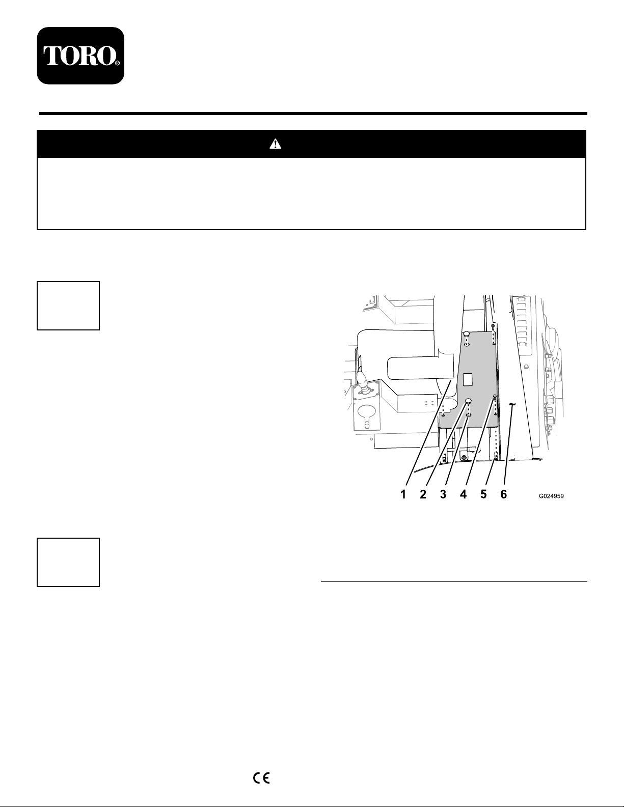
2
Note:Thebatterycoverislocatedbetweenthe
operatorseatandtherearROPSbulkhead.
Figure1
1.Operatorseat4.Flange-headbolts(5/16x
1inch)
2.Finger-pullcover5.Nutclip
3.Hole(batterycover)6.ROPSbulkhead
RemovingtheRight-Cowl
Panel
NoPartsRequired
DisconnectingtheBattery
1.RotatetheBATTERY-DISCONNECTswitchtotheOff
position;refertoOperator’ sManualforthemachine.
2.Removethe2nger-pullcoversfromtheholesinthe
batterycover(Figure1).
©2015—TheToro®Company
8111LyndaleAvenueSouth
Bloomington,MN55420
Registeratwww.T oro.com.
3.Removethe4ange-headbolts(5/16x1inch)that
securethebatterycovertotheROPSplatform(Figure
1).
4.Usingthengerpulls,liftthebatterycoverupto
removeitfromtheROPSplatform(Figure1).
5.Removethelock-washernut(3/8inch)securingthe
negative-batterycableandringterminaltothenegative
studofthebatteryandremovethecablesfromthe
battery(Figure2).
OriginalInstructions(EN)
PrintedintheUSA
AllRightsReserved
*3395-583*A
Page 2
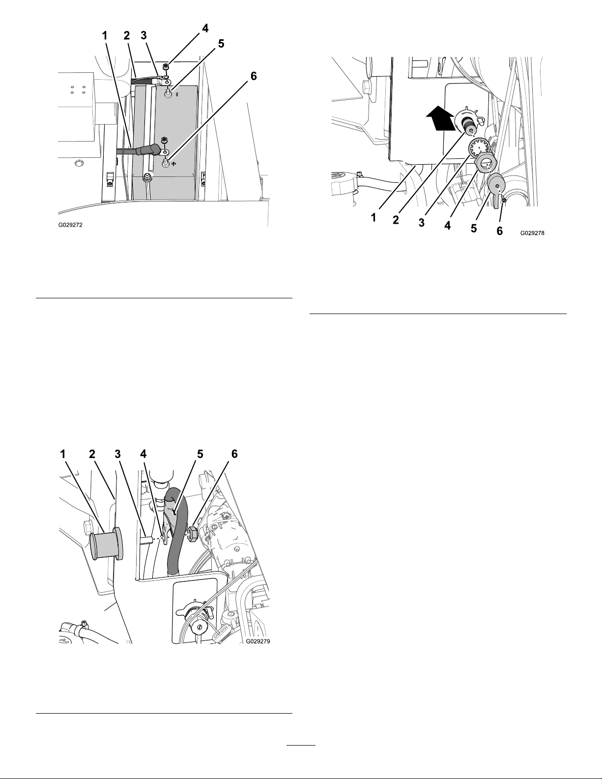
2.Atthebattery-disconnectswitch,removethescrewthat
securestheknobtotheshaftoftheswitch(Figure4).
Figure2
1.Positive-batterycable
2.Negative-batterycable
3.Ringterminal
4.Lock-washernut(3/8inch)
5.Negativestud(battery)
6.Positivestud(battery)
6.Movebacktheinsulatorbootandremovethe
lock-washernut(3/8inch)securingthepositive-battery
cabletothepositivestudofthebatteryandremovethe
cablefromthebattery(Figure2).
DisconnectingtheBattery-Disconnect
Switch
1.Attheinboardsideofthejumppost,movebackthe
insulatorboot,removethenut,andremovethecable
formthethreadedstud(Figure3).
Figure4
1.Right-cowlpanel4.Jamnut
2.Shaft(battery-disconnect
switch)
3.Lockwasher
5.Knob
6.Screw
3.Removethejamnutandlockwasherthatsecurethe
disconnectswitchtotheright-cowlpanel(Figure4).
4.Pushtheshaftofthebattery-disconnectswitch
rearwardtoseparatetheswitchfromthecowlpanel
(Figure4).
Figure3
1.Jumppost
2.Right-cowlpanel5.Insulatorboot
3.Threadedstud6.Locknut
4.Cableterminal
2
Page 3
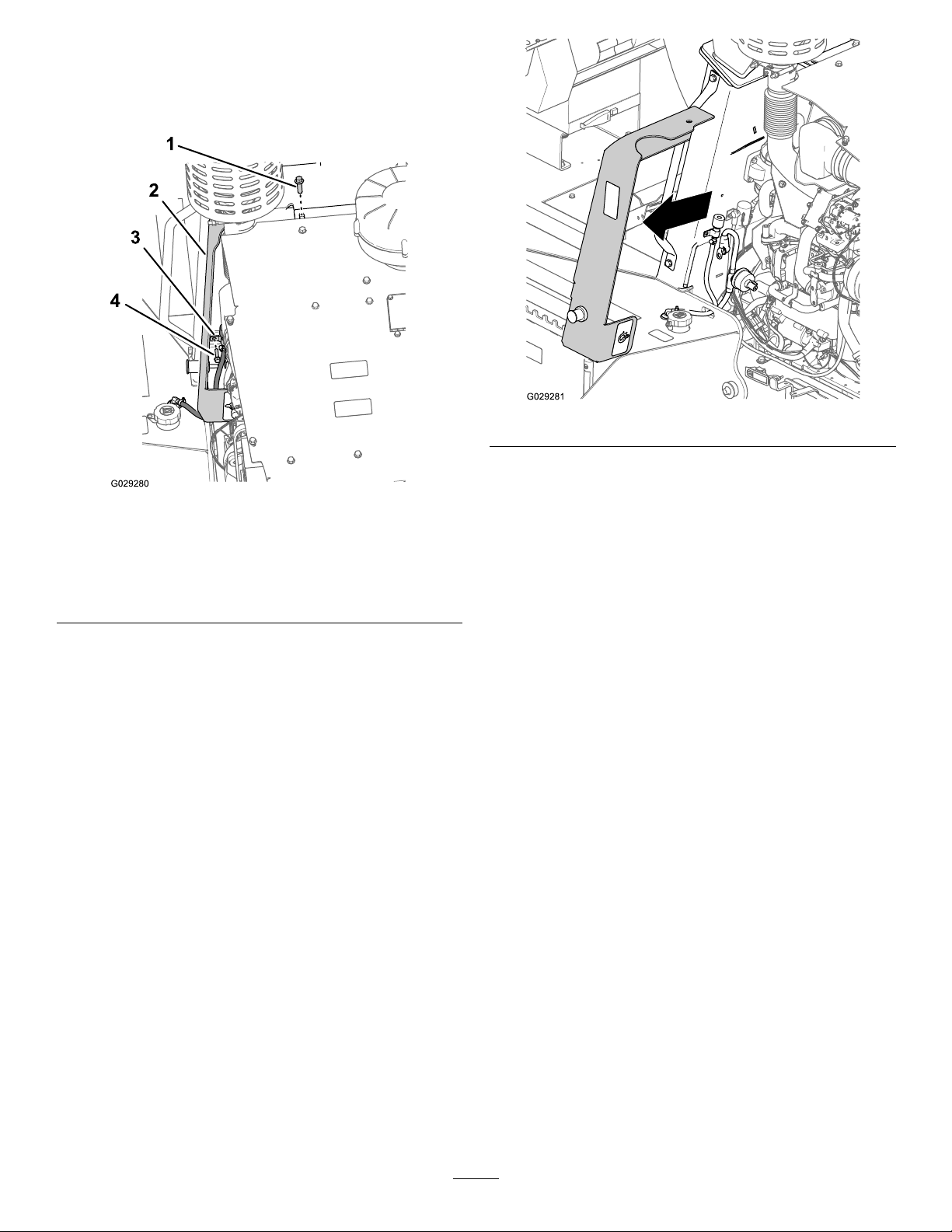
RemovingtheSide-CowlPanel
1.Removetheange-headbolt(12x40mm)thatsecures
theright-cowlpaneltotheROPS-mountingplate
(Figure5).
Figure6
Figure5
1.Flange-headbolt(12
x40mm)—upper
ROPS-mountingplate
2.Right-cowlpanel
3.Clamp(hydraulic-tank
breather)
4.Flange-headbolt(8x35
mm)—rewall
2.Removetheange-headbolt(8x35mm)thatsecures
theclampforthehydraulic-tankbreatherandthe
right-cowlpaneltotherewall(Figure5)
3.Removetheright-cowlpanelfromthemachine(Figure
6).
Note:Rotatethepanelasneededtocleartheexhaust
systemcomponents.
3
Page 4
3
RemovingtheExhaustSystem
NoPartsRequired
RemovingtheMuferandHeatShield
Note:Exhaustsystemweight:approximately39.5kg(88
lb).
1.Supporttheexhaustsystemwithliftingequipment
(Figure7).
Figure8
1.Flangenut4.Turbocharger-exhaust
pipe
2.Guillotineclamp5.Muferinletpipe
3.Bandclamp
3.Removethe4angelocknuts(8mm),4bolts(8x
120mm),andrearmountingplatethatsecurethe
exhaust-systemmounttothefrontrightROPStube
(Figure9).
Note:Retainthelocknuts,bolts,andmountingplate
forinstallationinAssemblingtheMufertothe
TurbochargerOutletPipe(page7).
Figure7
2.Removethebandclampandthelowerguillotineclamp
thatsecuresthemufertotheturbocharger-exhaust
pipe(Figure8).
Note:RetaintheclampsforinstallationinInstalling
theBellows-AlignmentJig(page5)andInstallingthe
GuillotineClampandtheBandClamp(page8).
Figure9
1.Bolts(8x120mm)
2.Rearmountingplate
3.ROPStube
4.Separatethemuferfromtheturbocharger-exhaust
pipeandremovethemuferfromthemachine(Figure
10).
Note:Donotremovetheheatshieldfromthemufer.
4.Exhaust-systemmount
5.Flangelocknuts(8mm)
4
Page 5

Figure10
5.Removetheangeclampthatsecurestheangeofthe
turbocharger-exhaustpipetotheoutletangeofthe
turbochargerandremovetheexhaustpipefromthe
machine(Figure11).
Note:Retaintheangeclampforinstallation
inInstallingtheTurbocharger-ExhaustPipeand
Pipe-AlignmentJig(page6);discardtheold
turbocharger-exhaustpipe.
4
Preparingthe
Turbocharger-ExhaustPipe
NoPartsRequired
PreparingtheMufer
1.Cleantheexteriorsurfaceoftheinletpipeforthe
mufer(Figure12).
Figure12
1.Flange
(turbocharger-exhaust
pipe)
2.Nut(angeclamp)
Figure11
1.Inletpipe(mufer)
2.Applyalightcoatofhigh-temperature,anti-galling
compoundtotheexteriorsurfaceofthemufer-inlet
pipe.
5
Installingthe
Turbocharger-ExhaustPipe
Partsneededforthisprocedure:
1Bellows-alignmentjig
1Turbocharger-exhaustpipe
3.Flange(turbocharger
outlet)
1Pipe-alignmentjig
InstallingtheBellows-AlignmentJig
1.Alignthebellows-alignmentjigtothenew
turbocharger-exhaustpipewiththeshorttabofthejig
belowthebellows(Figure13).
5
Page 6

Figure13
1.Guillotineclamp5.Leftleg(bellows-alignment
2.Flangenut
3.Bellows
(turbocharger-exhaust
pipe)
4.Insideradius
(turbocharger-exhaust
pipe)
jig)
6.Shorttab
(bellows-alignmentjig)
7.Rightleg
(bellows-alignmentjig)
2.Assembletheguillotineclampthatyouremovedinstep
2ofRemovingtheMuferandHeatShield(page4)to
thebellows-alignmentjig(Figure13).
3.Aligntheleftlegofthejigtotheoutsideradiusofthe
bendinthepipeandtherightlegtotheinsideradius
ofthebendasshowninFigure13.
4.Tightentheangenutsoftheguillotineclampto19
to25N-m(14to18ft-lb).
InstallingtheTurbocharger-Exhaust
PipeandPipe-AlignmentJig
Figure14
1.Turbocharger-exhaust
pipe(withthebellowjig
installed)
2.Flangeclamp
3.Turbocharger-outletange
2.Loosenthe2ange-headbolts(10x20mm)that
securetheupper-rearheatshieldtothestandoffsofthe
exhaustmanifold(AofFigure15).
Note:Youwillhavetoloosentheboltssothatyou
have5mm(3/16)ormoreclearancebetweenthehead
oftheboltandtheheatshield.
1.Assemblethenewturbocharger-exhaustpipetothe
outletangeoftheturbochargerwiththeangeclamp
thatyouremovedinstep5ofRemovingtheMufer
andHeatShield(page4)andtightentheangenutonly
enoughtokeepthepipealignedtotheturbocharger
(Figure14).
6
Page 7

6
InstallingtheMuferandHeat
Shield
Partsneededforthisprocedure:
3
Shim1.5mm(0.06inch)
1
Shim0.8mm(0.03inch)
AssemblingtheMufertothe
TurbochargerOutletPipe
1.Alignthebandclamparoundtheturbocharger-exhaust
pipe
2.Aligntheinletpipeofthemuferwiththe
turbocharger-exhaustpipe(Figure16).
Note:Ensurethatthealignmentpinsofthe
muferinletpipearealignedwiththeslotsinthe
turbocharger-exhaustpipeange.
Figure15
1.Turbocharger-exhaust
pipe
2.Flange-headbolts(10x
20mm)
3.Flangeclamp
4.Upper-rearheatshield
3.Assemblethepipe-alignmentjigontotheheatshield
andundertheange-headbolts(AofFigure15)and
tightentheboltsto17to21N-m(47to57ft-lb).
Note:Ensurethatthealignmentjigispushedinward
sothattheboltsarefullyseatedintheslotsofthejig.
4.Rotatetheexhaustpipesothatthesurfaceofthepipe
isushtothesmallangeofthepipe-alignmentjig
(BofFigure15).
Note:Thesmallangeofthepipe-alignmentjig
shouldalignbetweenthe2legsofthebellows-alignment
jig.Ifthebracketsarenotaligned,loosentheguillotine
clamp,positionthebellowsjig,andtightentheange
nutsoftheguillotineclampto19to25N-m(14to
18ft-lb).
5.Tightenthenutoftheangeclampsecurely.
5.Pipe-alignmentjig
6.Standoff(exhaust
manifold)
7.Smallange
(pipe-alignmentjig)
8.Pipesurface
(turbocharger-exhaust
pipe)
Figure16
1.Alignmentpin(muferinlet
pipe)
2.Bandclamp
3.Inserttheinletpipeintotheexhaustpipeintotheinlet
pipeisfullyseated(Figure16)
Note:Youshouldalignthepinatthemuferinletpipe
nearthebottomoftheslotintheturbocharger-exhaust
pipe.
Note:Donottwistthemuferwhileassemblingit
totheturbocharger-exhaustpipeoryoumaydamage
thebellows.
3.Slot
(turbocharger-exhaust
pipeange)
7
Page 8

4.Aligntheexhaust-systemmounttothefront,right
ROPStube(Figure17).
Figure17
InstallingtheGuillotineClampandthe
BandClamp
1.Removethe2ange-headboltsthatsecure
theguillotineclamp,bellows-alignmentjig,and
turbocharger-exhaustpipe,andremovethejig(Figure
18).
1.Rearmountingplate
2.Flange-headbolts(8x120
mm)
3.ROPStube7.Shim1.5mm(0.06inch)
4.Exhaust-systemmount
5.Flangelocknut(8mm)
6.Shim0.8mm(0.03inch)
5.Looselyassembletherearmountingplatetotheto
theexhaust-systemmount(Figure17)withthe4
ange-headbolts(8x120mm)and4angelocknuts
(8mm)thatyouremovedinstep3of3Removingthe
ExhaustSystem(page4).
6.Checkthegapbetweentheexhaust-systemmountand
theROPStube(Figure17).
Note:Ifneeded,addshimsbetweenthe
exhaust-systemmountandtheROPStubetomaintain
theaxialalignmentbetweenthemuferinletpipeand
theturbocharger-exhaustpipe.
7.Torquetheange-headboltsandangelocknutsto17
to21N-m(23to29ft-lb).
Figure18
1.Bellows-alignmentjig3.Bandclamp
2.Guillotineclamp
4.Turbocharger-exhaust
pipe
2.Assemblethebandclampjustbelowthealignmentpin
ofthemuferinletpipe(Figure16andFigure18).
3.Assembletheguillotineclampbetweenthealignment
pinandtheendoftheturbocharger-exhaustpipe
(Figure18).
4.Tightentheangenutsoftheguillotineclampand
tightentheboltandnutofthebandclamp.
5.Loosenthe2ange-headboltssecuringthe
pipe-alignmentjigtotheheatshieldandremovethe
alignmentjig(Figure19).
8
Page 9

Figure20
Figure19
1.Flange-headbolt2.Pipe-alignmentjig
6.Torquetheange-headboltsto34to42N-m(47to
57ft-lb).
7.Lookattheturbocharger-exhaustpipefromtheside
andconrmthatthebellowsisstraight.
Note:Ifthebellowsisnotalignedstraight,perform
thefollowing:
A.Loosentheange-headboltsandangelocknuts
thatsecuretheexhaust-systemmounttothe
ROPStube(Figure17).
B.Addorremoveshimstotheexhaust-system
mountasneededtoalignthebellows;refertostep
6inAssemblingtheMufertotheTurbocharger
OutletPipe(page7).
C.Torquetheange-headboltsandangelocknuts
fortheexhaust-systemmountto17to21N-m
(23to29ft-lb).
1.Flange-headbolts(6x16
mm)
2.Clipnut(6mm)
3.Flange-headbolts(6x30
mm)
4.Muferstrap
5.Heatshield
B.Loosentheange-headbolts(6x30mm)that
securethemuferstrapstotheexhaust-system
mount(Figure20).
C.Loosenthe2ange-headbolts(1/2x1inch)
andserratedangenuts(1/2inch)thatsecure
thelower-mufersupporttotheexhaust-system
mount(Figure21).
8.Lookattheturbocharger-exhaustpipefromthefront
andconrmthatthebellowsisstraight.
Note:Ifthebellowsisnotalignedstraight,perform
thefollowing:
A.Removethe6ange-headbolts(6x16mm)that
securetheheatshieldtotheexhaust-systemmount
andremovetheheatshield(Figure20).
9
Page 10

Figure21
1.Exhaust-systemmount
2.Flange-headbolts(1/2
x1inch)—lowermufer
support
D.Movethemuferleftorrighttoalignthebellows
(Figure21).
E.Tightenthe2ange-headbolts(1/2x1inch)
andserratedangenuts(1/2inch)thatsecure
thelower-mufersupporttotheexhaust-system
mountto91to113N-m(67to83ft-lb).
F.Tightentheange-headbolts(6x30mm)that
securethemuferstrapsto972to1198N-cm
(86to106in-lb).
G.Assembletheheatshieldtoexhaust-systemmount
withthe6ange-headbolts(6x16mm)and
torquetheboltsto972to1198N-cm(86to106
in-lb).
3.Lower-mufersupport
4.Serratedangenuts(1/2
inch)
7
InstallingtheRightSideCowl
Panel
NoPartsRequired
InstallingtheCowlPanel
1.Aligntheholesintherightside-cowlpanelwiththe
holesintheROPSplateandtherewall;refertoFigure
5inRemovingtheSide-CowlPanel(page3).
2.AssemblethecowlpaneltotheROPSplatewiththe
ange-headbolt(12x40mm)thatyouremovedin
step1ofRemovingtheSide-CowlPanel(page3).
3.Assembletheclampforthehydraulic-tankbreatherand
side-cowlpaneltotherewallwiththeange-headbolt
(8x35mm)thatyouremovedinstep2inRemoving
theSide-CowlPanel(page3).
Note:Ensurethatthebreatherisverticallyaligned.
4.Tightenthe12mmboltattheROPSplateto80to100
N-cm(59to73ft-lb)andtightenthe10mmboltatthe
rewallto44to57N-cm(34to42ft-lb).
AssemblingtheBattery-Disconnect
Switch
1.Assembletheelectricalcablethatyouremovedinstep
1ofDisconnectingtheBattery-DisconnectSwitch
(page2)ontothreadedstudofthejumppost(Figure
3)withthelocknut.
2.Aligntheelectricalcableatthestudofthejumppost
upward,tightenthelocknut,andaligntheinsulator
bootoverthenutandstud.
3.Assemblethebattery-disconnectswitchintothe
openingatthemountingangeoftherightside-cowl
panel(Figure4)withthelockwasherandjamnutthat
youremovedinstepof3andtightenthejamnut.
Note:Ensurethatthealignmentpinofthedisconnect
switchisalignedwiththeslotinthemountingange
ofthepanelandtheswitchisushtotheange.
4.Installtheknobontotheshaftofthedisconnect
switchwiththescrewthatyouremovedinstep2of
DisconnectingtheBattery-DisconnectSwitch(page2).
10
Page 11

ConnectingtheBattery
1.Assemblethepositive-batterycableintothepositive
studofthebattery(Figure2)withthelock-washernut
(3/8inch)thatyouremovedinstep6ofDisconnecting
theBattery(page1).
2.Torquethelock-washernutto(10to15ft-lb)andalign
theinsulatorbootoverthenutandstud.
3.Assemblethenegative-batterycableintothenegative
studofthebattery(Figure2)withthelock-washernut
(3/8inch)thatyouremovedinstep5ofDisconnecting
theBattery(page1).
4.Aligntheholesinthebatterycoverwiththeclipnuts
atthemountingangeforthecover(Figure1).
5.Securethebatterycovertothemachinewiththe4
ange-headbolts(5/16x1inch)thatyouremovedin
step3ofDisconnectingtheBattery(page1).
6.Installthenger-pullcoverintotheholesinthebattery
cover.
8
CompletingtheInstallationof
theKit
NoPartsRequired
Procedure
1.Rotatethebattery-disconnectswitchtotheOn
position;refertoOperator’ sManualforthemachine.
2.Starttheengineandcheckforexhaustleaksatthe
turbocharger-exhaustpipeandthemufer.
Note:Repairallleaksbeforeinstallingthesidepanel.
3.Installtheright-sidepanel;refertoOperator’sManual
forthemachine.
11
Page 12

 Loading...