

Page 1

StripingKit
2014or2015GrandStand
ModelNo.131-1470
Note:Determinetheleftandrightsidesofthemachinefromthenormaloperatingposition.
CALIFORNIA
Proposition65Warning
ThisproductcontainsachemicalorchemicalsknowntotheStateofCaliforniato
causecancer,birthdefects,orreproductiveharm.
®
Mowers
WARNING
Installation
FormNo.3385-772RevB
InstallationInstructions
LooseParts
Usethechartbelowtoverifythatallpartshavebeenshipped.
ProcedureDescription
1
2
3
4
Nopartsrequired
Mountingbracket2
Carriagebolt(3/8x1inch)
Flangenut(3/8inch)
Spring
Clevispin
Hairpincotter2
Nopartsrequired
1
PreparingtheMower
Qty.
–
2
2
2
2
–
5.Repairallbentordamagedareasandreplaceany
missingparts.
6.Raisetheplatformandverifythelatchissecurely
engagedtoholdtheplatformup.
Preparethemower.
Installthemountingbrackets.
Installtherollerassemblytostriper
bracketmounts.
Connectthechains.
Use
NoPartsRequired
Procedure
1.Parkthemachineonalevelsurface.
2.Engagetheparkingbrake.
3.Shutofftheengineandremovethekey .
4.Thoroughlycleanthemowerdeck.Removealldebris
toensurethatthekitwilltproperly .
©2017—TheToro®Company
8111LyndaleAvenueSouth
Bloomington,MN55420
Registeratwww.T oro.com.
OriginalInstructions(EN)
PrintedintheUSA
AllRightsReserved
*3385-772*B
Page 2

2
g026596
1 2
3
1
2
3
g026595
InstallingtheMounting
Brackets
Partsneededforthisprocedure:
2Mountingbracket
2
Carriagebolt(3/8x1inch)
2
Flangenut(3/8inch)
Procedure
1.Installthemountingbracketstotheoutsideholesfor
narrowbasemowers(48inchand52inchmowers)
andtheinsideholesforwidebasemowers(60inch
mowers)(Figure1).
g026595
Figure2
Shownwithnarrowbasemower
1.Flangenut(3/8inch)3.Carriagebolt(3/8x1inch)
2.Mountingbracket
3
InstallingtheRollerAssembly toStriperBracketMounts
Figure1
Shownwithnarrowbasemower
1.Mountingbracketinstalled
2.Usetheinsideholesfor
widebasemowers
2.Installthemountingbracketstothemachinewith2
carriagebolts(3/8x1inch)and2angenuts(3/8
inch)(Figure2).
3.Usetheoutsideholesfor
narrowbasemowers
Partsneededforthisprocedure:
2
Spring
2
Clevispin
2Hairpincotter
g026596
Procedure
1.Positionthespringsintothestripermountingbrackets
(Figure3).Ensurethattheshort-outsidengersonthe
springsareunderthemountingbrackets(Figure5).
2
Page 3
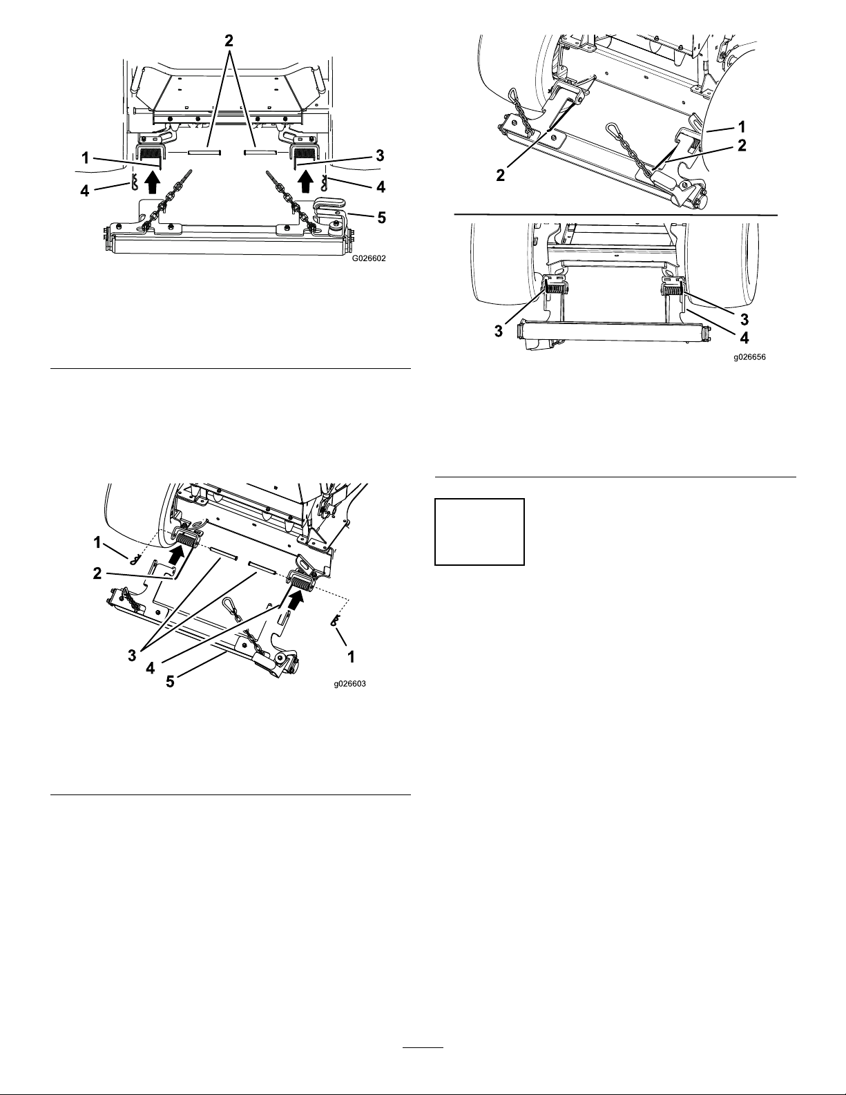
G026602
2
4
5
4
1
3
Figure3
g026603
1
2
3
4
1
5
g026656
1
2
2
3
4
3
g026602
1.Left-springlongnger
2.Clevispin
3.Right-springlongnger
4.Hairpin-cotter
5.Rollerassembly
2.Positiontherollerassemblyintothestripermounting
brackets(Figure4).
3.Inserttheclevispinthroughthestripermounting
bracket,rollermountandspringandsecureitwitha
hairpincotter(Figure4).
Figure4
1.Hairpincotter
2.Leftspringlongnger
3.Clevispin
4.Rightspringlongnger
5.Rollerassembly
g026656
Figure5
1.Topoftherollerassembly3.Short-springngerunder
2.Long-springngerontop
ofrollerassembly
mountingbracket
4.Bottomoftheroller
assembly
4
ConnectingtheChains
NoPartsRequired
Procedure
g026603
1.Holdtheoperatorplatformwhilereleasingthe
platformlatch.Lowertheplatformcompletelydown.
2.Withtheplatformdown,raisetherollerupandrotate
thelifthandleovertheplatform(Figure6).
4.Pulltheinsidespringngerupovertherollermount
(Figure5).
3
Page 4

Figure6
1.Leftlifthandle3.Rightlifthandle
2.Platformdown
4.Roller
3.Snapthechainendintotheholeinthelowerfront
sideplateoftheplatform.Repeatfortheopposite
side(Figure7).
Figure7
g011307
g010976
1.Holeinthelowerfrontside
plateoftheplatform
2.Snapring
4
Page 5

Operation
RaisingtheRoller
Withtheplatformdown,raisetherollerupandrotatethelift
handleovertheplatform(Figure8).
•Stiffgrasswherewheeltracksarelessvisiblewillusually
producepoorstriping.
•Coolseasongrasstypesfoundinnorthernareasare
usuallygoodforstriping.
•Warmseasongrasstypesfoundinsouthernareaswill
usuallyproducelesspronouncedstriping.
•Transitionzonegrassesfoundinthenarrowbeltregion
canproducegoodstripinginsomeareasandsome
portionsofthegrowingseason,whileproducingpoor
stripinginotherareasorportionsoftheseason.
•Somegrasstypesproducebetterstripingcontrastwhen
mowingshort.Othergrasstypesormoisturecontentof
thegrasscanprovidebettercontrastwhenmowingata
long/tallheightofcut.Experimentwithwhatworksbest
inyoursituation.
Stripingvisibilityisaffectedbythesun
position
Figure8
1.Leftlifthandle3.Rightlifthandle
2.Platformdown
4.Roller
RaisingthePlatform
1.Rotatethelifthandleofftheplatformtolowerthe
roller.
2.Raisetheplatform.Therollerwillalsoberaisedby
thechains.
3.Verifythatthelatchissecurelyengagedtoholdthe
platformandtherollerup.
RemovingtheRoller
1.Releasethechainendfromtheplatform.
2.Raisetheplatformup.
3.Releasethetensiononthespringsbyrotatingthelong
springngersoffoftherollermounts.
4.Removetheclevispinandhairpincotter.
5.Removetherollerfromthemachine.
6.Installthesprings,clevispinsandthehairpincotters
ontotherollerassemblyforlateruse.
OperatingTips
g011307
Thisishowthelightisreectedonthegrass.
•Mowingpatternswhichgenerallyruneast–westwillhave
agreatercontrastthannorth–southpatterns.
•Thestripingpatterncontrastislessvisiblearoundnoon,
andismorevisibleinmorningsandafternoons.
Stripingvisibilityisaffectedbyyour
position
Thegrasswhichisbenttowardsyouwillappeardarker,and
grasswhichisbentawayfromyouwillappearlighter.
•Mowingpatternswhichgenerallyrunalongaroadwill
havegreatercontrastwhenviewedapproachingorleaving
theproperty.Thecontrastofstripingwillbelessvisible
whenlookingacrossthemowingdirection.
•Ifthepropertyhasafocalpoint,oraviewinglocation,it
canbebenecialtomowinapatternthatisgenerallyto
andfromtheobservationpoint.
Lawnconditionaffectsstriping
visibility
•Largeatareasusuallyprovidebetterstripingcontrast
thanonslopesorareaswithalotoftrimmingandedging.
•Mowinginmorningdewcanproducegoodstriping
contrast.
•Doublecutmowing,andmowingasecondpassata
1/2inchlowerheightofcutcanproducegoodstriping
contrast.
Effectivestripingisinuencedbygrass
conditionandgrasstype
•Limpgrasswherewheeltracksareveryvisibleisusually
goodforstriping.
Mowingmodecanaffectstriping
contrast
•Sidedispersalofclippingscanhidestriping,reducingthe
contrasteffect.
5
Page 6

•Baggingcandisplayheavywheeltracks,reducingthe
effectofstriping.
•Mulchingwilloftendisplayexcellentcontrast,enhancing
theeffectofstriping.
Thelandscapecanpromoteorhinder
striping
•Themowingareasizehasaneffectonthenal
appearance.Largeareascanlookbetterwhenmowed
withalargemower.Smallareasmaynotlookrightwhen
cutwithalargemower.
•Largeareaswithoccasionaltreesorotherobstructions
willoftenlookbestwhenthemowingpatternappearsto
gothroughtheobstruction.Forexample,itcanlookbest
forapatterntomatchandcontinueonthefarsideofa
smallpond.Adifferentcrosscutpatternonthefarside
ofapondmaynotbevisible.
•Someareaslookbestwithlongstraightlinesofstriping
mowingpattern,alignedwithapropertyedge.Someareas
lookbestwithadiamondpattern,whereneitherstraight
lineisalignedwiththepropertyedge.Propertieswith
rollinghillsidesorpondscanlookbestwithaowing
curvesstripingpattern.Adistinctivefeaturelikeasmall
pondcanbehighlightedandenhancedbyaradialpattern
orbyaringpattern.
Somelawnsneedtobetrainedtoshow
adistinctivestripingcontrast
Drivingthemachinetodifferentcutting
areas
•Raisetherollerandthedeckanddrivealongaprevious
cutpathtotransportfromoneareaofthepropertyto
anothersection.
•Anicestripingpatterncanberuinedbydrivingacross
thepattern.
Followallgeneralmowingcommon
practices
•Itisusuallybesttorstmowtheperimetertoestablish
aboundary.
•Whensidedischarging,theclippingsshouldbedirected
awayfromwalks,drives,owerbeds,buildingsand
vehicles.Ifthedischargethrowsclippingsalongdistance,
mowadditionalpassestoavoidunwantedcleanupof
clippings.
•Avoidexcessivedrivingbackwards.Drivingbackand
forth,frequentforwardandreversemaneuversaround
anobstaclewillcompressthegrassanddisturbthe
professionalappearanceofanicejob.
•Avoidclosetrimmingwiththestripingkitinstalledto
reducedamagetolandscapingandtheroller.
•Followallsafemowingpracticesasdescribeinthe
Operator’sManual.Donotletthestripingpatterncause
youtomowintoahazardousmanner.
•Onanewpropertyduringweeks1and2,youmayneed
tofollowtheexactsamepatternanddirectioninthesame
wheeltracks.Thiswillbegintrainingthegrasstobendin
thedesireddirection.
•Onweek3useacross–grainstripingpattern.
•Onweeks4and5followwithrepeatingtheoriginal
pattern.Aftertheprimarystripingpatterngrainis
established,youmayalternatethepatterneachweek
toestablishacheckerboardoraplaidstyleofmowing
pattern.
•Donotmowintheexactsamepatterneveryweek.This
willcausecompactioninwheeltracks,andmayproduce
rutsordepressionsalongthewheeltracks.
Turningwhileusingthestripingkit
•Raisetherollerwhenturning.Stripingisgenerallynot
enhancedbyendturns.
•Raisingtherollerwillreduceconfusingthepatternatthe
endsofthepattern.
6
Page 7

Notes:
Page 8

 Loading...