

Page 1
BackllBladeKit
RT1160orRT1200Trencher
ModelNo.131-1286
ThisproductcontainsachemicalorchemicalsknowntotheStateofCaliforniato
causecancer,birthdefects,orreproductiveharm.
Safety
SafetyandInstructionalDecals
FormNo.3387-880RevB
InstallationInstructions
WARNING
CALIFORNIA
Proposition65Warning
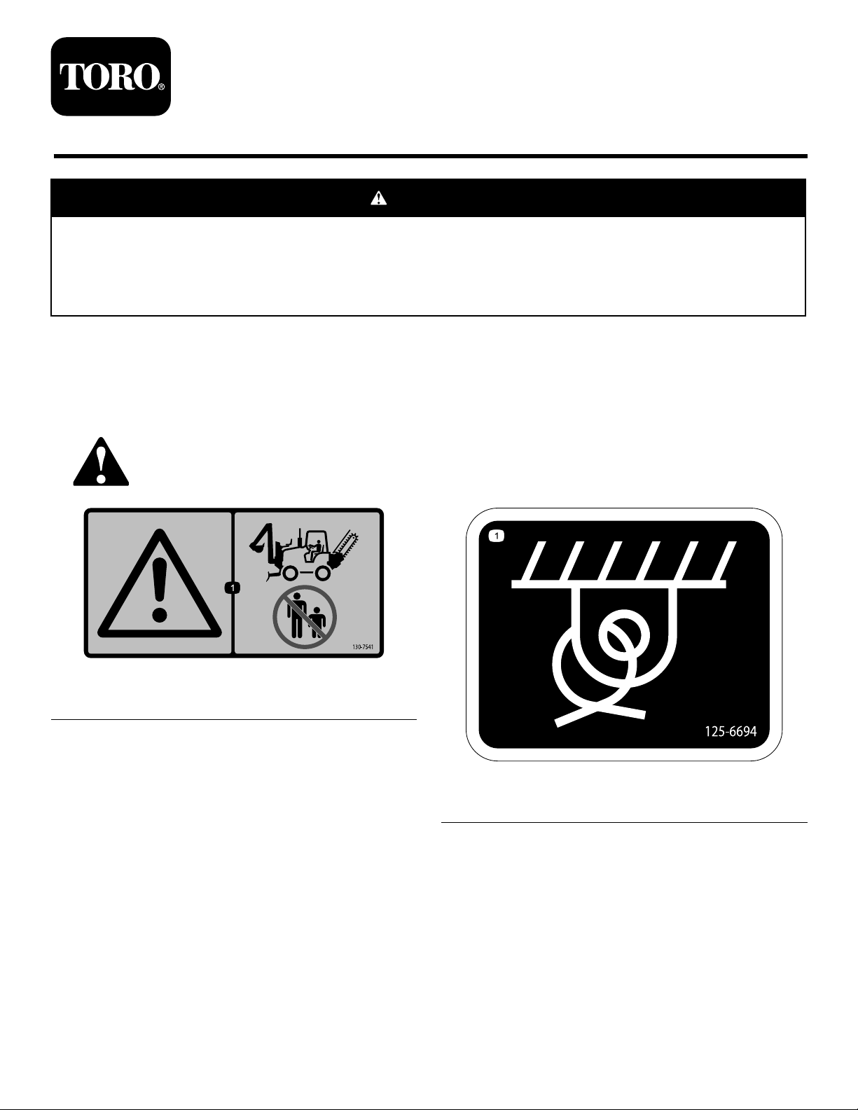
Safetydecalsandinstructionsareeasilyvisibletotheoperatorandarelocatednearanyareaofpotential
danger.Replaceanydecalthatisdamagedorlost.
130-7541
1.Warning—keepbystandersawayfromthemachine.
125-6694
1.Tie-downpoint
©2014—TheToro®Company
8111LyndaleAvenueSouth
Bloomington,MN55420
Registeratwww.T oro.com.
OriginalInstructions(EN)
PrintedintheUSA
AllRightsReserved
*3387-880*B
Page 2

LooseParts
Usethechartbelowtoverifythatallpartshavebeenshipped.
ProcedureDescription
1
2
3
4
5
6
7
Nopartsrequired
Pivotcylinder—retractedlength41.3cm
(16.25inch);roddiameter38.1mm(1.5
inch)
T-tting(3/8inch)
Cross-connecthose(1/4x20inch)
Mountingframe
Bolt(1x3-1/2inch)
Washer(1inch)
Locknut(1inch)
Bolt(1x2-1/2inch)
Pins(1-1/4x7-5/8inch)
Snaprings(1-1/8inch)
Washers(1x5/16inch)
Nopartsrequired
Pivotframe
Washers(1x5/8inch)
Pivotpin(1-1/2x15-1/2inch)
Snapring(1-3/8inch)
Pins(1-1/4x7-5/8inch)
Snaprings(1-1/8inch)
Lift-armassembly
Pin(1-1/2x5-1/4inch)
Snapring(1-3/8inch)
Liftcylinder—retractedlength51.4cm
(20.25inch);roddiameter38.1mm(1.5
inch)
Clevispin(1-1/4x4-7/16inch)
Hairpin2
Backllblade
Retainerplate2
Bolt(5/8x1-1/2inch)
Washer(5/8inch)
Retainedshim8
Tiltcylinder—retractedlength51.4cm
(20.25inch);roddiameter44.5mm
(1.75inch)
Clevispin(1-1/4x4-7/16inch)
Hairpin2
Qty.
12
Use
–
2
2
2
1
2
4
4
4
2
4
4
–
1
3
1
2
2
4
1
2
4
1
2
1
6
1
2
Preparetoinstallthebackllbladeto
themachine.
Installthesupportframe.
Assemblethepivotcylinderstothe
mountingframe.
Connectthepivotcylinderhoses.
Installthepivotframe.
Installthebladearms.
Installthebackllblade.
2
Page 3
ProcedureDescription
8
9
Liftcylinderextendhose(3/8x23
inches)
Liftcylinderretracthose(3/8x31-1/4
inch)
Tiltcylinderextendhose(3/8x49-1/4
inch)
Tiltcylinderretracthose(3/8x62-1/4
inch)
Clampblock(2-hose)
Bolt(3/8x1-3/4inch)
Washer(3/8inch)
Coverplate
Cabletie
Nopartsrequired
Qty.
Use
1
1
1
1
4
2
2
2
1
–
Installthehydraulichoses.
Bleedthehydraulicsystemforthe
backllblade.
10
Nopartsrequired
1
PreparingtoInstalltheBackll
BladetotheMachine
NoPartsRequired
PreparingtheMachine
1.Movethemachinetoalevelsurfaceandsettheparking
brake.
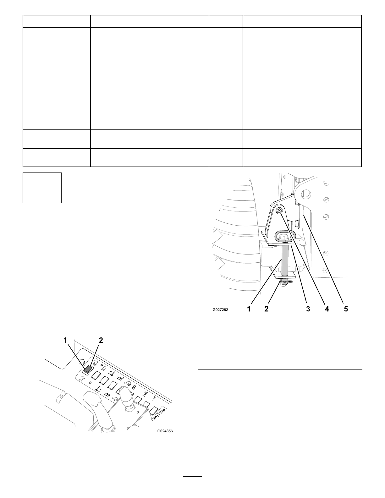
2.Ifyourmachinehasthetiltingframefeature,perform
thefollowingstepstolocktheaxleandframetogether:
A.Usethetiltswitchtoaligntheholeinthe
chassis-lockoutbracketwiththeholesinthe
axle-lockoutbracket(Figure1andFigure2).
–
1.Tilt-lockoutpin(stowed
positionshown)
2.Hairpin
3.Axle-lockoutbracket
(verticalholes)
Installthenosepanelandsidepanels.
Figure2
4.Hole—axle-lockout
bracket
5.Chassis-lockoutbracket
1.Tiltthemachineright
Figure1
2.Tiltthemachineleft
B.Removethehairpinfromthetilt-lockoutpin
(Figure2).
C.Removethetilt-lockoutpinfromthestowed
position(Figure2).
D.Fullyinsertthetilt-lockoutpinthroughthe
horizontalholesinthechassis-lockoutbracket
andaxle-lockoutbracket(Figure2).
E.Securethetilt-lockoutpintotheaxle-lockout
bracketwiththehairpin(Figure2).
3.Shutofftheengine,andallowthemachinetocool.
3
Page 4
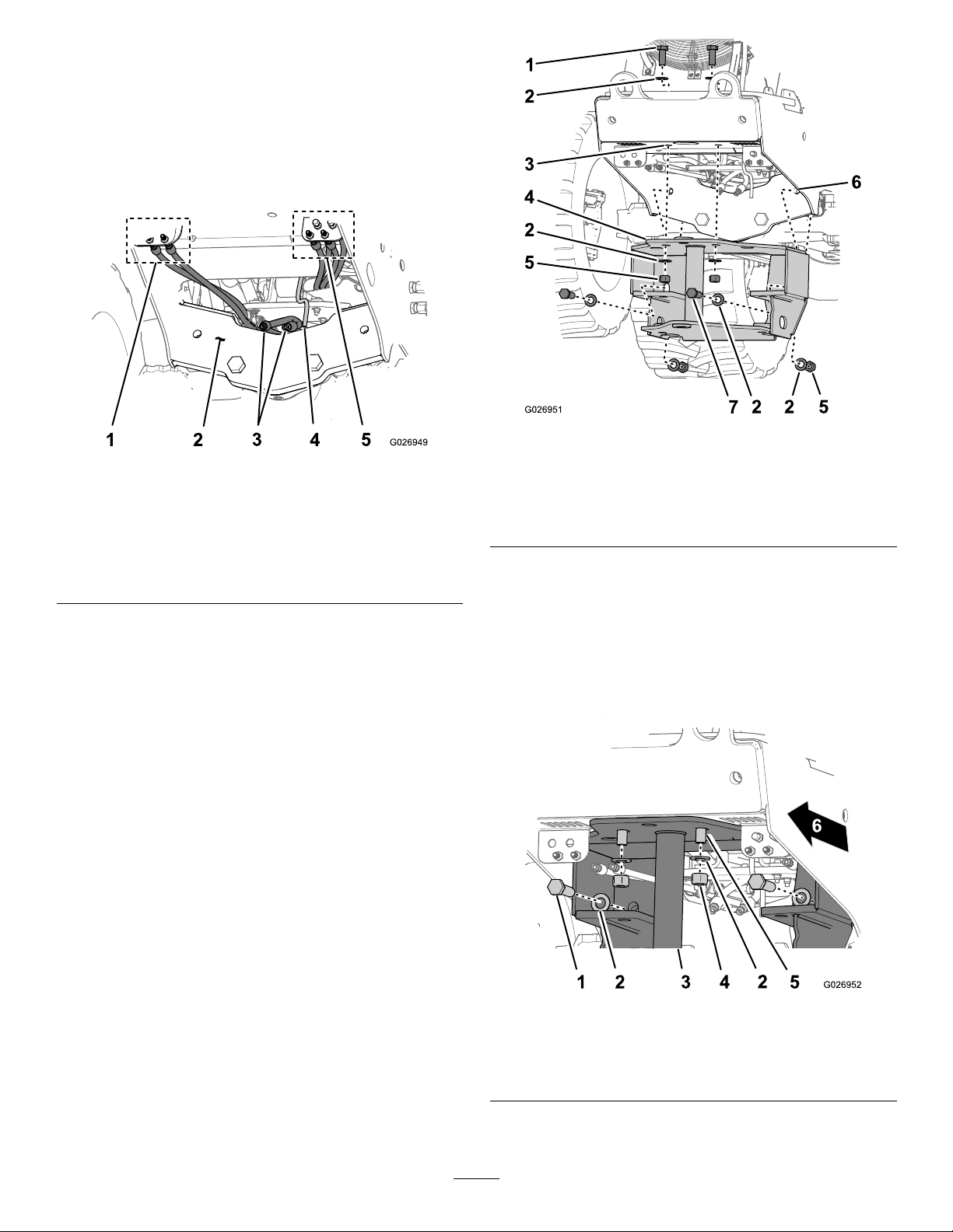
4.Atthefrontofthemachine,cleanthebottomofthe
g024963
1
2
3
4
frameplateandthefrontaxlesupportasshownin
Figure3.
Figure5
Figure3
1.Bulkheadttings4.Hosettings
2.Bottomframeplate5.Frontofthemachine
3.Frontaxlesupport
5.Cleanthebulkheadttingsandthehosettingsas
showninFigure3.
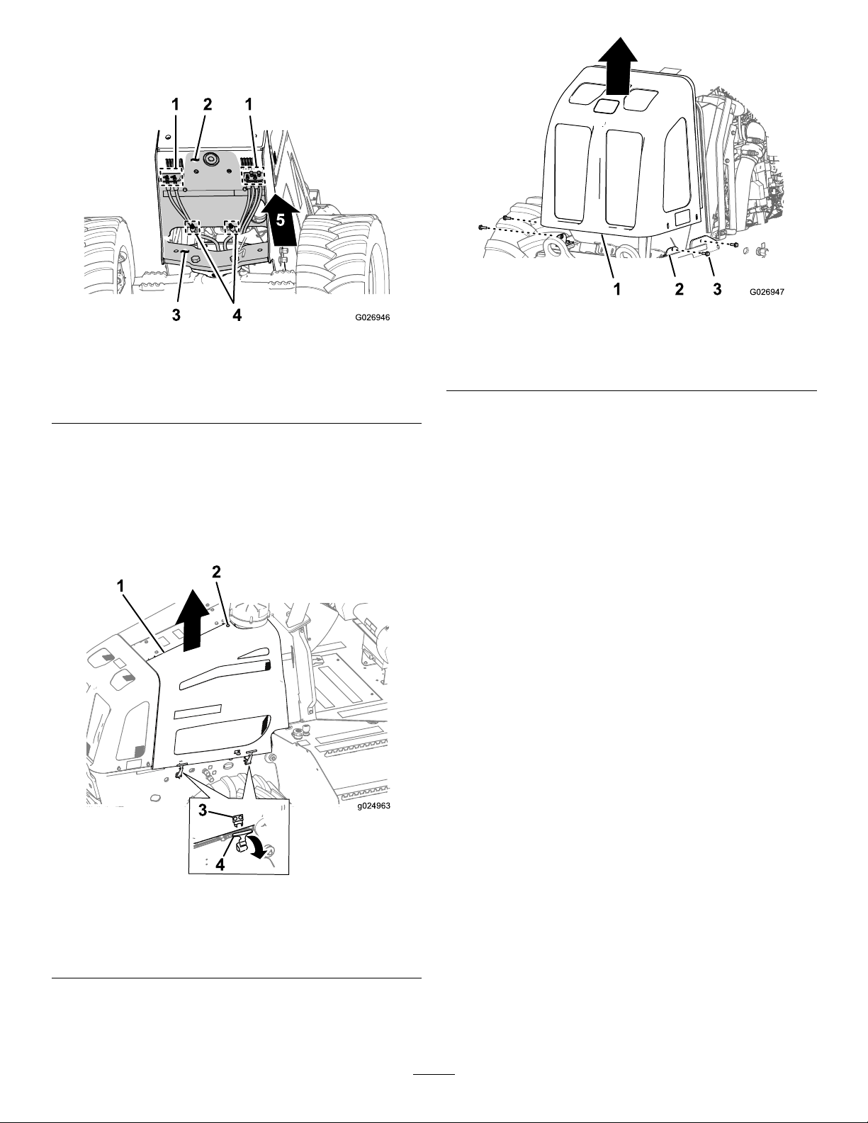
RemovingtheNosePanel
1.Removethesidepanels(Figure4),refertotheOperator’s
Manual.
1.Nosepanel3.Frame
2.Flanged-headbolt(10x
30mm)
3.Tiltthenosepanelforwardandthenliftitupoffthe
machine(Figure5).
Figure4
Rubberlatchhandlesshown
1.Sidepanel
2.Bolt4.Panellatch
3.Anchorbracket
2.Removethe4anged-headbolts(10x30mm)that
securethenosepaneltotheframeofthemachine
(Figure5).
4
Page 5
2
InstallingtheSupportFrame
Partsneededforthisprocedure:
Pivotcylinder—retractedlength41.3cm(16.25inch);
2
roddiameter38.1mm(1.5inch)
2
T-tting(3/8inch)
2
Cross-connecthose(1/4x20inch)
1
Mountingframe
2
Bolt(1x3-1/2inch)
4
Washer(1inch)
4
Locknut(1inch)
4
Bolt(1x2-1/2inch)
PreparingPivotCylinders
Pivotcylinderweight:14kg(30lb)
Note:Theretractedlengthofthepivotcylindersare41.3cm
(16.25inch)andtheroddiameteris38.1mm(1.5inch).
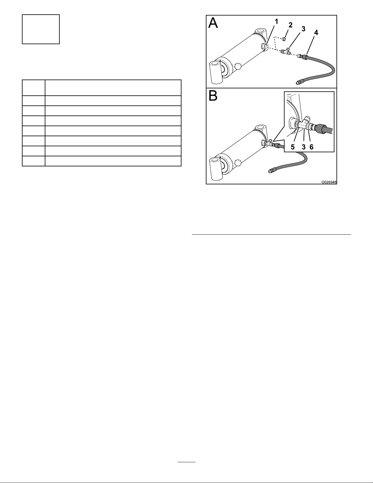
1.Removetheshippingplugfromtheextendportofa
pivotcylinder(Figure6).
Figure6
1.Extendport(pivotcylinder)4.Cross-connecthose(1/4x
20inch)
2.Shippingplug5.Swivelnut(T-tting)
3.T-tting(3/8inch)6.Swivelnut(hose)
2.InstallaT-tting(3/8inch)intotheextendport(Figure
6)andtightentheswivelnutofthettinghandtight.
3.Installacross-connecthose(1/4x20inch)ontothe
T-ttingsasshowninFigure6.
4.Tightentheswivelnutofthehosengertight.
5.Repeatsteps1through4fortheotherpivotcylinder,
T-tting,andhose(1/4x20inch).
5
Page 6
DisconnectingtheHydraulicHoses
fromtheBulkheadPanels
1.Atthefrontofthemachine,carefullyidentifyand
uniquelymarkthepositionofthehosesattheleftand
rightbulkheadpanels(Figure7).
Note:The2hosesthatarenotattachedtoeither
bulkheadpanelareforthepivotcylinders.
Figure8
Figure7
1.Hoses(rightbulkhead
panel)
2.Frontaxlesupport
3.Pivot-cylinderhoses
(rotateleftandrotateright)
4.Drainhose(coolant
reservoir)
5.Hoses(leftbulkhead
panel)
2.Removethehosesfromthettingsleftandright
bulkheadpanelsandcapthehoses(Figure7).
Note:Youwillconnectthehosestothebulkhead
panelsafteryouinstallthemountingframe.
InstallingtheMountingFrame
(MachineswithoutaMountingFrame
fortheBackllBlade)
Mountingframeweight:103kg(226lb)
1.Placethemountingframeontoliftingequipmentwith
a103kg(226lb)capacity.
2.Alignthe2horizontal25mm(1inch)holesinthe
mountingframewiththe2horizontalholesinthefront
axlesupport(Figure8).
1.Bolt(1x2-1/2inch)5.Locknut(1inch)
2.Washer(1inch)6.Hole(frontaxlesupport)
3.Hole(bottomframeplate)7.Bolt(1x3-1/2inch)
4.Mountingframe
3.Alignthe2vertical25mm(1inch)holesinthe
mountingframewiththe2verticalinthebottomframe
plateofthemachine(Figure8).
4.Assemble2bolts(1x3-1/2inch),2washers(1inch),
and2locknuts(1inch)throughthehorizontalholesin
themountingframeandthefrontaxlesupport(Figure
8,Figure9,andFigure10).
Figure9
1.Bolt(1x3-1/2inch)4.Washer(1inch)
2.Mountingframe5.Bolt(1x2-1/2inch)
3.Locknut(1inch)6.Frontofthemachine
6
Page 7
3
AssemblingthePivot CylinderstotheMounting Frame
Figure10
1.Bolt(1x3-1/2inch)4.Hole(frontaxlesupport)
2.Washer(1inch)5.Frontofthemachine
3.Locknut(1inch)
5.Assemble2bolts(1x2-1/2inch),2washers(1inch),
and2locknuts(1inch)throughtheverticalholesinthe
mountingframeandthebottomframeplate(Figure9
andFigure11).
6.Up
Figure11
Partsneededforthisprocedure:
2
Pins(1-1/4x7-5/8inch)
4
Snaprings(1-1/8inch)
4
Washers(1x5/16inch)
Procedure
Pivotcylinderweight:14kg(30lb)
Greasetype:lithium-basedgrease
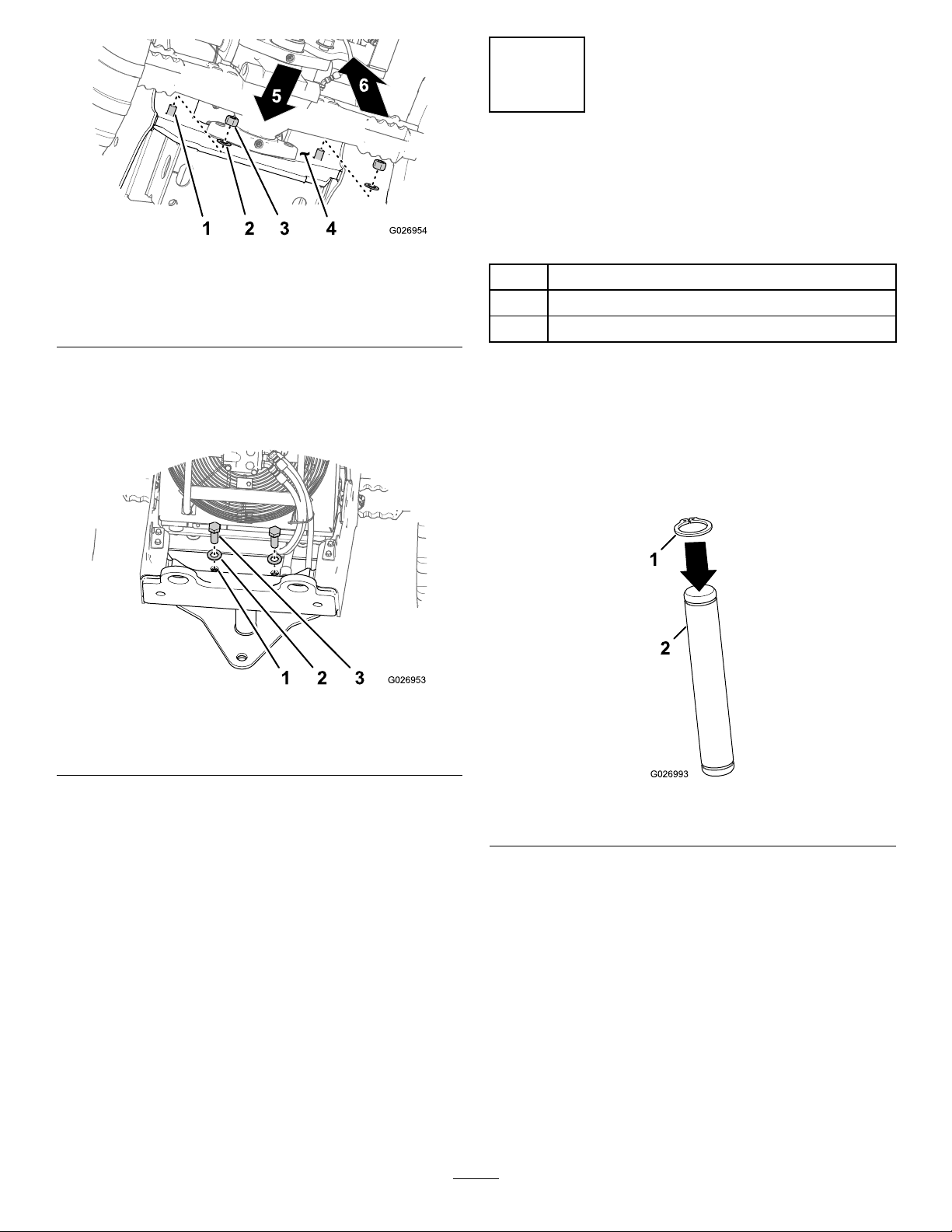
1.Install2snaprings(1-1/8inch)ontotheendofthe2
pins(1-1/4x7-5/8inch)asshowninFigure12.
1.Hole(bottomframeplate)3.Bolt(1x2-1/2inch)
2.Washer(1inch)
6.Torquetheboltsandnutsto977to1193N-m(720
to880ft-lb).
ConnectingtheHydraulicHosestothe
BulkheadPanels
1.Removethecapsandthehosesthatyouidentiedand
markedinstep1ofDisconnectingtheHydraulicHoses
fromtheBulkheadPanels(page6).
2.Connectthehosestothettingsintheleftandright
bulkheadpanels(Figure7).
3.Torquetheswivelnutsofthehosesto20.3to28.4
N-m(15–21ft-lb).
Figure12
1.Snapring(1-1/8inch)2.Pin(1-1/4x7-5/8inch)
2.Alignthemountingttingatthexedendofthepivot
cylinderontopofthebushinginthebottomplateof
themountingframe(Figure13).
Note:AligntheT-ttingthatyouinstalledinPreparing
PivotCylinders(page5)towardthecenterlineofthe
machine.
Note:Ensurethatthebottomofthemountingtting
ofthepivotcylinderisushtothebottomplateofthe
mountingframe.
7
Page 8
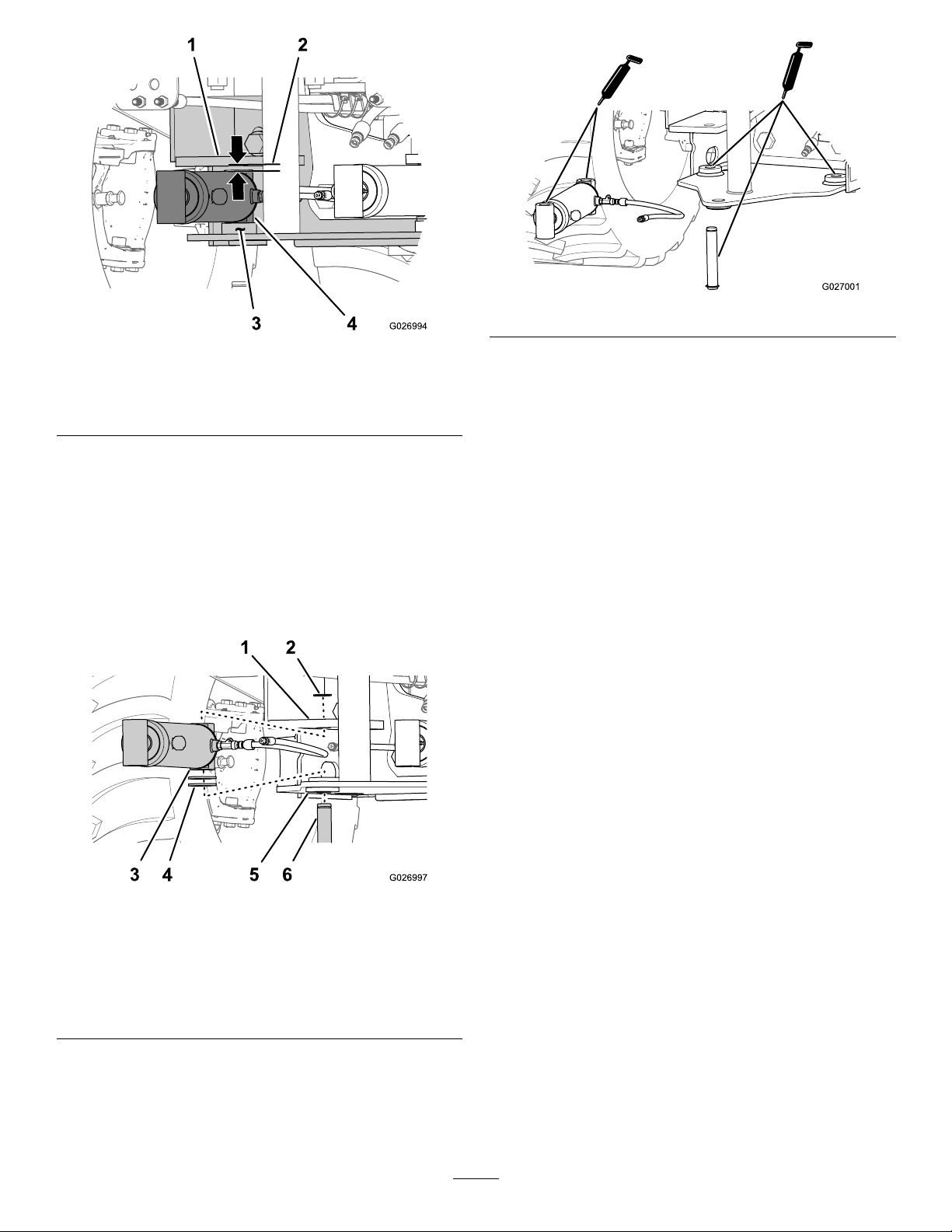
Figure13
1.Cylinderlug(mounting
frame)
2.Gap4.Pivotcylinder(xedend)
3.Bushing(bottomplateof
themountingframe)
3.Determinethenumberofwashers(1x5/16inch)
neededtoreducethegapbetweenthetopofthe
cylindermountingttingandthecylinderlugofthe
mountingframe(Figure13).
Note:Ateachcylinder,usethe(1x5/16inch)
washerstoreducethegapasrequired(0to2washers).
4.Removethecylinderandalignthewasher(s)thatyou
determinedinstep3ontopofthebushinginthe
supportframe(Figure14).
Figure15
6.Alignthemountingttingatthexedendofthe
pivotcylinderbetweenthebushing/washersandthe
mountinglug(Figure14).
Note:AligntheT-ttingtowardthecenterlineofthe
machine.
7.Aligntheholesinthemountinglug,mountingtting,
washer(s),andthebushing(Figure14).
8.Securethecylindertothesupportframewithapin
(1-1/4x7-5/8inch)thatyoupreparedinstep1and
installanapring(1-1/8inch)intotheothergroovein
thepin(Figure14).
9.Repeatsteps2through8fortheotherpivotcylinder.
Figure14
1.Cylinderlug(mounting
frame)
2.Snapring(1-1/8inch)5.Bushing(bottomplateof
3.Mounttting(pivot
cylinder)
4.Washers(1x5/16
inch—useasrequired)
themountingframe)
6.Pin(1-1/4x7-5/8inch)
5.Applyacoatofthespeciedgreasetothepin(1-1/4x
7-5/8inch),insidediameteroftheholeinthecylinder
lug,insidediameterofthemountingframebushing,
andinsidediameterofbothmountttingsofthepivot
cylinder(Figure15).
8
Page 9

4
ConnectingthePivotCylinder Hoses
NoPartsRequired
Procedure
1.Removetheplugfromthefreeendoftheleftandright
pivot-cylinderhoses.
2.Connecttheleftpivot-cylinderhosetotheT-ttingat
theleftpivotcylinder(Figure16)andtorquetheswivel
nutofthehoseto21to28N-m(15to21ft-lb).
Figure16
1.Pivot-cylinderhose(right)3.T-tting(3/8inch)
2.Pivotcylinders
4.Pivot-cylinderhose(left)
Figure17
1.Cross-connecthose
(T-tting—leftpivot
cylinder)
2.Retractport(rightpivot
cylinder)
7.Connectthefreeendofthehose(1/4x20inch)from
theT-ttingintherightpivotcylindertotheretract
portoftheleftpivotcylinder(Figure17)andtighten
thehosettingattheportto31to39N-m(23to29
ft-lb).
8.Tightentheswivelnutsofbothcross-connecthosesat
theT-ttingsto21to28N-m(15to21ft-lb).
9.Routethecoolantreservoirhosedownandthrough
theholeinthebottomplateofthemountingframe
(Figure18).
3.Retractport(leftpivot
cylinder)
4.Cross-connecthose
(T-tting—rightpivot
cylinder)
3.Connecttherightpivot-cylinderhosetotheT-tting
attherightpivotcylinder(Figure16)andtorquethe
swivelnutofthehoseto21to28N-m(15to21ft-lb).
4.RotatetheT-ttingsbackandupapproximately60°
(Figure16)andtorquetheswivelnutsfortheT-ttings
to32to39N-m(23to29ft-lb).
5.Removetheshippingplugsfromtheretractportsof
thepivotcylinders.
6.Connectthefreeendofthecross-connecthose(1/4
x20inch)fromtheT-ttingintheleftpivotcylinder
totheretractportoftherightpivotcylinder(Figure
17)andtightenthehosettingattheportto31to39
N-m(23to29ft-lb).
Figure18
1.Hole(mountingframe)2.Hose(coolantreservoir)
9
Page 10

5
InstallingthePivotFrame
Partsneededforthisprocedure:
1
Pivotframe
3
Washers(1x5/8inch)
1
Pivotpin(1-1/2x15-1/2inch)
2
Snapring(1-3/8inch)
2
Pins(1-1/4x7-5/8inch)
4
Snaprings(1-1/8inch)
Figure20
InstallingthePivotFrametothe
Machine
Pivotframeweight:65kg(142lb)
Greasetype:lithium-basedgrease
1.Install1snapring(1-3/8inch)intothegrooveinthe
pivotpin(1-1/2x15-1/2inch)asshowninFigure19.
1.Upperplate(mounting
frame)
2.Pivotpin(1-1/2x15-1/2
inch)
3.Pivotframe
4.Lowerplates(mounting
frame)
4.Alignthepivotholesinthepivotframeandmounting
frameandinsertthepivotpin(1-1/2x15-1/2inch)
thatyouassembledinstep1;refertoFigure20.
Note:Ensurethatthebottomofthepivotframeis
ushtothelowerplateofthemountingframe.
5.Determinethenumberofwashers(1x5/8inch)
neededtoreducethegapbetweentheupperplateof
themountingframeandthetopofthepivotframe
(Figure21).
Note:Usethe(1x5/8inch)washerstoreducethe
gapasrequired(0to3washers).
Figure19
1.Snapring(1-3/8inch)2.Pivotpin(1-1/2x15-1/2
inch)
2.Placethepivotframeontoliftingequipmentwitha65
kg(142lb)capacity.
3.Alignthepivotframebetweentheupperandlower
platesofthemountingframe(Figure20).
Figure21
1.Upperplate(mounting
frame)
2.Topofthepivotframe
3.Gap
6.Removethepivotpinfromthepivotframeand
mountingframe.
7.Separatethepivotframefromthemountingframe.
8.Applyacoatofthespeciedgreasetothepivotpin
andthepivotholesinthepivotframeandmounting
frame(Figure22andFigure23).
10
Page 11

Figure22
11.Insertthepivotpin(1-1/2x15-1/2inch)throughthe
mountingframe,washers,andpivotframebushings
andsecurethepinwithasnapring(1-3/8inch)as
showninFigure25andFigure26.
Figure25
Figure23
9.Alignthepivotframebetweentheupperandlower
platesofthemountingframe,andalignthepivotholes
inthepivotandmountingframes(Figure24).
Note:Ensurethatthebottomofthepivotframeis
ushtothelowerplateofthemountingframe.
1.Pivotpin
2.Bushing-upper(mounting
frame)
Figure26
1.Pivotframe3.Snapring(1-3/8inch)
2.Bushing-lowerplate
(mountingframe)
4.Pivotpin(1-1/2x15-1/2
inch)
Figure24
1.Pivotframe3.Upperplate(mounting
2.Washers(1x5/8
inch—useasrequired)
frame)
4.Lowerplate(mounting
frame)
10.Insertthewashersthatyoudeterminedinstep5
betweentheupperplateofthemountingframeandthe
topofthepivotframe(Figure24).
11
Page 12

AssemblingthePivotCylinderstothe
PivotFrame
Greasetype:lithium-basedgrease
1.Install2snaprings(1-1/8inch)ontotheendsofthe2
pins(1-1/4x7-5/8inch)asshowninFigure27.
Figure27
1.Snapring(1-1/4inch)2.Pin(1-1/4x7-5/8inch)
Figure29
5.Repeatsteps3and4fortheotherpivotframe
mountingpointandpivotcylinder.
2.Applyacoatofthespeciedgreasetothepins(1-1/4x
7-5/8inch)andtheinsidediameteroftheholesinthe
upperandlowerplatesforthepivotframe(Figure28).
Figure28
3.Alignthemountingholesinthepivotframewiththe
holesintherodttingforthecylinder(Figure28).
4.Insertapin(1-1/4x7-5/8inch)throughtheholesin
thepivotframeandrodttingsandsecurethepinwith
asnapring(1-1/8inch)asshowninFigure29.
12
Page 13

6
InstallingtheBladeArms
Partsneededforthisprocedure:
1
Lift-armassembly
2
Pin(1-1/2x5-1/4inch)
4
Snapring(1-3/8inch)
Liftcylinder—retractedlength51.4cm(20.25inch);
1
roddiameter38.1mm(1.5inch)
2
Clevispin(1-1/4x4-7/16inch)
2Hairpin
InstallingtheLiftArms
Liftarmweight:84kg(185lb)
1.Install2snaprings(1-3/8inch)ontotheendofthe2
pins(1-1/2x5-1/4inch)asshowningureFigure30.
Figure31
1.Fitting(lift-armassembly)3.Liftange(pivotframe)
2.Snaprings(1-3/8inch)4.Pins(1-1/2x5-1/4inch)
4.Aligntheholesinthettingswiththeholesinthe
anges(Figure31).
5.Insertapin(1-1/2x5-1/4inch)throughtheholesin
thettingandangesat1sideofthemachine(Figure
31).
6.Securethepinwithasnapring(1-3/8inch)asshown
inFigure31.
7.Repeatsteps5and6forthettingandangesonthe
othersideofthemachine.
Figure30
1.Snaprings(1-3/8inch)2.Pins(1-1/2x5-1/4inch)
2.Supportthelift-armassemblywithliftingequipment
witha84kg(185lb)capacity.
3.Alignthettingsattheendoftheliftarmswiththelift
angesofthepivotframe(Figure31).
8.Aligntheliftarmslevelandsupportthemwithjack
standswitha263kg(580lb)capacity.
13
Page 14

InstallingtheLiftCylinder
Liftcylinderweight12kg(25lb)
Note:Theretractedlengthoftheliftcylinderis51.4cm
(20.25inch)andtheroddiameteris38.1mm(1.5inch).
1.Aligntheholesintherodttingoftheliftcylinderwith
theholeinthemountinglugforthelift-armassembly
asshowninAofFigure32.
Note:Ensurethatthehydraulicportsofthecylinder
areup.
4.Securethecylindertothelugwithaclevispin(1-1/4x
4-7/16inch)andahairpin(Figure32).
Figure32
1.Rodtting(liftcylinder)5.Liftcylinder—retracted
2.Clevispin(1-1/4x4-7/16
inch)
3.Mountinglug(lift-arm
assembly)
4.Hairpin
length51.4cm(20.25
inch);roddiameter38.1
mm(1.5inch)
6.Hydraulicport
7.Cylinderlug(pivotframe)
8.Mountingtting(lift
cylinder—xedend)
2.Securetherodttingtothelugwithaclevispin(1-1/4
x4-7/16inch)andahairpin(Figure32).
3.Aligntheholesinthemountingttingatthexedend
oftheliftcylinderwiththecylinderlugofthepivot
frameasshowninBofFigure32.
Note:Manuallyextendorcollapsetheliftcylinderas
neededtoaligntheholes.
14
Page 15

7
InstallingtheBackllBlade
Partsneededforthisprocedure:
1
Backllblade
2Retainerplate
6
Bolt(5/8x1-1/2inch)
12
Washer(5/8inch)
8Retainedshim
Tiltcylinder—retractedlength51.4cm(20.25inch);
1
roddiameter44.5mm(1.75inch)
2
Clevispin(1-1/4x4-7/16inch)
2Hairpin
InstallingtheBackllBladeontothe
LiftArms
Backllbladeweight:1302kg(291lb)
1.Useliftingequipmenttoliftthebackllbladeand
alignittothemountingplateofthelift-armassembly
(Figure33).
Note:Alignthepivotttingofthebackllbladeinto
thepivotbushingofthemountingplateofthelift-arm
assembly.
Figure33
1.Backllblade5.Bolt(5/8x1-1/2inch)
2.Mountingplate(lift-arm
assembly)
3.Retainerplate
4.Washer(5/8inch)
6.Pivottting
7.Pivotbushing(mounting
plate)
8.Up
2.Usejackstandstosupporttheliftingarms.
DANGER
Ajackcansuddenlyfailresultingininjuryor
death.
•Neverrelyonahydraulicjacktosupport
weightofcomponents.
•Donotplaceyourbodyunderanyelevated
component(s).
3.Assemblethebackllbladetothemountingplatewith
2retainerplatesand4bolts(5/8x1-1/2inch),and4
washers(5/8inch)andtightentheboltsuntiltheyare
handtight(Figure34).
15
Page 16

Figure34
1.Threadedhole(backll
blade)
2.Retainerplate
3.Washer(5/8inch)
4.Bolt(5/8x1-1/2inch)
4.Checkthatthebackllbladehasasliptmovingthe
backllbladebyhand(Figure35).
1.Threadedplate(backll
blade)
2.Retainershim(useas
required)
3.Retainerplate
Figure36
4.Washer(5/8inch)
5.Bolt(5/8x1-1/2inch)
Note:Takesomeoftheliftingpressureoffthelifting
equipmenttoallowmovingthebackllblade.
B.Addaretainershimbetweenthethreadedplateof
thebackllbladeandtheretainerplate(Figure
36).
Note:Ateachretainerplate,usetheretainer
shimstoreducethegapasrequired(0to4shims).
C.Assembletheretainerplate,bolts,andwashers
untiltheyarehandtight(Figure36).
D.Checkthatthebackllbladehasasliptmoving
thebackllbladebyhand.Ifthebackllblade
doesnothaveaslipt,repeatstepAthoughD.
6.Removethebolts(5/8x1-1/2inch).
7.Applymedium-gradethread-lockingcompoundtothe
threadsofthe6bolts(5/8x1-1/2inch).
8.Assemblethebackllbladetothemountingplateat
eachsideofthemachinewiththe2retainerplates,6
bolts(5/8x1-1/2inch),6washers(5/8inch),andthe
shims(Figure36andFigure37)thatyoudetermined
instep5.
Figure35
5.Ifthebackllbladedoesnothaveaslipttothe
mountingplate,performthefollowingateachsideof
thebackllblade:
A.Removetheboltsandwashers(Figure36).
Figure37
1.Washers(5/8inch)3.Bolts(5/8x1-1/2inch)
2.Retainerplate
9.Torquetheboltsto136to163N-m(100to120ft-lb).
16
Page 17

InstallingtheTiltCylinder
Tiltcylinderweight:11.3kg(25lb)
Note:Theretractedlengthofthetiltcylinderis51.4cm
(20.25inch)andtheroddiameteris44.5mm(1.75inch).
1.Aligntheholeinthemountingttingatthexedend
oftheliftcylinder—retractedlength51.4cm(20.25
inch);roddiameter44.5mm1.75inch)withthehole
mountinglugatthelift-armassemblyasshowninA
ofFigure38.
8
InstallingtheHydraulicHoses
Partsneededforthisprocedure:
1
Liftcylinderextendhose(3/8x23inches)
1
Liftcylinderretracthose(3/8x31-1/4inch)
1
Tiltcylinderextendhose(3/8x49-1/4inch)
1
Tiltcylinderretracthose(3/8x62-1/4inch)
4
Clampblock(2-hose)
2
Bolt(3/8x1-3/4inch)
2
Washer(3/8inch)
2
Coverplate
1
Cabletie
InstallingtheLiftCylinderHoses
Figure38
1.Hairpin5.Hydraulicports
2.Mountinglug(lift-arm
assembly)
3.Mountingtting(lift
cylinder—xedend)
4.Clevispin(1-1/4x4-7/16
inch)
6.Rodtting(tiltcylinder)
7.Mountinglug(backll
blade)
2.Securethemountingttingoftheliftcylindertothe
mountinglugwithaclevispin(1-1/4x4-7/16inch)
andhairpin(Figure38).
3.Aligntheholesintherodttingofthetiltcylinder
withthecylinderlugofthebackllbladeasshownin
BofFigure38.
Note:Manuallyextendorcollapsetheliftcylinderas
neededtoaligntheholes.
4.Securetherodttingtothecylinderlugwithaclevis
pin(1-1/4x4-7/16inch)andahairpin(Figure38).
1.Removethecapsfromtheinboardandoutboard
bulkheadttingsoftheright-hydraulicpanel(Figure
39).
Figure39
1.Retractcircuit—liftcylinder
(right-hydraulicpanel)
2.Extendcircuit—liftcylinder
(right-hydraulicpanel)
3.Extendcircuit—tilt
cylinder(left-hydraulic
panel—lowerrow)
4.Retractcircuit—tilt
cylinder(left-hydraulic
panel—lowerrow)
2.Removetheshippingcapsfromtheextendandretract
portsoftheliftcylinder.
3.Connecttheliftcylinderextendhose(3/8x23inches)
betweenthebulkheadttingfortheliftcylinderextend
circuitattheright-hydraulicpanelandtheextendport
oftheliftcylinder(Figure40).
5.Liftthebackllbladeslightlywiththeliftingequipment,
removethejackstands,lowerthebackllblade,and
removetheliftingequipment.
17
Page 18

Figure40
InstallingtheTiltCylinderHoses
1.Removethecapsfromthetiltcylinderextendand
retractportsoftheleft-hydraulicpanel(Figure39).
2.Removetheshippingcapsfromtheextendandretract
portsofthetiltcylinder.
3.Connectthetiltcylinderextendhose(3/8x49-1/4
inch)betweenthebulkheadttingforthetiltcylinder
extendcircuitattheleft-hydraulicpanel.andtheextend
portofthetiltcylinder(Figure42).
1.Bulkheadtting—lift
cylinderextendcircuit
(right-hydraulicpanel)
2.Liftcylinderextendhose
(3/8x23inches)
3.Extendport(liftcylinder)
4.Connecttheliftcylinderretracthose(3/8x31-1/4
inch)betweenthebulkheadttingfortheliftcylinder
retractcircuitattheright-hydraulicpanel.andthe
retractportoftheliftcylinder(Figure41).
Figure41
Figure42
1.Bulkheadtting—tilt
cylinderextend
circuit(left-hydraulic
panel—lowerrow)
2.Tiltcylinderextendhose
(3/8x49-1/4inch)
3.Extendport(tiltcylinder)
4.Connectthetiltcylinderretracthose(3/8x62-1/4
inch)betweenthebulkheadttingforthetiltcylinder
retractcircuitattheleft-hydraulicpanel.andtheretract
portofthetiltcylinder(Figure43)
Note:Ensurethatthetiltcylinderretracthoseis
routedoutboardofthetiltcylinderextendhose.
1.Bulkheadtting—lift
cylinderretractcircuit
(right-hydraulicpanel)
2.Liftcylinderretracthose
(3/8x31-1/4inch)
3.Cabletie
4.Retractport(liftcylinder)
5.Attheliftcylinderports,torquethehosettingsto31
to39N-m(23to29ft-lb).
6.Atthehydraulicpanel,torquetheswivelnutsforthe
hosesto21to28N-m(15to21ft-lb).
7.Securetheretracthosetotheliftcylinderwithacable
tie(Figure41).
18
1.Retractport(tiltcylinder)
2.Bulkheadtting—tilt
cylinderretract
circuit(left-hydraulic
panel—lowerrow)
Figure43
3.Tiltcylinderretracthose
(3/8x62-1/4inch)
Page 19

5.Atthetiltcylinderports,torquethehosettingsto31
to39N-m(23to29ft-lb).
6.Atthehydraulicpanel,torquetheswivelnutsforthe
hosesto21to28N-m(15to21ft-lb).
7.Applymedium-gradethread-lockingcompoundtothe
threadsofthe2bolts(3/8x1-3/4inch).
8.Attheweldnutontheleftliftarm,securethehoses
with2clampblocks,bolt(3/8x1-3/4inch),washer
(3/8inch),andcoverplate(Figure44).
9
BleedingtheHydraulicSystem
fortheBackllBlade
NoPartsRequired
PreparingtheMachine
UseT oroPremiumAll-seasonHydraulicFluid(available
in5-gallonpailsor55-gallondrums.SeethePartsCatalogor
anAuthorizedToroServiceDealerforpartnumbers).
IfTorohydraulicuidisnotavailable,youmayusean
equivalenthydraulicuid,providedthatitmeetsallthe
followingmaterialpropertiesandindustryspecications.Do
notuseasynthetichydraulicuid.Consultwithyour
lubricantdistributortoidentifyasatisfactoryproduct.
HighViscosityIndex/LowPourPoint
Anti-wearHydraulicFluid,ISOVG46
MaterialProperties:
St@40°C(104°F):44to48 Viscosity,ASTMD445
St@100°C(212°F):7.9to8.5
ViscosityIndexASTM
D2270
PourPoint,ASTMD97-37°C(-34°F)to-45°C(-49°F)
FZG,Failstage
Watercontent(newuid)500ppm(maximum)
IndustrySpecications:VickersI-286-S(QualityLevel),
VickersM-2950-S(Quality
Level),DenisonHF-0
140to160
11orbetter
Figure44
1.Clampblocks(2-hose)4.Bolt(3/8x1-3/4inch)
2.Coverplate
3.Washer(3/8inch)
9.Attheweldnutonthetopplateofthepivotframe,
securethehoseswith2clampblocks,bolt(3/8x1-3/4
inch),washer(3/8inch),andcoverplate(Figure44)
Note:Ensurethatthereisslackinthehosesbetween
theclampblocksattheliftarmandthepivotframe
(Figure44).
10.Torquetheboltsto37to45N-m(27to33ft-lb).
5.Tiltcylinderextendhose
6.Tiltcylinderretracthose
1.Checkthehydraulic-uidlevelinthesightglasslocated
atthesideofthehydraulicreservoir(Figure45).
Note:Thehydraulic-uidlevelshouldbebetweenthe
bottomandmidpointofthesightglass.
19
Page 20

2.Slowlyraiseandlowerthebackllbladebymoving
therightjoystickrearwardandforward(Figure47and
Figure48).
Note:Movethebladeupanddownuntiltheblade
raisesandlowerssmoothly
Important:Donotpressthetriggertooatthe
blade.
Figure47
Figure45
1.Fillcap(off)3.Hydraulicuidlevelatthe
midpointofthesightglass
2.Hydraulicuid
2.Ifthehydraulic-uidlevelisnotvisibleinthesight
glass,removethellcap(Figure45),addthespecied
hydraulicuiduntiltheuidlevelisatthemidpointof
thesightglass,andinstallthellcap.
3.Ensurethattheparkingbrakeisset.
4.Startthemachine;refertotheOperator’sManual.
BleedingtheBackllBladeHydraulic
System
1.Switchthemachinetothebackllbladefunctionby
pressingbutton5onthecommandcenteruntilthe
iconforthebackllbladeappears(Figure46).
1.Lowertheblade(joystick)5.Turnthebladeleft
2.Raisetheblade(joystick)
3.Tiltthebladeleft(joystick)7.Floattheblade(trigger)
4.Tiltthebladeright
(joystick)
Figure48
1.Lowerthebackllblade2.Raisethebackllblade
(left-thumbcontrol)
6.Turnthebladeright
(right-thumbcontrol)
3.Movethebladeupsothattheliftarmsareparallelto
theground.
4.Pivotthebladefullyrightbypressingtheright-thumb
control(Figure47andFigure49).
Figure46
1.Button5—backllblade/vibratoryplowselection
(backll-bladeiconshown)
20
Page 21

Figure49
6.Slowlytiltthebackllbladedownattheleftsideand
thendownattherightsidebytwistingtherightjoystick
clockwiseandcounterclockwise(Figure47andFigure
51).
Note:Tiltthebladeleftsidedownandrightside
downuntilthebladetiltssmoothly .
1.Pivot—left
5.Ifthebackllbladepivotstotheleft,leavethebackll
bladeturnedleftandperformthefollowing:
Note:Ifthebackllbladeswingsright,skiptostep6.
A.Lowerthebackllbladetothegroundbymoving
therightjoystickforward(Figure47).
B.Shutofftheengine.
C.Placearagoverthepivot-cylinderhosesand
loosentheswivelnuts(Figure50).
2.Pivot—right
Figure51
1.Down—left
7.Centerthebackllblade,lowerittotheground,and
shutoffthemachine.
8.Checkthehydraulicttings,hoses,andcylindersfor
leaks.
Note:Repairallhydraulicleaksbeforeyouoperate
themachine.
9.Checkthehydraulic-uidlevel;refertosteps1and2
inPreparingtheMachine(page19).
2.Down—right
Figure50
1.Pivot-cylinderhose(move
totheT-ttingfortheright
pivotcylinder)
2.Pivotcylinders
D.Switchthepositionofthe2hosestotheT-tting
oftheoppositepivotcylinders(Figure50).
E.Torquetheswivelnutsforthe2pivotcylinder
hosesto21to28N-m(15to21ft-lb).
F.Startthemachineandfullyraisethebackllblade.
Important:Donotpressthetriggertooat
theblade.
G.Slowlyturnthebackllbladeleftandrightby
pressingtheleftandright-thumbcontrols(Figure
47).
Note:Movethebackllbladeleftandrightuntil
thebladepivotssmoothly.
3.T-tting(3/8inch)
4.Pivot-cylinderhose(move
totheT-ttingfortheright
pivotcylinder)
10
InstallingtheNosePanel
NoPartsRequired
Procedure
1.Applymedium-duty,threadlockingcompoundtothe
threadsofthe4anged-headbolts(10x30mm)that
youremovedinstep2ofRemovingtheNosePanel
(page4).
2.Alignthe4holesinthenosepanewiththe4weldnuts
intheframeofthemachine(Figure5).
3.Installthenosepaneltothemachinewiththe4
anged-headbolts(Figure5).
4.Torquetheboltsto47to57N-m(34to42ft-lb).
5.Installthesidepanels(Figure4);refertotheOperator’ s
Manual.
21
Page 22

Notes:
22
Page 23

Notes:
23
Page 24

 Loading...