

Page 1

HydraulicMotorKit
TRX-16orTRX-20Trencher
ModelNo.131-0667
ThisproductcontainsachemicalorchemicalsknowntotheStateofCaliforniato
causecancer,birthdefects,orreproductiveharm.
LooseParts
Usethechartbelowtoverifythatallpartshavebeenshipped.
FormNo.3411-315RevA
InstallationInstructions
WARNING
CALIFORNIA
Proposition65Warning
ProcedureDescription
1
2
3
4
5
Nopartsrequired
Cabletie
Hydraulicmotor1
Spacerplate
Coupler
Socket-headbolt(1/2x1-3/4inches)
Lockwasher(3/4inch)
Thread-lockingcompound1
Nopartsrequired
Nopartsrequired
Qty.
–
1Removethehydraulicmotor.
1
1
2
2
–
–
Preparethemachine.
Installthehydraulicmotor.
Connectthehydraulichoses.
Checkforleaksandservicethe
hydraulicuid.
Use
©2016—TheT oro®Company
8111LyndaleAvenueSouth
Bloomington,MN55420
Registeratwww.T oro.com.
OriginalInstructions(EN)
PrintedintheUSA
AllRightsReserved
*3411-315*A
Page 2
1
2
PreparingtheMachine
NoPartsRequired
Procedure
1.Movethemachinetoalevelsurfaceandlowerthe
boom.
2.Engagetheparkingbrake,shutofftheengine,and
removethekeyfromtheignitionswitch.
3.Allowthehydraulicsystemtocool.
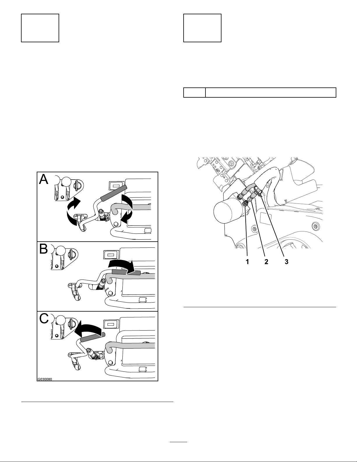
4.Rotatethetrenchercontrolclockwise(AofFigure1).
5.Movethetrencher-controlleverfullytotheforward
position(BofFigure1)andbackwardposition(Cof
Figure1)4or5times.
RemovingtheHydraulicMotor
fortheTrencherDrive
Partsneededforthisprocedure:
1
Cabletie
Procedure
1.Alignadrainpanunderthehydraulicmotorforthe
trencherdrive.
2.Wipecleanthehydraulichosesandttingsatthe
hydraulicmotorforthetrencherdrive(Figure2).
Figure1
Note:Movingthetrencher-controlleverbleeds
hydraulicpressurefromthehosesforthetrencher
motor.
g191412
Figure2
1.Straighthydraulictting
(rear)
2.Hose(rear)
3.Securethecabletietotherearmosthydraulichoseat
thehydraulicmotorforthetrencherdrive(Figure2).
4.Removethe2hydraulichosesfromthestraight
hydraulicttinginthehydraulicmotor(Figure3).
g030080
3.Cabletie
2
Page 3
3
InstallingtheHydraulicMotor
Partsneededforthisprocedure:
1Hydraulicmotor
1
Spacerplate
1
Coupler
2
Socket-headbolt(1/2x1-3/4inches)
2
Lockwasher(3/4inch)
1Thread-lockingcompound
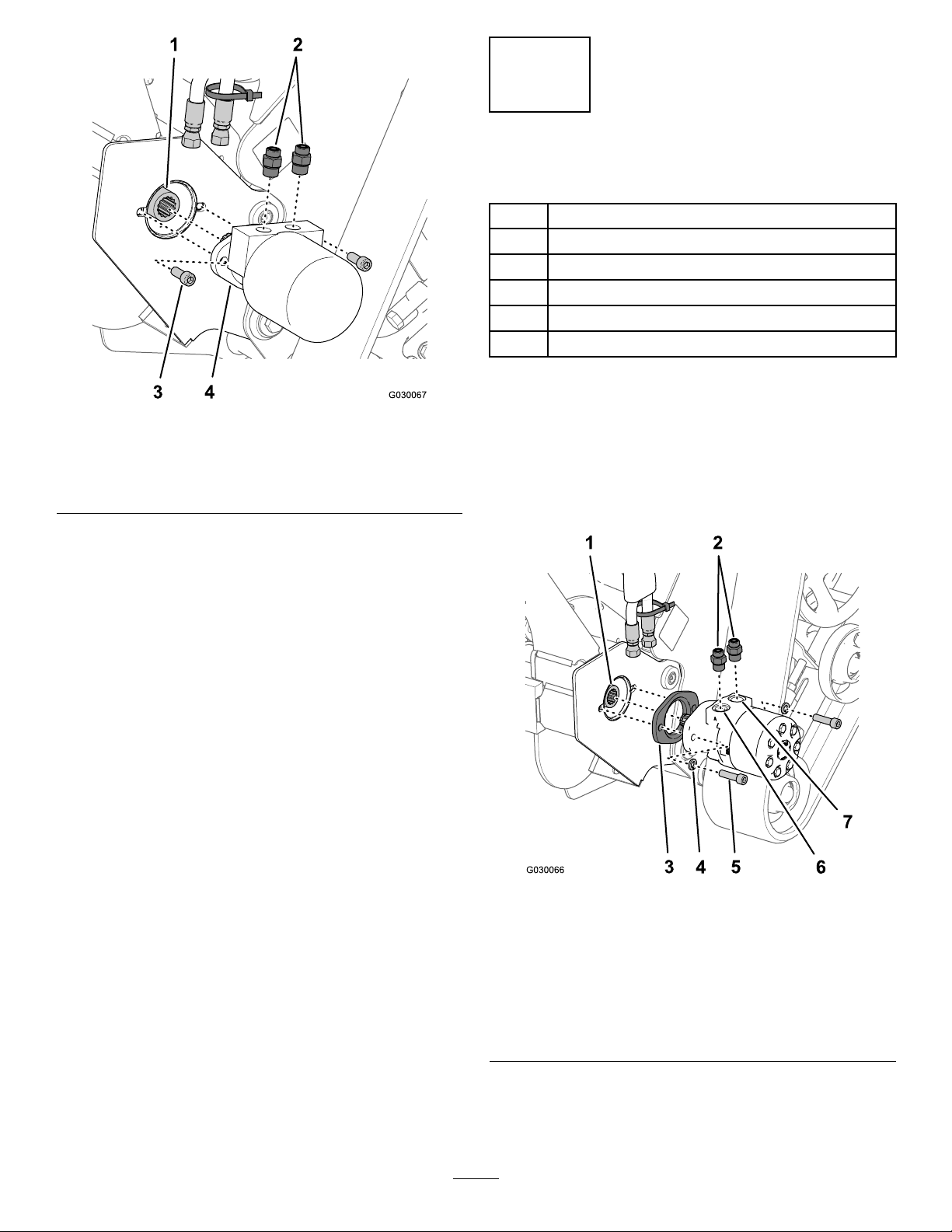
Figure3
1.Coupler(trencher-drive
shaft)
2.Straighthydraulictting4.Hydraulicmotor(old)
3.Socket-headbolts(1/2x
1-1/4inches)
5.Removethe2socket-headbolts(1/2x1-1/4inches)
thatsecurethehydraulicmotorforthetrencherdrive
totheheadofthetrencher,andremovethehydraulic
motor(Figure3).
Note:Discardthe2socket-headbolts(1/2x1-1/4
inches).
6.Drainthehydraulicuidfromthemotorintothedrain
pan.
7.Removethe2straighthydraulicttingsfromtheold
hydraulicmotor(Figure3).
Note:Discardtheoldhydraulicmotor.
8.Removethecouplerfromthetrencher-driveshaft
(Figure3).
Note:Discardtheoldcoupler.
g030067
Procedure
1.Slidethenewcouplerontothetrencher-driveshaft
(Figure4).
2.Assemblethe2straighthydraulicttingsintothenew
hydraulicmotorforthetrencherdrive(Figure4)and
torquethettingsto135to164N∙m(99to121ft-lb).
Figure4
1.Coupler(trencher-drive
shaft)
2.Straighthydraulictting6.PortA(hydraulic
3.Spacerplate7.PortB(hydraulic
4.Lockwashers(3/4inch)
5.Socket-headbolts(1/2x
1-3/4inches)
motor—new)
motor—new)
3.Applyacoatofthread-lockingcompoundtothe
threadsofthe2newsocket-headbolts(1/2x1-3/4
inches).
3
g030066
Page 4

4.Assemblethespacerplateoverthenewhydraulic
motorwiththeinsetstepofthespacerplateagainstthe
mountingfaceofthemotor(Figure4).
5.Alignthesplinesofthenewhydraulicmotorwith
thesplinesofthecouplerforthetrencher-driveshaft
(Figure4).
6.Aligntheholesinthehydraulicmotorandthespacer
platewiththeholesintheheadofthetrencher(Figure
4).
7.Assemblethehydraulicmotorandspacertothehead
ofthetrencher(Figure4)withthe2socket-headbolts
(1/2x1-3/4inches)and2lockwashers(3/4inch).
8.Torquetheboltsto91to113N∙m(67to83ft-lb).
4
ConnectingtheHydraulic
Hoses
NoPartsRequired
Figure5
1.Hose(withthecabletie)3.Straighthydraulic
2.Straighthydraulic
tting—portA(hydraulic
motor)
4.Hose(withoutthecable
g030068
tting—portB(hydraulic
motor)
tie)
Procedure
1.Assemblethehydraulichosewiththecabletiethat
youinstalledinstep3of2RemovingtheHydraulic
MotorfortheTrencherDrive(page2)ontothestraight
hydraulicttinginportA(theforwardport)ofthe
hydraulicmotor(Figure5).
Note:Thehose-to-portrelationshipisoppositefor
thenewhydraulicmotor.
2.Assembletheotherhydraulichoseontothestraight
hydraulicttingintheportB(therearport)ofthe
hydraulicmotor(Figure5).
3.Torquetheswivelnutsofthehosesto51to64N·m
(37to47ft-lb).
Note:Useabackupwrenchonthestraighthydraulic
ttings.
4
Page 5

5
CheckingforLeaksand
ServicingtheHydraulicFluid
NoPartsRequired
CheckingforHydraulicLeaks
WARNING
Hydraulicuidescapingunderpressurecan
penetrateskinandcauseinjury.
Ifhydraulicuidisinjectedintotheskin,youmust
haveitsurgicallyremovedwithinafewhoursbya
doctorfamiliarwiththistypeofinjury.Gangrene
mayresultifthisisnotdone.
•Keepbodyandhandsawayfrompinholeleaksor
nozzlesthatejecthigh-pressurehydraulicuid.
•Usecardboardorpapertondhydraulicleaks.
•Safelyrelieveallpressureinthehydraulicsystem
beforeperforminganyworkonthehydraulic
system.
•Makesurethatallhydraulic-uidhosesand
linesareingoodconditionandthatallhydraulic
connectionsandttingsaretightbefore
applyingpressuretothehydraulicsystem.
1.Startthemachineandletitrunfor4or5minutes.
2.Checktherotationofthediggingchain(Figure6).
g030156
Figure6
3.Usingapieceofcardboard,checkforleaks.
Important:Repairallhydraulicleaks.
4.Shutofftheengineandremovethekeyfromthe
ignitionswitch.
ServicingtheHydraulicFluid
HydraulicFluidSpecication:
•ToroPremiumTransmission/HydraulicTractor
Fluid(refertoyourAuthorizedT oroDealerformore
information)
•ToroPremiumAll-SeasonHydraulicFluid(referto
yourAuthorizedToroDealerformoreinformation)
•IfeitheroftheaboveTorouidsarenotavailable,
youmayuseanotherUniversalTractorHydraulic
Fluid(UTHF),buttheymustbeonlyconventional,
petrolium-basedproducts.Thespecicationsmustfall
withinthelistedrangeforallofthefollowingmaterial
propertiesandtheuidshouldmeetthelistedindustry
standards.Checkwithyouroilsuppliertodetermineif
theoilmeetsthesespecications.
Note:Torowillnotassumeresponsibilityfordamage
causedbyimpropersubstitutions,souseonlyproducts
fromreputablemanufacturerswhowillstandbehindtheir
recommendations.
5
Page 6

MaterialProperties
G007808
1
g015379
1
2
cStat40°C:55to62 Viscosity,ASTMD445
cStat100°C:9.1to9.8
Viscosityindex,ASTMD2270
PourPoint,ASTMD97-37°to-43°C(-35°to-46°F)
IndustryStandards
APIGL-4,AGCOPoweruid821XL,FordNewHolland
FNHA-2-C-201.00,KubotaUDT ,JohnDeereJ20C,Vickers
35VQ25andVolvoWB-101/BM.
140to152
1.Wait4to5minutesaftershuttingofftheengine.
2.Checkthehydraulicuidlevelinthesiteglassatthe
frontoftherightpanel(Figure7).
Note:Whenthehydraulic-uidlevelinthetankis
correct,thehydraulic-uidlevelisvisibleinthesite
glass.
Figure8
1.Top-coverplate
2.Flange-headbolt(3/8x1
inch)
B.Removethecap/hydrauliclterfromtheller
neckofthehydraulictank(Figure9).
g015379
Figure7
1.Siteglass(hydraulicuid)
3.Ifyoucannotseetheuidlevelinthesiteglass,
performthefollowing:
A.Loosenthe1rearbolt(3/8x1inch)and2
forwardbolts(3/8x1-1/2inches)thatsecurethe
top-coverplatetothemachineandremovethe
coverplate(Figure8).
g007808
g007839
Figure9
1.Fillercap
2.Hydrauliclter
C.Addthespeciedhydraulicuidintotheller
neckuntiltheuidlevelcovershalfthesiteglass
(Figure7).
D.Installthecapandlterintothellerneck(Figure
9)andtorquetheboltatthetopofthecapto13
to15.5N·m(110to140in-lb).
E.Assemblethetop-coverplateontothemachine
(Figure8)andtorquethe3bolts(3/8inch
diameter)to38to45N·m(27to33ft-lb).
6
Page 7

Notes:
Page 8

 Loading...