

Page 1
Installation
LooseParts
FormNo.3395-202RevA
SolenoidShutoffKit
320-DCompactUtilityLoader
ModelNo.131-0569
InstallationInstructions
WARNING
CALIFORNIA
Proposition65Warning
ThisproductcontainsachemicalorchemicalsknowntotheStateofCaliforniato
causecancer,birthdefects,orreproductiveharm.
Usethechartbelowtoverifythatallpartshavebeenshipped.
ProcedureDescription
1
2
3
Nopartsrequired
Nopartsrequired
Speedcontrolplate
Fuelstopstolenoid1
Bolt2
Jumperharness1
1
OpeningtheRearAccess
Cover
NoPartsRequired
Qty.
Use
–
–
1
Opentherearaccesscover.
Removetheexistingfuel-stopsolenoid
andspeed-controlplate.
Installthekit.
Procedure
1.Stoptheengine.
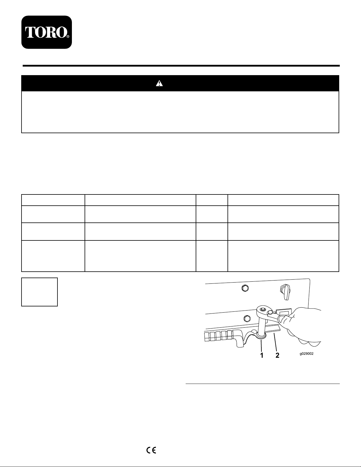
2.Removetheboltlocatednexttotherightswelllatch
(Figure1).
©2015—TheT oro®Company
8111LyndaleAvenueSouth
Bloomington,MN55420
Registeratwww.T oro.com.
Figure1
1.Removethisbolt.2.Rightswelllatch
OriginalInstructions(EN)
PrintedintheUSA
AllRightsReserved
*3395-202*A
Page 2
3.Releasethe2swelllatches(Figure2).
Figure4
1.Lowercotterkey
Figure2
1.Swelllatch
4.Graspthehandleandpulltherearaccesscoverupand
thenbacktoswingitopen.
2.Rearaccesscover
2
RemovingtheExisting
Fuel-StopSolenoidand
Speed-ControlPlate
NoPartsRequired
RemovingtheExistingFuelStop
1.Removebothupperandlowercotterkeyssecuring
thesolenoid-stoparmtotheengine-stoplever(Figure
3andFigure4).
2.Separatethesolenoid-stoparmfromtheengine-stop
lever(Figure5).
Figure5
1.Engine-stoplever2.Washer
3.Discardthewasher(Figure5).
4.Removethenutsecuringthethrottle-cableswivelto
thespeed-controllever(Figure6).
1.Solenoid-stoparm
Figure3
2.Uppercotterkey
Figure6
1.Nut2.Throttlecableswivel
5.Disconnectthethrottle-cableswivelfromthe
speed-controllever.
2
Page 3
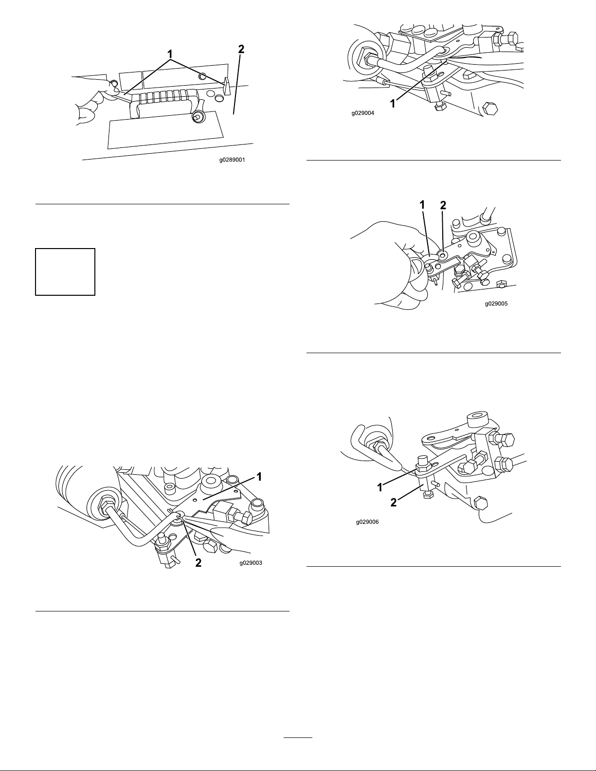
6.Removethe2boltsandnutssecuringthefuel-stop
solenoidtoitsmount(Figure7).
Figure7
1.Bolt2.Fuel-stopsolenoid
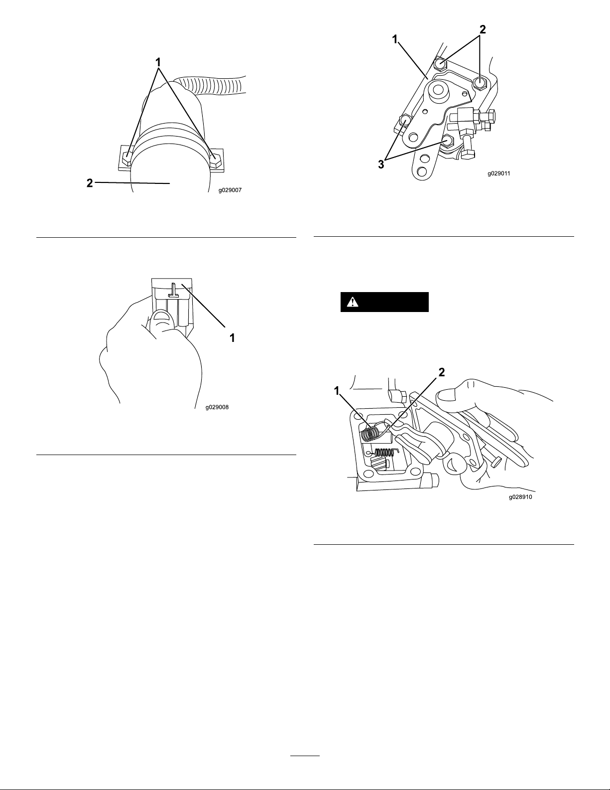
1.Speed-controlplate
2.Boltwithwasher
Figure9
3.Boltwithoutwasher
7.Unplugthefuel-stopsolenoidwiringharnessfromthe
mainwireharnessplugconnector(Figure8).
Figure8
1.Fuel-stopsolenoidwireharness
8.Slidethefuel-stopsolenoidbackandthenupandout
fromitsmountinglocation.
RemovingtheExistingSpeed-Control
Plate
2.Pulloutthespeed-controlplateenoughtodisconnect
thegovernorspringfromthegovernorlever(Figure
10).
CAUTION
Disconnectthegovernorspringfromthe
governorleverpriortocompletelyremoving
thespeedcontrolplate.
Figure10
1.Governorspring2.Governorlever
1.Removethe4boltsand2washerssecuringtheexisting
speed-controlplatetotheengine(Figure9).
Note:Retainthehardware.Y ouwillusethemto
installthereplacementspeed-controlplate.
3.Completelyremovethespeed-controlplatefromthe
engine.
3
Page 4

3
InstallingtheKit
Partsneededforthisprocedure:
1
Speedcontrolplate
1Fuelstopstolenoid
2Bolt
1Jumperharness
4.Connectthejumperharnesstothefuel-stopsolenoid
plugconnector(Figure12).
Figure12
InstallingtheNewSpeed-ControlPlate
1.Hookthegovernorspringtothegovernorleverofthe
replacementspeed-controlplate(seeFigure10).
2.Installthespeed-controlplateusingtheoriginal4bolts
and2washers(seeFigure9).
Note:Ensurethewashersareinstalledwiththebolts
asshowninFigure9
3.Torquetheboltsto8.1N-m(6ft-lb).
InstallingtheFuel-StopSolenoid
1.Removetheairltercover.
2.Positionthereplacementfuel-stopsolenoidand
looselysecureitwith2bolts(Figure11).
1.Fuel-stopsolenoidplug
connector
5.Routetheotherendofthejumperharnessunder
theradiatorhoseandthenplugitintothemainwire
harness(Figure13).
1.Radiatorhose2.Jumperharness
6.Positionthefuel-stopsolenoidsotheplungerpin
alignswiththeengine-stop-leverhook(Figure14).
2.Jumperharness
Figure13
Figure11
1.Replacementfuel-stop
solenoid
3.Applythreadlockertothe2bolts.
2.Hole
Figure14
1.Plungerpin2.Engine-stop-leverhook
4
Page 5

7.Manuallypushthesolenoidplungerawayfromthefuel
distributoruntilitisfullyextendedfromitshousing
(Figure15).
Figure15
1.Solenoidplunger3.Stopleverrestingagainst
2.Fueldistributor
thefuel-distributorhousing
stop
8.InstalltheignitionkeyandturntheswitchtotheON
position,butdonotstartthemachine.
9.Stopmanuallyextendingthesolenoidplunger.
Note:Theholdcoilwillkeepthesolenoidplunger
extendedelectrically.
10.Withthesolenoidplungerelectricallyextended,slide
theenginestopsolenoidtowardthefueldistributor
untiltheenginestopleverrestsagainstthestoponthe
fuel-distributorhousing(Figure15).
11.Holdthefuel-stopsolenoidinposition,applythread
lockertothe2boltsecuringthefuel-stopsolenoid,and
torquethemto19N-m(14ft-lb).
Note:Ensurethatthefuel-stopsolenoidisinthe
samepositionaftertheadjustmentmadeinstep6.
12.TurntheignitionkeytotheOFFposition.
13.Installtheairltercover.
14.Startandrunthemachinetoconrmproperoperation.
15.Swingtherearaccesscoverup,seatitintoplace,and
securewiththe2swelllatchesandbolt.
5
Page 6

Notes:
6
Page 7

Notes:
7
Page 8

 Loading...