

FormNo.3383-464RevA
Long-RangeExit-SideLockoutKit
2024or4045DirectionalDrill
ModelNo.130-4454
Operator'sManual
FCCStatements
Introduction
15.19–TwoPartWarning
Theexit-sidelockouttransmitterandreceiveris
designedtoremotelystopandlockouttheusercontrols
ofadirectionaldrill.
Readthisinformationcarefullytolearnhowtooperateand
maintainyourmachineproperlyandtoavoidinjuryand
equipmentdamage.Youareresponsibleforoperatingthe
machineproperlyandsafely.
YoumaycontactT orodirectlyatwww .Toro.comforproduct
andaccessoryinformation,helpndingadealer,ortoregister
yourproduct.
Thismanualidentiespotentialhazardsandhassafety
messagesidentiedbythesafetyalertsymbol(Figure1),
whichsignalsahazardthatmaycauseseriousinjuryordeath
ifyoudonotfollowtherecommendedprecautions.
Figure1
1.Safetyalertsymbol
Thismanualuses2wordstohighlightinformation.
Importantcallsattentiontospecialmechanicalinformation
andNoteemphasizesgeneralinformationworthyofspecial
attention.
ThisproductcomplieswithallrelevantEuropeandirectives.
Fordetails,seetheseparateproduct-specicDeclarationof
Conformity(DOC)sheet.
ThisdevicecomplieswithPart15oftheFCCrules.Operation
issubjecttothefollowingtwoconditions:
(1)Thisdevicemaynotcauseharmfulinterferenceand
(2)Thisdevicemustacceptanyinterferencereceived,including
interferencethatmaycauseundesiredoperation.
15.21–UnauthorizedModication
NOTICE:Themanufacturerisnotresponsibleforany
unauthorizedmodicationstothisequipmentmadebytheuser.
Suchmodicationscouldvoidtheuser’sauthoritytooperate
theequipment.
15.105(b)–Note:
Thisequipmenthasbeentestedandfoundtocomplywith
thelimitsforaClassBdigitaldevice,pursuanttoPart15
oftheFCCRules.Theselimitsaredesignedtoprovide
reasonableprotectionagainstharmfulinterferenceina
residentialinstallation.Thisequipmentgenerates,usesand
canradiateradiofrequencyenergyand,ifnotinstalledand
usedinaccordancewiththeinstructions,maycauseharmful
interferencetoradiocommunications.However,thereis
noguaranteethatinterferencewillnotoccurinaparticular
installation.Ifthisequipmentdoescauseharmfulinterference
toradioortelevisionreception,whichcanbedeterminedby
turningtheequipmentoffandon,theuserisencouragedto
trytocorrecttheinterferencebyoneormoreofthefollowing
measures:
•Reorientorrelocatethereceivingantenna.
•Increasetheseparationbetweentheequipmentandreceiver.
•Connecttheequipmentintoanoutletonacircuitdifferent
fromthattowhichthereceiverisconnected.
•Consultthedealeroranexperiencedradio/TVtechnicianfor
help.
Thisproductmaycontainmaterialthatmaybehazardousto
humanhealthandtheenvironment.IncompliancewithEU
Directive2002/96/EConWasteElectricalandElectronic
Equipment(WEEE):
•Donotdisposeoftheproductasunsortedmunicipal
waste.
•Thisproductshouldberecycledinaccordancewith
localregulations.Contactlocalauthoritiesfordetailed
information.
•Thisproductmaybereturnabletothedistributorfor
recycling.Contactyourdistributor/dealerfordetails.
©2014—TheToro®Company
8111LyndaleAvenueSouth
Bloomington,MN55420
Registeratwww.T oro.com.
IndustryCanadaStatement
ThisdevicecomplieswithCanadianRSS-210.
Theinstallerofthisradioequipmentmustensurethatthe
antennaislocatedorpointedsuchthatitdoesnotemitRFeld
inexcessofHealthCanadalimitsforthegeneralpopulation;
consultSafetyCode6,obtainablefromHealthCanada’s
websitewww.hc-sc.gc-ca/rpb.
ThisdevicecomplieswithIndustryCanadalicence-exempt
RSSstandard(s).Operationissubjecttothefollowingtwo
conditions:(1)thisdevicemaynotcauseinterference,and(2)
thisdevicemustacceptanyinterference,includinginterference
thatmaycauseundesiredoperationofthedevice.
OriginalInstructions(EN)
PrintedintheUSA.
AllRightsReserved
*3383-464*A
Safety
Improperlyusingormaintainingthisequipmentcan
resultininjury.Toreducethepotentialforinjury,
complywiththesesafetyinstructions.Torotestedthis
equipmentforreasonablysafeservice;however,failureto
complywiththefollowinginstructionsmayresultinpersonal
injury.
Toensuremaximumsafety,bestperformance,and
togainknowledgeoftheproduct,itisessentialthat
youandanyotheroperatorreadandunderstandthe
contentsofthismanualbeforeusingthisproduct.Pay
particularattentiontothesafetyalertsymbol(Figure1),
whichmeansCaution,Warning,orDanger—“personal
safetyinstruction.”Readandunderstandtheinstruction
becauseithastodowithsafety .Failuretocomplywith
theinstructionmayresultinpersonalinjury.
•Failuretoabidebytheseprecautionsmayresultin
equipmentfailureandpersonalinjury.
•Useandmaintainproperwiring.Improper,loose,and
frayedwiringcancausesystemfailure,equipmentdamage,
andintermittentoperation.
•Changesormodicationsmadetoequipmentnot
expresslyapprovedbythemanufacturerwillvoidthe
warranty.
•Owner/operatorsoftheequipmentmustabidebyall
applicableFederal,State,andLocallawsconcerning
installationandoperationoftheequipment.
•Makesurethatthemachineryandsurroundingareais
clearbeforeoperating.Donotactivatetheremotecontrol
systemuntilcertainthatitissafetodoso.
•Turnoffthehandheldremoteandremovepowerfrom
thebaseunitbeforeattemptinganymaintenance.This
willpreventaccidentaloperationofthecontrolled
machinery.
•PowerisremovedfromtheBaseUnitbydetachingthe
12-pincablefromthebaseunitconnectorP1,orby
removingthesourcepowerfromthecircuit.
•Useadampclothtokeepunitsclean.Removemud,
concrete,dirt,etc.afterusetopreventobstructingor
cloggingthebuttons,levers,wiring,andswitches.
•Donotallowliquidtoenterthehandheldorbaseunit
enclosures.Donotuseahighpressurewashertoclean
theequipment.
•Disconnecttheradiobaseunitbeforeweldingonthe
machine.Failuretodisconnectthebaseunitmayresultin
destructionofordamagetothebaseunit.
•Operateandstoreunitsonlywithinthespecied
operationandstoragetemperaturesdenedinthis
document.
Setup
InstallingtheReceiver
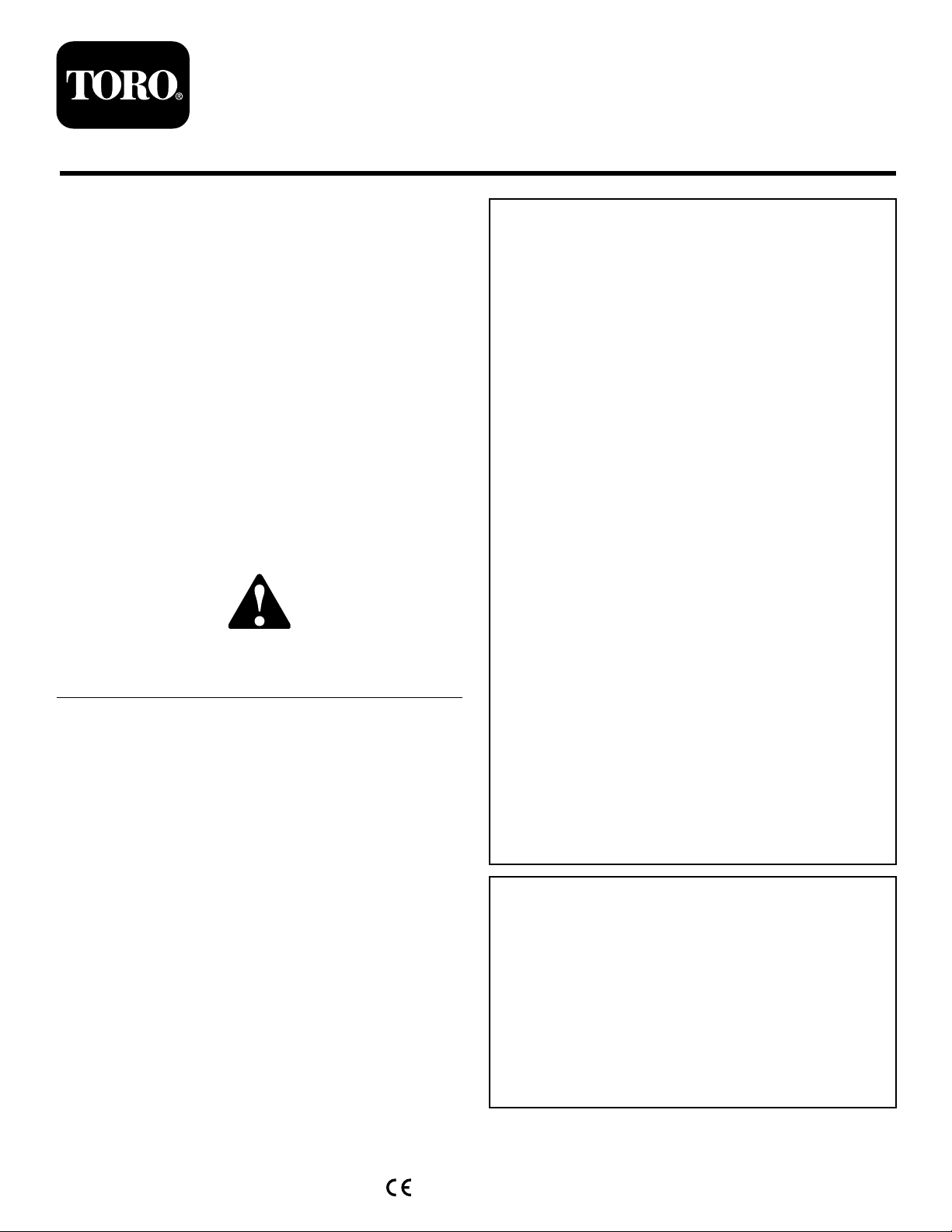
Removethepanelonthecontroltowernexttotheoperator’ s
seat(Figure2).
Figure2
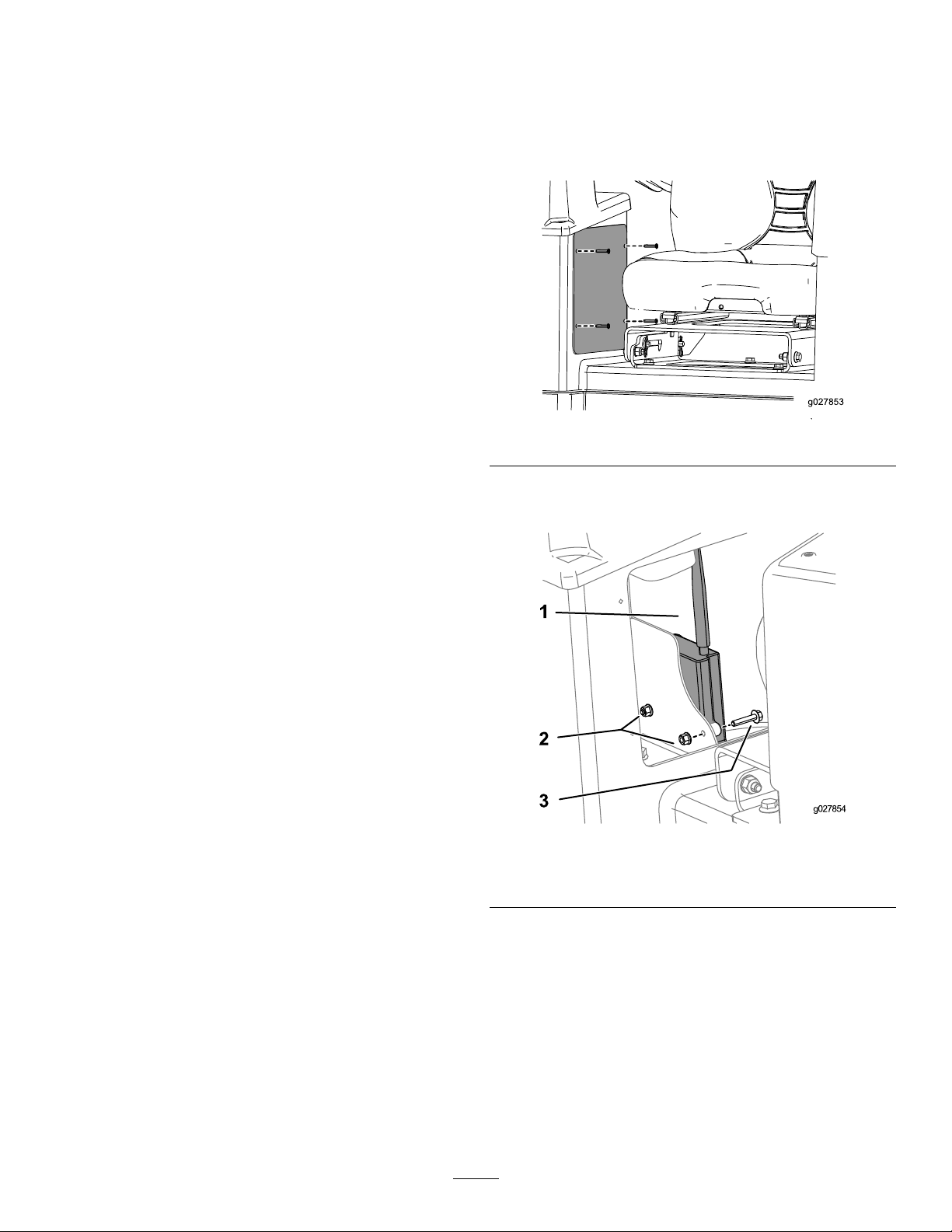
Removethereceiverthatiscurrentlyinstalledandinstallthe
newreceiverasshowninFigure3.
Figure3
1.Receiver3.Bolts
2.Nuts
2
ProductOverview
Controls
Exit-Side-LockoutSystem
Theexit-side-lockoutsystemprovidestheindividualsworking
aroundthemachinewithameanstodisablethedrillpipe
fromrotatingandthrusting.
Thissystemconsistsofareceivermountedonthemachine
andatransmitter(Figure4)thatmustbeheldbyadesignated
individualworkingaroundthemachine.
•Placingawiperonthedrillpipe
•Whenthehandheldtransmitteroperatoridentiesa
problemrequiringimmediateshutdownofdrilling
Whenitissafetoresumedrilling,theindividualholdingthe
transmittercanpresstheUnlockDrill(On)button.This
buttonsendsasignaltothereceiverthatallowsthemachine
operatortoresetthesystemandrestorethethrustandrotary
functions.
Specications
HandheldUnit
Batteries3AAA
Autoshutdown
Lowbatterywarning3.2Vandbelow
LowbatteryshutdownAt3.2VtheBAindicator
Operatingtemperature-20to55degreesC(-4to131
Storagetemperature-40to55degreesC(-40to
Radiofrequency
RadioRFpower50mW
RadiolicenseNotrequired
Modulation
AntennaInternal
After2hoursofinactivity
lightwillashrapidlyfor30
secondspriortoshutdown.
degreesF)
131degreesF)
2405to2480MHz
DSSS
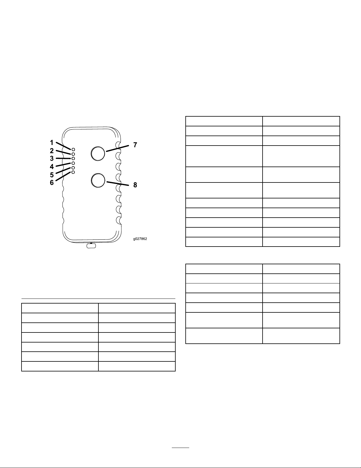
Figure4
1.TXindicatorlight5.A1indicatorlight
2.RXindicatorlight6.A2indicatorlight
3.ERindicatorlight
4.BAindicatorlight
LabelFunction
TXTransmit
RXReceive
ERError
BALowBattery
A1Auxiliary1
A2Auxiliary2
7.Onbutton
8.Offbutton
TheindividualholdingthetransmittercanpushtheLock
Drill(Off)buttontostopthedrillrotationandthrust.This
isprimarilyusedtostop/lockoutthedrilloperationsinthe
followingsituations:
•Wheninstallingorremovingadrillheadorreamer
•Wheneversomeoneneedstoapproachthedrillpipeor
headanywhereinfrontofthemachine
BaseUnit
Radiofrequency
RadioRFpower100mW
RadiolicenseNotrequired
Modulation
AntennaExternal
Operatingtemperature-20to55degreesC(-4to131
Storagetemperature-40to55degreesC(-40to
2405to2480MHz
DSSS
degreesF)
131degreesF)
3
Operation
HandheldIndicatorLights
Thefollowingtableliststhevariousstatesoftheindicator
lightsonthehandheldtransmitter(Figure4)andtheir
meanings:
IndicatorLightState
TheTXindicatorlightisdim
andblinkingrapidly.
TheTXindicatorlightisbright
andblinkingrapidly.
TheRXindicatorlightisbright
andblinkingrapidly.
TheERindicatorlightislit
solid.
TheBAindicatorlightis
blinkingslowly .
Meaning
Thehandledunitis
transmittingtothereceiver.
Abuttonisactiveonthe
handheldunit.
Thehandheldunitisreceiving
transmission.
Thereisanerrorwiththe
transmission.
Thebatteriesarelow.See
ReplacingtheTransmitter
Batteries(page4)
ReplacingtheTransmitter Batteries
1.Loosenthefourscrewssecuringthebatterycover
(Figure5).
Figure6
1.Handheldtransmitter2.Batterycover
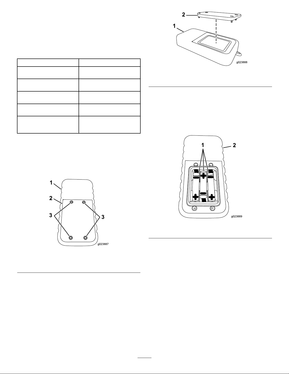
3.Removetheexistingbatteries.
4.Install3new,AAAbatteriesintheorientationshown
inFigure7.
Important:Ensurethatyouinstallthebatteries
inthecorrectpolarityorientationoryoucould
damagethetransmitter.
Figure5
1.Handheldtransmitter
2.Batterycover
2.Removethecover(Figure6).
Figure7
1.Handheldtransmitter2.AAAbatteries
5.Replacethecoverandsecureitwiththescrewremoved
previously.
3.Screws
Tightenthescrewsenoughtoensurethatthesealing
gasketiscompressed,butdonotovertightenthem.
4

AssociatingtheHandheld TransmitterwiththeBaseUnit
complete,theYellowlightturnsoff,theRedlight
beginsashing,andtheGreenlightilluminates.All
lightsremainasmentioneduntilyoureleasethebutton.
Ifthehandheldtransmittereverstopscommunicatingwith
thebaseunit,orifyoureplaceitwithanewtransmitter,you
needtoassociatethetransmittertothebaseunitasfollows:
1.Ensurethatthemachineisturnedoff.
2.Ensurethatthehandheldtransmitterisnotactive(i.e.,
nolightsareon).
3.Standneartherearcontrolpanelofthemachine.
4.SimultaneouslypressandholdtheOnandOffbuttons.
Allofthelightswillilluminate.
5.ContinueholdingthebuttonsuntiltheTXlightbegins
ashing.
6.ContinueholdingtheOnandOffbuttonsandturnon
themachinetopowerthebaseunit.
Thebaseunitandhandheldestablishacommunication
linkwhileyouholdthebutton.Oncetheprocessis
complete,allofthelightswillash.
7.Releasethebuttons.
DisassociatingallHandheld
8.ReleasetheOffbutton.
TheRedlightturnsoffandtheGreenlightashesfor
afewseconds.
TransmittersfromtheBase
Unit
Important:Completingthisprocedurewilldisassociate
alltransmittersfromthebaseunit,whichwillneedtobe
associatedagainbeforetheywillfunction.
1.Ensurethatthemachineisturnedoff.
2.Ensurethatthehandheldtransmitterisnotactive(i.e.,
nolightsareon).
3.Standneartherearcontrolpanelofthemachine.
4.SimultaneouslypressandholdtheOnandOffbuttons.
TheGreenlightilluminates.
5.ContinueholdingthebuttonsuntiltheYellowlight
beginsashing,thenreleasethebuttons.
TheRedlightbeginsashingallowingyou2seconds
topressthenextbutton.
6.PressandholdtheOffbutton
TheRedlightturnsoffandtheGreenandY ellow
lightsilluminate.
Important:Ifyoudonotpressthisbuttonwithin
2seconds,youwillhavetostartthisprocedure
overagain.
7.ContinueholdingtheOffbuttonandturnonthe
machinetopowerthebaseunit.
Thebaseunitandhandheldestablishacommunication
linkwhileyouholdthebutton.Oncetheprocessis
5

Notes:
6

Notes:
7


WSMB-7588
JEM TECHNICAL
™
Engineered System Manual 2-3
2013 Cervis, Inc .

WSMB-7588 JEM Technical
Industry Canada Statement
Industry Canada Statement
RoHS Compliance Statement
IC Unlicensed Devices EIRP Statements for Removable Antennas
gain maximal indiqué, sont strictement interdits pour l'exploitation de l'émetteur.
FCC Statements
15.19 – Two Part Warning
This device complies with Part 15 of the FCC rules. Operation is subject to the following two conditions:
(1) This device may not cause harmful interference and
(2) This device must accept any interference received, including interference that may cause undesired operation.
15.21 – Unauthorized Modification
NOTICE: The manufacturer is not responsible for any unauthorized modifications to this equipment made by the user. Such modifications could
void the user’s authority to operate the equipment.
15.105(b) – Note:
Note: This equipment has been tested and found to comply with the limits for a Class B digital device, pursuant to part 15 of the FCC Rules. These limits are
designed to provide reasonable protection against harmful interference in a residential installation. The equipment generates, uses and can radiate radio
frequency energy and, if not installed and used in accordance with the instructions, may cause harmful interference to radio communications. However,
there is no guarantee that interference will not occur in a particular installation. If this equipment does cause harmful interference to radio or television
reception, which can be determined by turning the equipment off and on, the user is encouraged to try to correct the interference by one or more of the
following measures:
—Reorient or relocate the receiving antenna.
—Increase the separation between the equipment and receiver.
—Connect the equipment into an outlet on a circuit different from that to which the receiver is connected.
—Consult the dealer or an experienced radio/TV technician for help.
This device complies with Canadian RSS-210.
The installer of this radio equipment must ensure that the antenna is located or pointed such that it does not emit RF field in excess of Health Canada limits for
the general population; consult Safety Code 6, obtainable from Health Canada’s website www.hc-sc.gc-ca/rpb.
Le présent appareil est conforme aux CNR d'Industrie Canada applicables aux appareils radio
exempts de licence. L'exploitation est autorisée aux deux conditions suivantes : (1) l'appareil ne doit pas produire de brouillage, et (2) l'utilisateur de l'appareil
doit accepter tout brouillage
radioélectrique subi, même si le brouillage est susceptible d'en compromettre le fonctionnement.
This device complies with Industry Canada licence-exempt RSS standard(s). Operation is subject to the following two conditions: (1) this device may not cause
interference, and (2) this device must accept any interference, including interference that may cause undesired operation of the device.
Le présent appareil est conforme aux CNR d'Industrie Canada applicables aux appareils radio exempts de licence. L'exploitation est autorisée aux deux
conditions suivantes : (1) l'appareil ne doit pas produire de brouillage, et (2) l'utilisateur de l'appareil doit accepter tout brouillage radioélectrique subi, même si
le brouillage est susceptible d'en compromettre le fonctionnement.
Cervis, Inc. complies with the requirements of Restriction of Hazardous Substances (RoHS/WEEE) Specification based on in-house practice and
declaration of compliance from our vendors. For additional information concerning RoHS compliance, please contact Cervis, Inc. at:
CERVIS, In c .
170 Thorn Hill Road Warrendale, PA 15086
Phone: 724.741.9000 Fax: 724.741.9001
This product may contain material that may be hazardous to human health and the environment. In compliance with EU
Directive 2002/96/EC on Waste Electrical and Electronic Equipment (WEEE):
Do not dispose of the product as unsorted municipal waste.
This product should be recycled in accordance with local regulations. Contact local authorities for detailed
information.
This product may be returnable to the distributor for recycling. Contact your distributor for details.
Part 1: Under Industry Canada regulations, this radio transmitter may only operate using an antenna of a type and maximum (or lesser) gain
approved for the transmitter by Industry Canada. To reduce potential radio interference to other users, the antenna type and its gain should be so
chosen that the equivalent isotropically radiated power (e.i.r.p.) is not more than that necessary for successful communication.
Conformément à la réglementation d'Industrie Canada, le présent émetteur radio peut fonctionner avec une antenne d'un type et d'un gain maximal (ou
inférieur) approuvé pour l'émetteur par Industrie Canada. Dans le but de réduire les risques de brouillage radioélectrique à l'intention des autres utilisateurs, il
faut choisir le type d'antenne et son gain de sorte que la puissance isotrope rayonnée équivalente (p.i.r.e.) ne dépasse pas l'intensité nécessaire à
l'établissement d'une communication satisfaisante.
Part 2: This radio transmitter (LOBSRF-305) has been approved by Industry Canada to operate with the antenna type listed below with the
maximum permissible gain and required antenna impedance for each antenna type indicated. Antenna types not included in this list, having a gain
greater than the maximum gain indicated for that type, are strictly prohibited for use with this device.
Le présent émetteur radio (LOBSRF-305) a été approuvé par Industrie Canada pour fonctionner avec les types d'antenne énumérés ci-dessous et ayant un
gain admissible maximal et l'impédance requise pour chaque type d'antenne. Les types d'antenne non inclus dans cette liste, ou dont le gain est supérieur au

Engineered System Manual
iii
Table of Contents
List of Figures ............................................................................................................................. iii
List of Tables ............................................................................................................................... iii
Cervis Inc. Safety Precautions .................................................................................................. iv
1.0 WSMB-7588 System List of Equipment ............................................................................. 1
2.0 BU-2H06D-7588 Mounting ................................................................................................... 2
3.0 Cable Wiring Diagram .......................................................................................................... 3
4.0 OO-2H02-7588 Handheld Remote Details .......................................................................... 4
4.1 OO-2H02-7588 Remote Buttons and LEDs ..................................................................... 4
4.2 OO-2H02-7588 Turn ON and Turn OFF ........................................................................... 5
4.3 OO-2H02-7588 Handheld Remote Battery Installation .................................................. 5
4.4 Associate Handheld and Base Unit ................................................................................ 6
4.5 Low Battery ....................................................................................................................... 6
5.0 BU-2H06D-7588 Base Unit Details ...................................................................................... 7
5.1 BU-2H06D-7588 Hardware Configuration ....................................................................... 7
5.2 BU-2H06D-7588 Safety Link ............................................................................................. 7
5.3 BU-2H06D-7588 Channel Configuration Details ............................................................ 7
6.0 SmaRT System WSMB-7588 Specifications ...................................................................... 8
6.1 OO-2H02-7588 Handheld Remote Specifications .......................................................... 8
6.2 BU-2H06D-7588 Base Unit Specifications ...................................................................... 9
6.3 BU-2H06D-7588 (BU-2H06D-EXT) Antenna List ............................................................. 9
Appendix A: Exposure to Radio Frequency Energy .............................................................. 10
Appendix B: Agency Identificatio n L abel Locations .............................................................. 10
History Table .............................................................................................................................. 11
List of Figures
Figure 1. WSMB-7588 System Diagram ....................................................................................... 1
Figure 2. BU-2H06D-7588 Mounting Details ................................................................................ 2
Figure 3. P1 Connector Wiring Dia gram ...................................................................................... 3
Figure 4. OO-2H02-7588 Handheld Remote ................................................................................. 4
Figure 5. OO-2H02-7588 Handheld Remote Battery Installation ............................................... 5
Figure 6. Associate Handheld Remote to Base Unit .................................................................. 6
Figure 7. Agency Identification Label Locations ...................................................................... 10
List of Tables
Table 1. WSMB-7588 System List of Equipment ......................................................................... 1
Table 2. OO-2H02-7588 Handheld Remote LEDs ........................................................................ 4
Table 3. OO-2H02-7588 Handheld Remote LED Diagnostic Information .................................. 4
Table 4. BU-2H06D-7588 Base Unit Hardware Configuration Details ....................................... 7
Table 5. BU-2H06D-7588 Base Unit Channel Configuration Details ......................................... 7
Table 6. OO-2H02-7588 Handheld Remote Specifications ......................................................... 8
Table 7. BU-2H06D-75 88 Base Un it Spe cificat io n s ..................................................................... 9
Table 8. BU-2H06D-7588 (BU-2H06D-EXT) External Antenna Details ....................................... 9
2013 Cervis, Inc.

WSMB-7588 JEM Technical
iv
Cervis Inc. Safety Precautions
Read and follow all instructions .
Failure to abide by Safety Precautions may result in equipment failure, loss of
authority to operate the equipment, and personal injury.
Use and maintain proper wiring. Follow equipment manufacturer instructio n s.
Improper, loose, and frayed wiring can cause system failure, equipment damage, and
intermittent operation.
Changes or modifications made to equipment not expressly approved by the
manufacturer will void the warran ty.
Owner/operators of the equipment must abide by all applicable Federal, State, and
Local laws concerning installation and operation of the equipment. Failure to comply
could result in penalties and could void user authority to operate the equipment.
Make sure that the machinery and surrounding area is clear before operating. Do not
activate the remote control system until certain that it is safe to do so.
Turn off the handheld remote and remove power from the base unit before attempting
any maintenance. This will prevent accidental operation of the controlled machinery.
Power can be removed from the Base Unit by detaching the 12-pin cable from the
base unit connector P1, or by removi n g th e source power from the circuit.
Use a damp cloth to keep units clean. Remove mud, concrete, dirt, etc. after use to
prevent obstructing or clogging the buttons , levers, wiring, and switches.
Do not allow liquid to enter the handheld o r base unit enclosures. Do not use high
pressure equipment to clean the ha n d h eld remote or base unit.
Disconnect the radio base unit befor e welding on the machine. Failure to disconn ect
the base unit may result in destruction of or damage to the base unit.
Operate and store units only within the specified operation and storage temperatures
defined in Heading
6.0 SmaRT System WSMB-7588 Specifications of this document.
WSMB-7588_ESM 2-3

Engineered System Manual
Qty
Item
Part #
Description
to loads
BB3-07 antenna
1.0 WSMB-7588 System List of Equipmen t
Note: It is possible to order the system with one part number. Specify WSMB-7588 in the
purchase order to receive the parts listed in the table below. If an individual part needs to be
ordered, use the part number listed in the table below.
Table 1. WSMB-7588 System List of Equipment
1
1
1
1
OO-2H02-7588 OO-2H02 Handheld, 2-button, 2.4GHz
BU-2H06D-7588 BU-2H06D-EXT Base unit, 6-FET, 2.4GHz, external antenna
BB3-07 BB3-07 Antenna, 2.4GHz, swivel
J5-02 J5-02 Antenna extension cable
OO-2H02-
7588
Remote
J5-02 extension cable
BU-2H06D-7588
Base Unit
Figure 1. WSMB-7588 System Diagram

WSMB-7588 JEM Technical
2
36mm (1.4”)
7.4mm
133mm (5.25”)
118mm (4.7”)
102mm (4”) centers
115mm (4.57”)
42.69mm (1.68”)
2.0 BU-2H06D-7588 Mounting
Note: The BU-2H06D-7588 must be mounted so that connector P1 is facing down to guard
against water entering the wiring harness.
Note: The BU-2H06D-7588 uses an RP-TNC connection for the antenna. If extending the
antenna from the base unit, only a Cervis recommended extension cable kit should be used.
Figure 2. BU-2H06D-7588 Mounting Details
(0.29”) dia.
WSMB-7588_ESM 2-3

Engineered System Manual
3
(12) -VDC
(10) M5: not used
(9) RS-232 COM (unused)
(8) RS-232 RX (unused)
(7) RS-232 TX (unused)
(6) M4: not used
(5) M3: OK to Drill Green LED (LT04)
(4) M2: OK to Reset Amber LED (LT03)
(3) M1: HH Low Battery Red LED (LT04)
(2) +VDC
(11) M6: Switch to Ground Reset Input
(1) +VDC
+VDC Battery/Power Supply
–VDC Battery/Power Supply
3.0 Cable Wiring Diagram
Note: Unused wires should never be tied together. Cervis recommends cutting the
wires close to the P1 connector or cutting the unused wires back and taping the
end of each to minimize transient/rad io interference.
Figure 3. P1 Connector Wiring Diagram
2013 Cervis, Inc.

WSMB-7588 JEM Technical
4
Button/LED
Label
Function
Condition
LED Information
Condition
LED Information
4.0 OO-2H02-7588 Handheld Remote Details
Figure 4. OO-2H02-7588 Handheld Remote
4.1 OO-2H02-7588 Remote Buttons and LEDs
Table 2. OO-2H02-7588 Handheld Remote LEDs
Button 1
Button 2
LED 1
LED 2
LED 3
LED4
LED5
LED6
Table 3. OO-2H02-7588 Handheld Remote LED Diagnostic Information
Handheld is
transmitting
Button active on
handheld
Handheld is receiving
Error
LED1 rapid blinking dim
LED1 rapid blinking
bright
LED2 rapid blinking
bright
LED3 lit solid
ON ON
OFF OFF
TX Transmit
RX Receive
ER Error
BA Low Battery
A1 Auxiliary 1
A2 Auxiliary 2
Low battery
A1 and A2
LED3 slow blinking
unused
WSMB-7588_ESM 2-3

Engineered System Manual
5
Cover screw
Sealing gasket
4.2 OO-2H02-7588 Turn ON and Turn OFF
ON – Press Button 1
OFF – Press and hold Button 2 for 4-seconds.
4.3 OO-2H02-7588 Handheld Remote Battery Installation
Handheld units are powered by three size AAA batteries. When installing batteries, be sure to
observe proper polarity as marked on the inside of the compartment to avoid damaging the unit.
To replace or install batteries in the handheld:
1. Remove the four small Phillips screws from the Battery Compartment cover and lift the cover
from the handheld.
2. If installing batteries in an empty battery compartment, install three fresh si ze AAA batteries.
Be sure to position the batteries as shown in Figure 5 below.
3. If replacing expired batteries, remove the old batteries and install three fresh size AAA
batteries. Be sure to position the batteries as shown in Figure 5 below.
4. Replace the compartment cover and tighten the four Phillips screws. These screws should
not be over-tightened, but they should be tight enough to assure the gasket provides a
proper seal.
Figure 5. OO-2H02-7588 Handheld Remote Battery Installation
Note: Cover screws must be tightened enough to ensure the sealing gasket is compressed.
Do not over-tighten the screws.
Be sure to observe proper polarity when placing batteries in the
handheld battery compartment.
2013 Cervis, Inc.

WSMB-7588 JEM Technical
6
4.4 Associate Handhel d a nd Ba s e Unit
The OO-2H02-7588 must establish communications with base unit BU-2H06D-7588 before the
system can be used. The OO-2H02-7588 handheld remote is associated to the system base unit
before leaving the factory. This is done using the Associate procedure. In situations where it is
necessary to re-establish handheld-to-base unit communications, the following Associate
procedure must be performed.
Associate Handheld Remote to Base Unit
1. Remove power from the base unit.
2. Stand near the base unit in unobstructed, clear line-of-sight with the handheld in hand.
3. Simultaneously press and hold buttons B1 and B2. All LEDs activate.
4. Continue to hold both buttons until the TX LED begins flashing.
5. Apply power to the base unit while continuing to hold the buttons. All LEDs flash, then all
activate.
6. Release both buttons.
The SmaRT System is ready for use with that particular handheld remote.
Figure 6. Associate Handheld Remote to Base Unit
4.5 Low Battery
At 3.5V the BAT LED begins flas hing. Appr ox im at ely 30 seconds later, the handheld shuts
down.
WSMB-7588_ESM 2-3

Engineered System Manual
7
Required Fields
Interface Description
Channel #
Type
Style
Custom Code Notes
5.0 BU-2H06D-7588 Base Unit Details
5.1 BU-2H06D-7588 Hardware Configuration
Table 4. BU-2H06D-7588 Base Unit Hardware Configuration Details
Control Power
Number of I/O Channels
Output Composition
Antenna Option
Frequency
Note: Input channels are active when the input is switched-to-ground (same potential
12VDC
6
FET
EXTERNAL
2.4GHz
as P1:12). For the input to be considered active, the voltage at the input channel must
be less than 1V relative to P1:12 for at least 100msec. For the input to be considered
inactive, the voltage at the input channel must be greater than 3V for the same
minimum amount of time. All input channels are equipped with internal pull-up
resistors. Therefore, when an input is disconnected from an input channel, the input is
considered inactive.
5.2 BU-2H06D-7588 Safety Link
SAFETY LINK ENABLED – In the event that the handheld and base unit lose communication,
the base unit will deactivate any active outputs. In the event that communication is reestablished, no active commands can be present in the initial communication in order for a link
to be established and for outputs to be affected by the handheld and by proxy in this application
the other base units. Safety Link is based on a five (5) second w indow – in the event that no
message is received from the handheld within five (5) seconds after receipt of the last valid
message, any active outputs will be disabled.
5.3 BU-2H06D-7588 Channel Configurati on Details
Table 5. BU-2H06D-7588 Base Unit Channel Configuration Details
M1
Transmitter Low Bat
(Red LED)
M2
OK to Reset
(Amber LED)
M3
OK to Drill (Green LED)
M4 (Not used)
M5 (Not used)
M6
Reset Input
Level
Output
Level
Output
Level
Output
Level
Level
Level
Input
Momentary Low Battery signal sent from HH
Latched ON B1
Latched OFF B2 OR Loss of link
Latched ON M2 AND M6 ACTIVE
Latched OFF HH OFF OR Loss of link
Momentary Switch to ground input from reset switch
(active for 30 seconds)
Active when<1, not active when >3
2013 Cervis, Inc.

WSMB-7588 JEM Technical
8
Item
Description
6.0 SmaRT System WSMB-7588 Specifications
6.1 OO-2H02-7588 Handheld Remote Specifications
Table 6. OO-2H02-7588 Handheld Remote Specifications
Power
Environment
Radio
Enclosure
V
in
Batteries
+3.6V to +4.5V
Three (3) AAA
Low Battery Warning 3.2V LED 3 flashes for 30 seconds prior
to shutdown
Inactivity Timeout Infinite
Operating Temp
-20°C to 55°C
(-4°F to 131°F)
Storage Temp
(-40°F to 131°F)
-40°C to 55°C
Humidity 0 to 100%
Frequency
2405-2480MHz
RF Power 50mW
License
License free certification pending
Modulation DSSS
Antenna Internal
Dimensions mm: 136.38 x 68.96 x 28.42
Inches: 5.37 x 2.68 x 0.92
Total Weight 200 gr./7.2 oz. (with lanyard)
Durability High Impact Polymer case
Polycarbonate faceplate
Impact absorbing bumper
Six Indicators
TX Green Transmit
RX Amber Receive
ER Red Error
BA Amber Low battery
A1 Auxiliary (unused)
A2 Auxiliary (unused)
Buttons
Pushbuttons Two (2)
Button Life 5-million operations (typical)
WSMB-7588_ESM 2-3

Engineered System Manual
9
Item Description
External Antenna
Manufacturer
Cervis BIN
6.2 BU-2H06D-7588 Base Unit Specifications
Table 7. BU-2H06D-7588 Base Unit Specifications
Power Vin
Radio Frequency
RF Power
License
Modulation
Antenna
Environment Operating Temp
Storage Temp
Humidity
Indicators (12) Unmarked
+V1 – +V3
RTX
RRX
Over Temp/Voltage
HTH
Under Current
Out
Not Used
In
Enclosure Dimensions
Durability
Weight
Outputs/Inputs FETs
+7 to +28VDC
2405-2480MHz
100mW
License Free certification pend ing
DSSS
External
-20°C to 55°C (-4°F to 131°F)
-40°C to 85°C (-40°F to 185°F)
0 to 100%
Input power polarity reversed when lit
OK when active solid
Blinking when transmitting
Active when receiving
Lit when temp or voltage exceeded
OK when blinking
Lit when current too low
Output active when lit
Unused
Input active when lit
mm: 133 x 118 x 36
inch: 5.24 x 4.65 x 1.42
High Impact Polymer
.24kg (0.5lbs)
Six, open drain
4A per channel,15A total @ 55ºC
6.3 BU-2H06D-7588 (BU-2H06D-EXT) Antenna List
Table 8. BU-2H06D-7588 (BU-2H06D-EXT) External Antenna Details
OMNI242R RFM BIN BB3-07
Note: Only the antenna recommended by Cervis, Inc. is to be used with the SmaRT base
unit.
2013 Cervis, Inc.

WSMB-7588 JEM Technical
10
Note: The base unit label position is identical for
Appendix A: Exposure to Radio Frequency Energy
SmaRT handheld remote units contain radio transceivers. When active, handheld remotes send
out radio frequency (RF) energy through its internal antenna.
For optimal performance and to ensure that human exposure to RF energy does not exceed the
recommended guidelines, always follow these instruction and precautions: When using the
handheld remote, hold the remote so that the top buttons are away from the body in the direction
of the base unit. Keep the remote when in use at least 15mm (5/8 inch) away from the body, and
only use carrying cases, belt clips, or holders that are approved by Cervis, Inc.
A SmaRT base unit when active sends out radio frequency (RF) through its external antenna.
Base units using an external antenna should be mounted to ensure the antenna is at least 20cm
away from the human body.
Appendix B: Agency Identification Label Locations
Figure 7. Agency Identification Label Locations
WSMB-7588_ESM 2-3
both internal antenna and external antenna base
units.

Engineered System Manual
11
Date
Action
By
This document is the property of Cervis, Inc. and cannot be copied, modified, e-mailed, or
without prior notification.
History Table
8/22/2012
8/23/2012
8/24/2012
3/14/13
10/31/13
11/11/2013
11/15/2013
12/16/2013
12/17/2013
Original from legacy WSMB-7588_ESM 0-0 AMD version GMS
MM and AMD review edits to 1-0 GMS
Change BU picture from 5-LED to 4-LED per AJ GMS
Change all BU-206F to BU-206D GMS
Changed all BU-206D to BU-2H06D TGM
Changed BU and OO pictures. Changed Specification to account for
additional LEDs on both units.
Change Safety Link timeout from 2 seconds. MAM
Added certified body materials GMS
Changed BU label. Changed BU RF power from 50mW to 100mW GMS
GMS
Visit our Web site at: www.cervisinc.com
2013 Cervis, Inc. All rights reserved. Content is subject to change without notice.
reproduced without the express prior written consent of Cervis, Inc.
Cervis, Inc. reserves the right to change this manual or edit, delete, or modify any information
2013 Cervis, Inc.
 Loading...