

Toro 130-2100 Installation Instructions

FormNo.3379-751RevB
FuelTankServiceKit
MB-1600MudBuggy
ModelNo.130-2100
InstallationInstructions
WARNING
CALIFORNIA
Proposition65Warning
ThisproductcontainsachemicalorchemicalsknowntotheStateofCaliforniato
causecancer,birthdefects,orreproductiveharm.
Installation
LooseParts
Usethechartbelowtoverifythatallpartshavebeenshipped.
ProcedureDescription
1
2
3
4
5
6
7
Nopartsrequired
Nopartsrequired
Nopartsrequired
Tank1
Fuelhose1
Hoseclamp2
Fuelcap/gauge
Nopartsrequired
Nopartsrequired
Venthose1
Hoseclamp2
Cabletie
Qty.
Use
–
–
–
1
–
–
1
Removetheenginecowl.
Drainthefueltank.
Removethefueltank.
Preparethefueltank.
Installthefueltank.
Installthefuelhose.
Replacetheventhose.
8
9
©2013—TheT oro®Company
8111LyndaleAvenueSouth
Bloomington,MN55420
Nopartsrequired
Nopartsrequired
Registeratwww.T oro.com.
–
–
Checkthefuelsystem.
Installtheenginecowl.
OriginalInstructions(EN)
PrintedintheUSA
AllRightsReserved
*3379-751*B

1
G019281
1
RemovingtheEngineCowl
NoPartsRequired
Procedure
1.Movethemachinetoalevelsurfaceandsettheparking
brake;refertotheOperator’ sManualforthemachine.
2.Positionthehopperinthedumpposition;refertothe
Operator’sManualforthemachine.
3.Shutofftheengine;refertotheOperator’ sManualfor
themachine.
4.Removethe4latchesthatsecuretheenginecowltothe
machineatthe4latchposts(Figure1).
Figure2
1.Forward
2.Shutoff-valveleverforthe
fueltank(Offposition)
2.Starttheengineandrunthemachineuntiltheengine
stops.
3.Rotatetheleverfortheengineswitchclockwisetothe
Stopposition,andallowtheenginetocool(Figure2).
4.Carefullyremovethespark-plugwirefromtheterminal
ofthesparkplug.(Figure3).
3.Engine-switchlever(Stop
position)
Figure1
1.Enginecowl3.Latch
2.Latchpost
5.Lifttheenginecowlupandremoveitfromthemachine
(Figure1).
2
DrainingtheFuelTank
NoPartsRequired
Procedure
1.Rotatetheleverforthetank-shutoffvalveforwardand
uptotheOffposition(Figure2).
Figure3
1.Spark-plugwire
5.Removethehoseclampandhosefromthebarbed
ttingatthetopoftheengineswitch(Figure2).
2
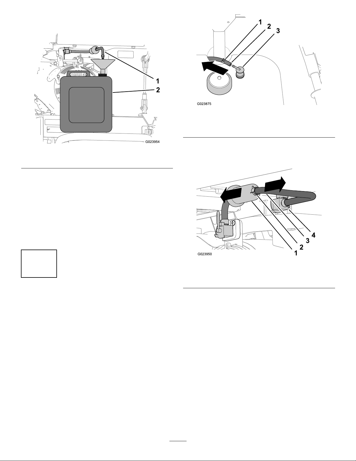
6.Alignthehoseintoanapprovedfuelcontainerwitha
26.5L(7USgallon)capacity(Figure4).
Figure5
1.Hoseclamp3.Ventvalve
2.Venthose
Figure4
1.Fuelhose2.Fuelcontainer
7.Rotatetheshutoffvalveforthefueltankbackand
downtotheOnposition(Figure2).
Note:Allowthefueltanktodraincompletely .
8.Installthehoseandhoseclampontothebarbedtting
atthetopoftheengineswitch(
Note:Ensurethatthebarbedttingisfullyinserted
intotheendofthefuelhoseandthattheclampis
centeredoverthebarbedareaofthetting.
Figure2).
3
RemovingtheFuelTank
NoPartsRequired
2.Removethehoseclampthatsecuresthefuelhoseto
thebarbedttinginthefuellter,andremovethehose
(Figure6).
Figure6
1.Fuellter
2.Hoseclamp
3.Removethe4ange-headboltsthatsecurethefuel
tanktothemachine,andremovethetankfromthe
machine(Figure7).
3.Fuelhose
4.Tank-shutoffvalve
Procedure
1.Removethehoseclampandtheventhosethatare
attachedtotheventvalveinthefueltank(Figure5).
Note:Becarefulwhenliftingthetankuptoensure
thattheshutoffvalveforthefueltankandthefuel
hosearecenteredwhilepassingthroughtheholeinthe
tank-supportplatefortheshutoffvalve.
3
 Loading...