

Page 1

FormNo.3394-287RevA
GlowPlugKit
TR-34DTrenchRoller
ModelNo.127-7527
InstallationInstructions
WARNING
CALIFORNIA
Proposition65Warning
ThisproductcontainsachemicalorchemicalsknowntotheStateofCaliforniato
causecancer,birthdefects,orreproductiveharm.
Forambientairtemperaturesof7°C(45°F)andbelow,theglowplugisrecommendedforstartingtheTrenchRoller.
Installation
LooseParts
Usethechartbelowtoverifythatallpartshavebeenshipped.
Description
Glowplug
Washers2
Nut1
Cableties
Glow-plugwiringharness
Relayswitch1
Spacer
Wiringharness1
Qty.
15
Use
1
1
1
Installtheglowplugkit.
©2015—TheToro®Company
8111LyndaleAvenueSouth
Bloomington,MN55420
Registeratwww.T oro.com.
OriginalInstructions(EN)
PrintedintheUSA.
AllRightsReserved
*3394-287*A
Page 2
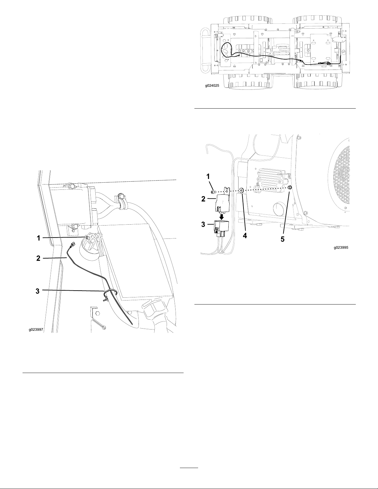
InstallingtheGlowPlugKit
1
2
3
g023997
g024025
1
2
3
4
g023995
5
PreparingtheMachine
1.Settheparkingbrake,openthehoodpanels,and
removetheright-sidepanel;refertotheOwner’ sManual
ofthemachine.
2.Disconnectthebattery.
RoutingtheWiringHarness
1.Removethewireconnectorfromtherearofthe
ignitionswitch.
2.Installthenon-insulatedterminalofthelongwireto
pocket8oftheconnector(Figure1).
Note:Ensurethatthewirelocksintotheconnector.
Ifthewiredoesnotlockinplace,rotatethewire180
degreesandinstallitintotheconnector.
Figure2
5.Removetheboltontherightsideoftheengine(Figure
3).
Figure3
1.Bolt
2.Relayswitch5.Locationtoinstalltherelay
3.Glow-plugwiringharness
4.Spacer
switch
Figure1
1.Locationtoinstallthewire
intotheconnector
2.Wire
3.Cabletie
3.Installthewireconnectortotherearoftheignition
switch.
4.Routethewirefromtheconnectoralongtheexisting
wiringharness,andsecurethewiretotheexisting
wiringharnessusingthecableties(Figure1andFigure
2).
Note:Ensurethatthewiredoesnotrubagainstany
sharpobjects.
6.Connecttheglow-plugwiringharnessblocktothe
relayswitchandsecuretherelayswitchontotheengine
usingtheboltpreviouslyremovedandthespacer,as
showninFigure3.
7.Removethenutonthestartersolenoid,placethe
shortestwireontothebolt,andinstallthenut(Item
2inFigure4).
2
Page 3

g023996
5
1
2
3
4
Figure4
g023993
1
2
3
4
g023994
3
5
InstallingtheGlowPlug
1.Removetheplugttingatthefrontoftheintake
manifoldoftheengine(Figure5).
1.Longestwireonthe
glow-plugwiringharness
connectedtotheglowplug
2.Locationtoinstallthe
mediumwireonthe
glow-plugwiringharness
3.Locationtoinstallthe
shortestwire
4.Connectoronthe
glow-plugwiringharness
connectedtothe
connectorofthewire
thatisroutedtotherearof
theignitionswitch
5.Connectoronwirebeing
routedfromtheignition
switch
8.Removethenutonthevoltageregulator,placethe
mediumwireontothebolt,andinstallthenut(Item
3inFigure4).
9.Connectthewirewiththeplasticconnectortothewire
thatisroutinguptotherearoftheignitionswitch
(Item4inFigure4).
10.Routethelongestwirefromtheglow-plugwiring
harnesstheexistingwiringharness,andsecurethewire
totheharnessusingthecableties.
11.SeeInstallingtheGlowPlug(page3)toconnectthe
longestwiretotheglowplug.
Figure5
2.Separatethewasherfromtheplugttingandinstallit
ontothepre-heaterelement.
3.Installtheglowplug,2washers,thelongestwire
comingfromtherelaywiringharnessandthenutas
showninFigure6.
1.Washer(previously
attachedtotheplug
tting)
2.Glowplug
3.Washer
Figure6
4.Longestwirefromthe
relaywiringharness
5.Nut
4.Connectthebatteryandclosethehood.
3
Page 4

Operation
g028261
1 2
3 4 5
6 7
StartingtheMachine
1.TurnthekeytotheRunpositionandwaitforthe
voltagethatisdisplayedonthescreentodropandraise
backup(Figure7).
Figure7
1.Information5.Start
2.Off
3.Run7.Key
4.Glow-plug/preheat
location
6.Keyswitch
2.TurnandholdthekeyinbetweentheRunandStart
positionsfor45seconds(Figure7).
Note:Thedisplaywillshutoffafter10secondsbut
thepreheaterwillcontinuetofunction.
Note:Thevoltagewilldropto0.5to1.0voltswhile
preheating.
3.TurnthekeytotheOffpositionthentotheRun
position.
4.TurnandholdthekeyinbetweentheRunandStart
positionsfor3to4seconds.
5.TurnthekeytotheStartposition(Figure7).
Note:Theengineshouldcrankformorethan1
second.Iftheenginedoesnotcrank,turnthekeyrst
totheOffpositionthentotheRunpositionthento
theStartposition.
6.Repeatsteps1through5untiltheenginestartsbut
onlyholdthekeyforonly10secondsonstep2for
consecutivetrials.
4
 Loading...