

Page 1
FormNo.3379-433RevA
1
g024066
High-LiftBladeandBafeKit
2012TimeMasterLawnMower
ModelNo.127-6879
InstallationInstructions
WARNING
CALIFORNIA
Proposition65Warning
ThisproductcontainsachemicalorchemicalsknowntotheStateofCaliforniato
causecancer,birthdefects,orreproductiveharm.
Important:Youwillneedatorquewrenchtoinstallthebladesproperly.Ifyoudonothaveatorquewrenchorare
uncomfortableperformingthisprocedure,contactanAuthorizedServiceDealer.
Note:Determinetheleftandrightsidesofthemachinefromthenormaloperatingposition.
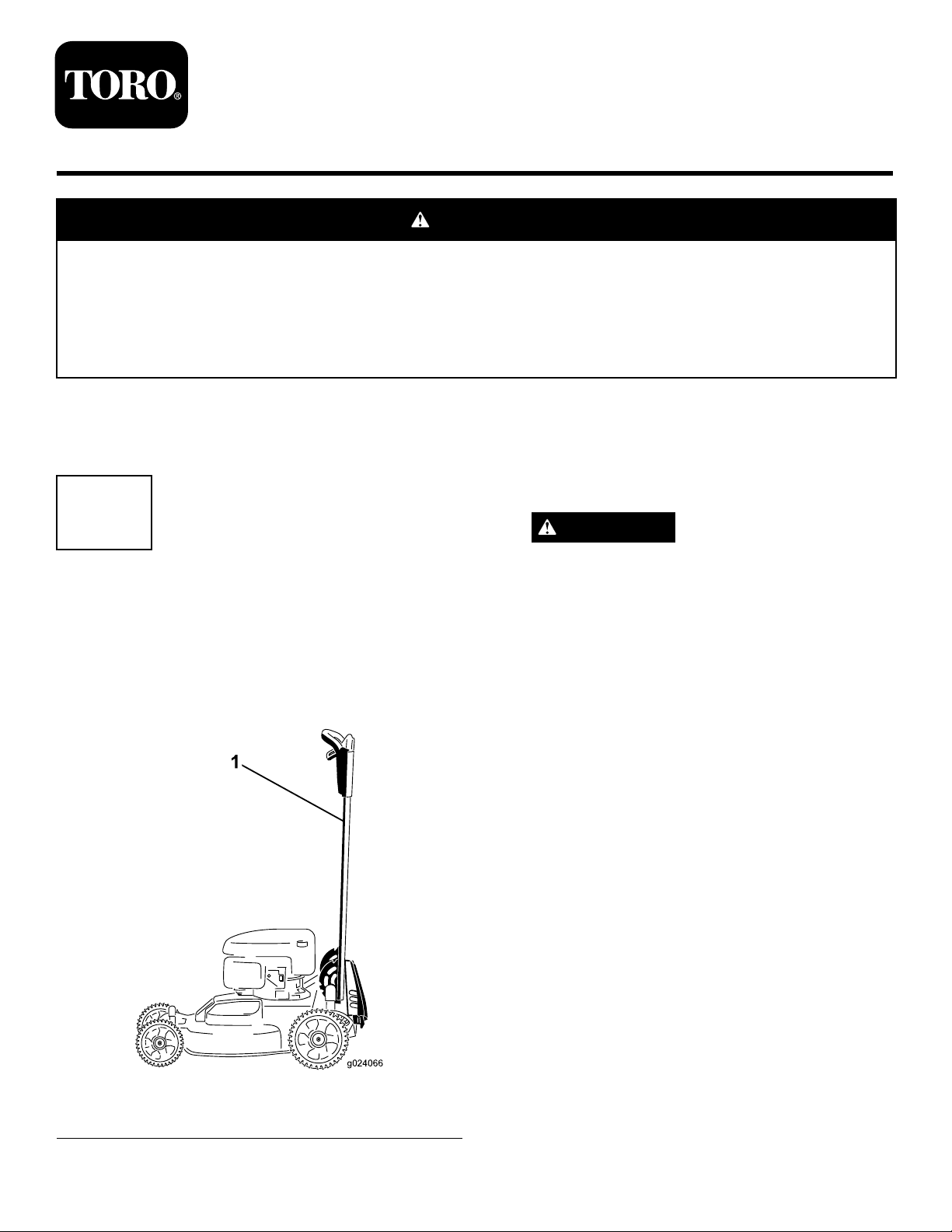
1
PreparingtheMachine
NoPartsRequired
Procedure
1.Lockthehandleintheverticalposition(Figure1);refer
toAdjustingtheHandleHeightintheOperator’sManual.
2.Disconnectthewirefromthesparkplug.
WARNING
Thebladesaresharp;contactingabladecould
resultinseriouspersonalinjury.
•Disconnectthewirefromthesparkplug.
•Weargloveswhenservicingtheblade.
3.Tipthemachineontoitsside,withthedipstickdown,
untiltheupperhandlerestsontheground.
1.Handlelockedintheverticalposition
©2013—TheToro®Company
8111LyndaleAvenueSouth
Bloomington,MN55420
Figure1
Registeratwww.T oro.com.
OriginalInstructions(EN)
PrintedintheUSA
AllRightsReserved
*3379-433*A
Page 2
2
G016530
1
2
3
4
3
RemovingtheExistingBlades
NoPartsRequired
Procedure
1.Useablockofwoodtoholdeachbladesteady,andturn
thebladeboltcounterclockwiseasshowninFigure2.
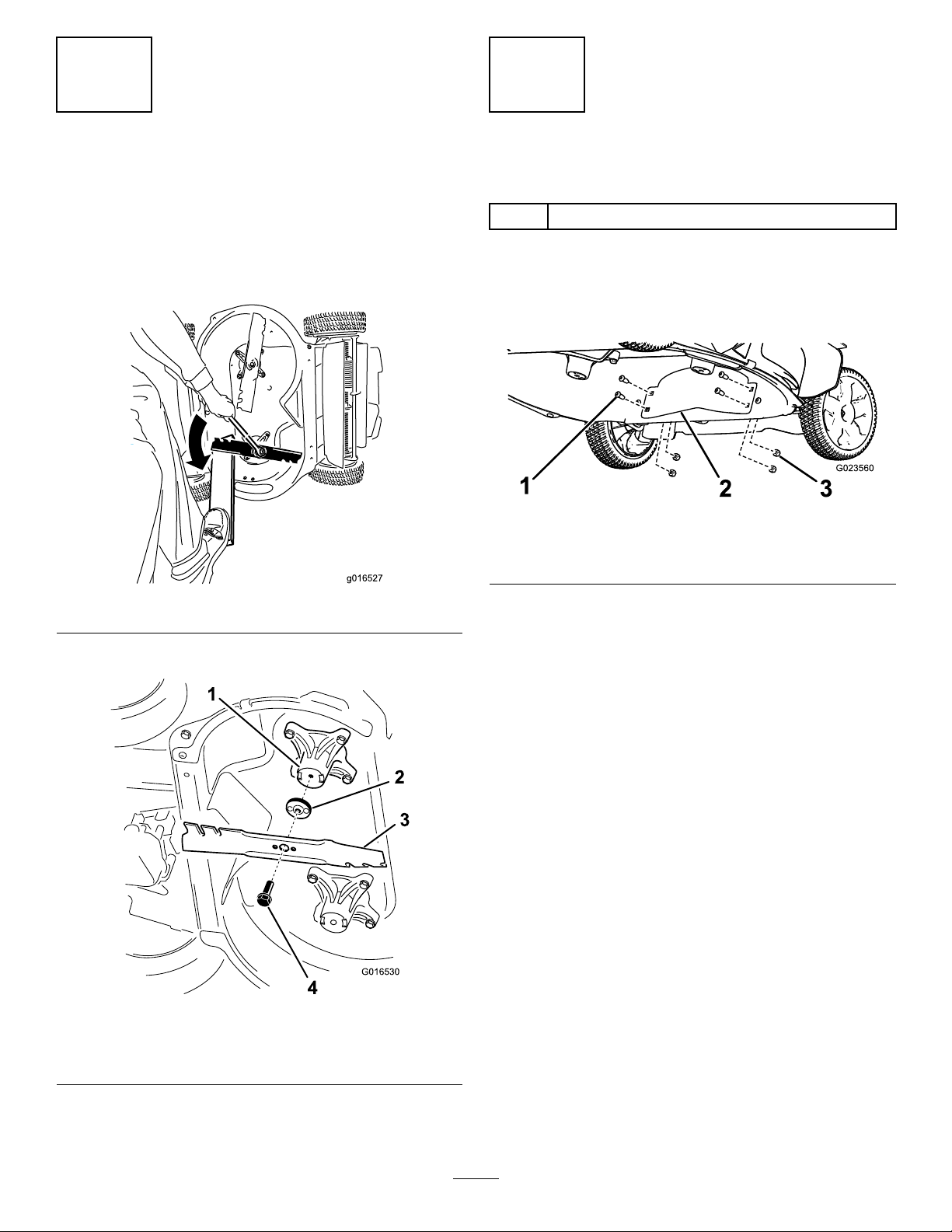
InstallingtheBafe
Partsneededforthisprocedure:
1
Bafe
Procedure
1.Removethe4boltsand4nutsinthefrontofthe
machinehousing(Figure4).
Figure4
1.Bolt(4)3.Nut(4)
2.Bafe
Figure2
2.RemoveeachbladeasshowninFigure3.
Figure3
1.Spindle(2)3.Blade(2)
2.Bladedriver(2)4.Bladebolt(2)
2.Installthebafewiththe4boltsand4nutsthatyou
removedinstep1(Figure4).
2
Page 3

g016537
4.Installtheotherbladeinthesamemannerastherst
1
G016536
blade(refertosteps1and2).
4
InstallingtheHigh-liftBlades
Partsneededforthisprocedure:
2
High-liftblade
Procedure
1.Installtherstbladesothatitishorizontal,alongwith
allmountinghardwareasshowninFigure3.
Note:Tightentheboltwithyourngers.
Important:Positionthecurvedendsoftheblades
topointtowardthemachinehousing.Nestthe
raisedareasoneachbladedriverwiththerecesses
intheheadofitscorrespondingspindle,andnest
thepinsontheothersideofeachbladedriverwith
theholesinitscorrespondingblade.
2.Steadythebladewithablockofwood,andturnthe
bladeboltclockwisewithatorquewrenchasshown
inFigure5.
Note:Thebladesshouldbeperpendicular,forming
aninverted“T”asshowninFigure6.
Figure6
1.Blade(2)
5.Tightenthesecondblade;refertostep2.
6.Rotatethebladesbyhandafull360°turntoensure
thattheydonottouch.
Note:Ifthebladestoucheachother,theyarenot
mountedcorrectly.Repeatthisprocedureuntilthe
bladesnolongertoucheachother.
Note:Torquethebladeboltto82N-m(60ft-lb).
Important:Abolttorquedto82N-m(60ft-lb)is
verytight.Putyourweightbehindthewrenchand
tightentheboltsecurely.Thisboltisverydifcult
toovertighten.
WARNING
Incorrectlyinstallingthebladescoulddamagethe
machineorcauseaninjurytotheoperatororto
bystanders.
5
ReplacingtheSide-discharge Door
Partsneededforthisprocedure:
1
Side-dischargedoor
1
Spring
Procedure
1.Removethe2hex-headbolts(3/8-inch)thatsecurethe
side-discharge-doorassemblyontothemowerhousing
(
Figure7),andremovetheside-dischargedoorfrom
themachine.
Figure5
Note:Donotdiscardtheboltsorthedoorassembly .
3.Rotatetheinstalledblade1/4turnuntilitisvertical.
3
Page 4

g024067
1
2
Figure7
G024028
1
g024068
G024031
1.Hex-headbolts
2.Side-dischargeopening
2.Prytherodoutofthespringontheside-discharge
doorwithalarge,at-headscrewdriversothatthe
otherendoftherodisbeyondtheopeningintheend
ofthedoorhinge(Figure8).
Figure9
1.Insertthelegofthespringhere.
6.Wedgetheside-discharge-doorassemblyopenwith
alargescrewdriversothatyoucaninstallthedoor
assemblyontothemowerhousing(Figure10).
Figure10
Figure8
3.Grasptheexposedendoftherodwithapliersand
removetherod.
Note:Donotdiscardtherod.
4.Removethespringandthebracketfromthe
side-dischargedoor.
Note:Donotdiscardthebracketorthe2hex-head
bolts.
5.Assemblethebracket,thenewspring,andtherodonto
thenewside-dischargedoor.
Note:Insertalegofthespringintotheopeningof
thedoorinthelocationshownin
7.Returnthemachinetotheoperatingposition.
8.Positionthedoorassemblyontothehousing,andload
thespringbysettingthefreespringlegontothemower
housing.
9.Alignthe2holesofthebracketofthedoorassembly
withthe2holesinthemowerhousing.
10.Securethedoorassemblytothemowerhousingwith
the2hex-headboltspreviouslyremoved.
Note:Tightenthehex-headboltssecurely .
11.Removethescrewdriverfromtheside-dischargedoor
andallowthedoortoclose.
12.Connectthewiretothesparkplug.
Figure9.
4
 Loading...