

Page 1
FormNo.3378-969RevA
1
G016519
High-LiftBladeandBafeKit
2013andAfterTimeMasterLawnMower
ModelNo.127-6818
InstallationInstructions
Important:Youwillneedatorquewrenchtoinstallthebladesproperly.Ifyoudonothaveatorquewrenchorare
uncomfortableperformingthisprocedure,contactanAuthorizedServiceDealer.
Note:Determinetheleftandrightsidesofthemachinefromthenormaloperatingposition.
WARNING
CALIFORNIA
Proposition65Warning
ThisproductcontainsachemicalorchemicalsknowntotheStateofCaliforniato
causecancer,birthdefects,orreproductiveharm.
1
PreparingtheMachine
NoPartsRequired
Procedure
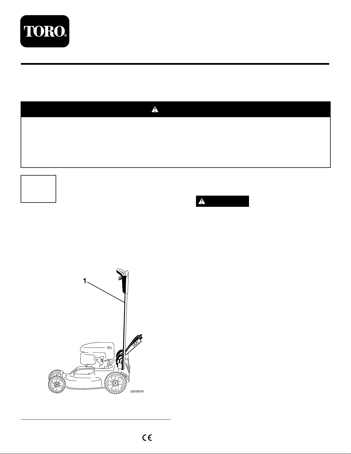
1.Lockthehandleintheverticalposition(Figure1);refer
toAdjustingtheHandleHeightintheOperator’ sManual.
2.Tipthemachineontoitsside,withthedipstickdown,
untiltheupperhandlerestsontheground.
WARNING
Thebladesaresharp;contactingabladecould
resultinseriouspersonalinjury.
•Disconnectthewirefromthesparkplug.
•Weargloveswhenservicingtheblade.
1.Handlelockedintheverticalposition
©2013—TheToro®Company
8111LyndaleAvenueSouth
Bloomington,MN55420
Figure1
Registeratwww.T oro.com.
OriginalInstructions(EN)
PrintedintheUSA
AllRightsReserved
*3378-969*A
Page 2
2
G016530
1
2
3
4
3
RemovingtheExistingBlades
NoPartsRequired
Procedure
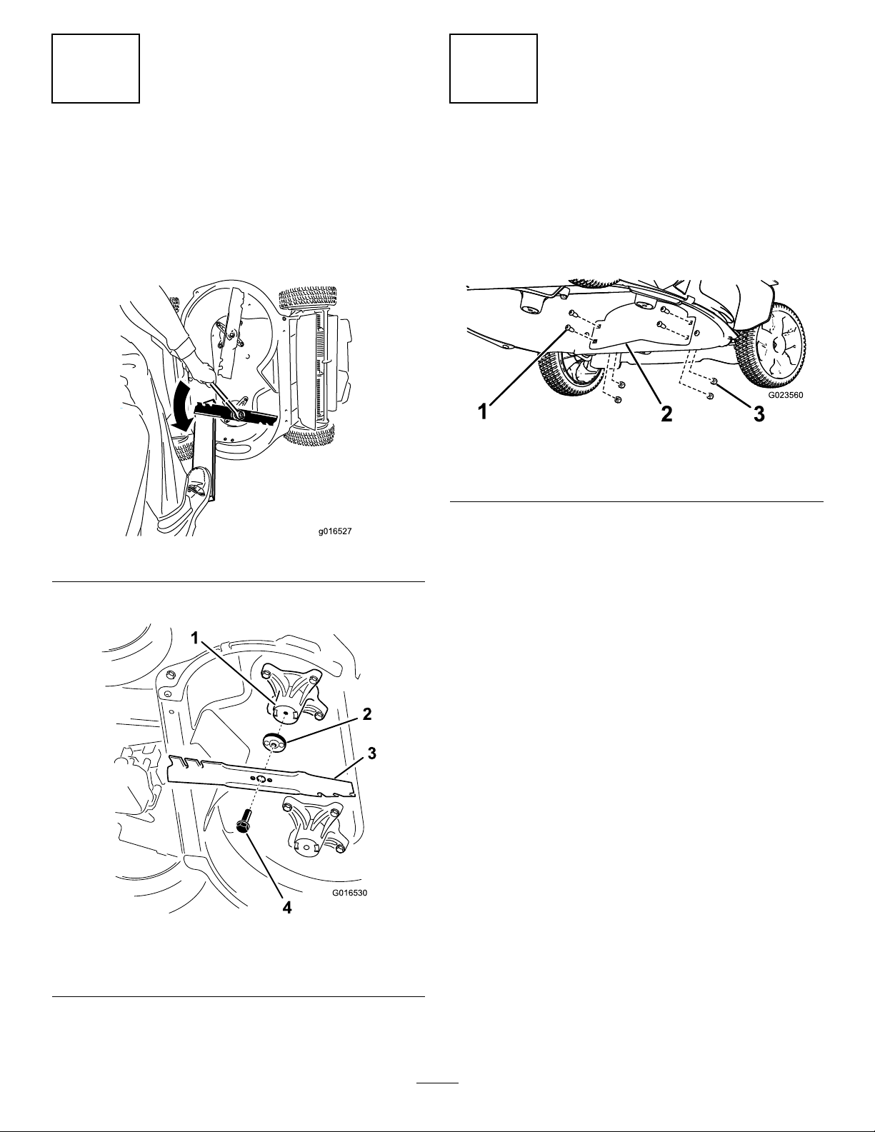
1.Useablockofwoodtoholdeachbladesteady,andturn
thebladeboltcounterclockwiseasshowninFigure2.
Figure2
InstallingtheBafe
NoPartsRequired
Procedure
1.Removethe4boltsand4nutsinthefrontofthe
machinehousing(Figure4).
Figure4
1.Bolt(4)3.Nut(4)
2.Bafe
2.Installthebafewiththe4boltsand4nutsthatyou
removedinstep1(Figure4).
2.RemoveeachbladeasshowninFigure3.
Figure3
1.Spindle(2)3.Blade(2)
2.Bladedriver(2)4.Bladebolt(2)
2
Page 3

4
g016537
g01 6536
1
InstallingtheHigh-liftBlades
NoPartsRequired
Procedure
1.Installtherstbladesothatitishorizontal,alongwith
allmountinghardwareasshowninFigure3.
Note:Tightentheboltwithyourngers.
Important:Positionthecurvedendsoftheblades
topointtowardthemachinehousing.Besureto
nesttheraisedareasoneachbladedriverwiththe
recessesintheheadofitscorrespondingspindle,
andthepinsontheothersideofeachbladedriver
withtheholesinitscorrespondingblade.
Figure6
1.Blade(2)
4.Tightenthesecondblade;refertostep2.
5.Rotatethebladesbyhandafull360°turntoensure
thattheydonottouch.
2.Steadyeachbladewithablockofwood,andturnthe
bladeboltclockwisewithatorquewrenchasshownin
Figure5;torquethebladeboltto60ft-lb(82N-m).
Important:Abolttorquedto60ft-lb(82N-m)is
verytight.Putyourweightbehindthewrenchand
tightentheboltsecurely.Thisboltisverydifcult
toovertighten.
Note:Ifthebladestoucheachother,theyarenot
mountedcorrectly.Repeatsteps1through3untilthe
bladesnolongertoucheachother.
WARNING
Incorrectlyinstallingthebladescoulddamagethe
machineorcauseaninjurytotheoperatororto
bystanders.
3.Rotatetheinstalledblade1/4turnuntilitisvertical,
andinstalltheotherbladeinthesamemannerasthe
rst(refertostep1).
Note:Thebladesshouldbeperpendicular,forming
aninverted“T”asshowninFigure6.
Figure5
3
Page 4

 Loading...