

Page 1

FormNo.3394-391RevA
CEBaggerComplianceKit
48inZMaster
ModelNo.127-0339
Note:Determinetheleftandrightsidesofthemachinefromthenormaloperatingposition.
Note:TocreateaCEbagger,installthiskitontheBlowerandDriveKitmodel78571andwiththeE-ZVac™TwinSoft
BaggerKitmodel78569.
®
2000SeriesMower
InstallationInstructions
Installation
LooseParts
Usethechartbelowtoverifythatallpartshavebeenshipped.
ProcedureDescription
1
2
3
4
5
6
7
8
Nopartsrequired
Nopartsrequired
Nopartsrequired
Nopartsrequired
Pulleyguard1
Belt-coverbracket1
Carriagebolt(1/4x1)
Hex-headbolt(3/8x1inch)
Clipnut
Shaftguard
Forwardguard1
Tensionerguard1
Lowerguard1
Hex-headbolt(1/4x3/4inch)
Washer(1/4x5/8)
Locknut(1/4inch)
Hex-headbolt(1/4x3/4inch)
Washer(5/16x3/4inch)
Washer(1/4x1/2inch)
Retainer1
Qty.
Use
–
–
–
–
1
1
1
1
2
2
2
1
1
1
Preparethemower.
Removethedischargechute.
Removethebeltcoverandbracket.
Removetheblowerkitparts.
Installthedeckbracket.
Installtheupperguards.
Installthelowerguard.
Installthebeltcover.
9
©2015—TheToro®Company
8111LyndaleAvenueSouth
Bloomington,MN55420
Supportrod
Registeratwww.T oro.com.
1Installthesupportrod.
OriginalInstructions(EN)
PrintedintheUSA
AllRightsReserved
*3394-391*A
Page 2
g015594
1
6 2
4
7
3
5
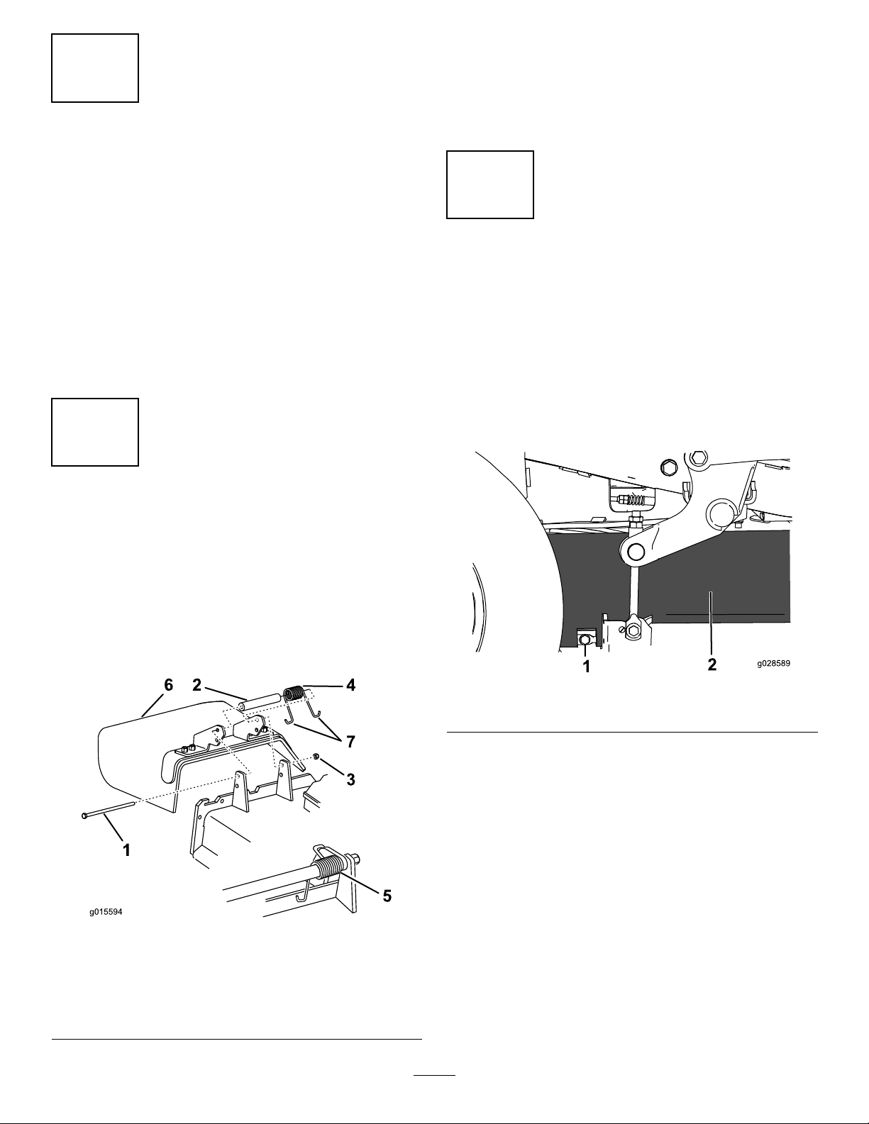
2.Removethesidedischargechutefromthemowerdeck
(Figure1).
1
PreparingtheMower
NoPartsRequired
Procedure
1.Parkthemachineonalevelsurface,settheparking
brake,andremovetheignitionkey .
2.Thoroughlycleanmowerdeck.Alldebrismustbe
removedtoensurethekitwilltproperly .
3.Repairallbentordamagedareasandreplaceany
missingparts.
4.Lowerthemowerdecktothelowestheight-of-cut
position;refertothemowerOperator’sManual.
2
RemovetheDischargeChute
Note:Retainthechuteandhardwareforinstallation
whenoperatingthemowerwiththebloweraccessory
removed.
3
RemovingtheBeltCoverand
Bracket
NoPartsRequired
RemovingtheBeltCover
Removethebeltcoverasfollows:
1.Loosenandremovethebottomboltofthemower-deck
curtaintoreleasethecurtain(Figure2).Retainthebolt.
NoPartsRequired
RemovingtheDischargeChute
Important:Installtheside-dischargechutewhenyou
removethebaggerandblower.
1.Removethelocknut,bolt,spacer,andspringthatsecure
theside-dischargechutetothemowerdeck(Figure1).
Figure1
1.Bolt
2.Spacer6.Side-dischargechute
3.Locknut
4.Spring
5.Springinstalled
7.J-hookendofspring
Figure2
1.Bolt
2.Rotatetheboltthatsecuresthebeltcovertothe
counterclockwisetoloosenit(Figure3).
2.Curtain
2
Page 3
G018856
1
2
3
4
5
Figure3
4
RemovingtheBlowerKitParts
(IfInstalled)
NoPartsRequired
RemovingtheBeltCoverfortheBlower
Iftheblowerkitisinstalledonthemachine,removethebelt
coverinstalledfrombloweranddrivekitasfollows:
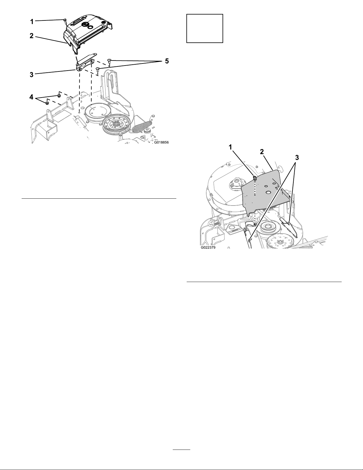
1.Removethethumbscrewthatsecuresthebeltcover
(Figure4).
1.Bolt(retainedtothebelt
cover)
2.Beltcover
3.Cover-mountingbracket
3.Removethebeltcoverandboltfromthemounting
bracket(Figure3).
Note:Retainthebeltcoverandboltforinstallationwhen
operatingthemowerwiththebloweraccessoryremoved.
RemovingtheCoverMountingBracket
1.Removethe2boltsand2angenutsthatsecurethe
covermountingbrackettothedeck(Figure3).
Note:Retainaangenutforinstallationofthe
kit;refertoInstallingthePulleyGuardandBelt-Cover
Bracket(page5).
2.Removethebracket.
Note:Retainthecovermountingbracket,bolts,and
angenutforinstallationwhenoperatingthemower
withthebloweraccessoryremoved.
4.Flangenut(3/8inch)
5.Carriagebolt(3/8x7/8
inch)
Figure4
1.Thumbscrew
2.Beltcover
2.Movethecoveroutwarduntiltheedgeofthecover
clearsthehooksinthedeckanges(Figure4).
3.Removethecoverfromthedeck.
Note:Discardthethumbscrew .
Note:Retainthebeltcoverforinstallationwith
thekit;refertoInstallingtheBeltCover(page9).
3.Deckangehooks
RemovingtheBeltCoverBracket
Iftheblowerkitisinstalledonthemachine,removethe
beltcoverbracketinstalledfromthebloweranddrivekitas
follows:
1.Removethe2carriagebolts(1/4x3/4inch)and2
locknuts(1/4inch)thatsecurethebeltcoverbracket
totheforwardangeofthemowerdeck(Figure3).
3
Note:Retain1carriageboltand2locknutsfor
installationwiththekit;refertoInstallingthePulley
GuardandBelt-CoverBracket(page5).
Page 4
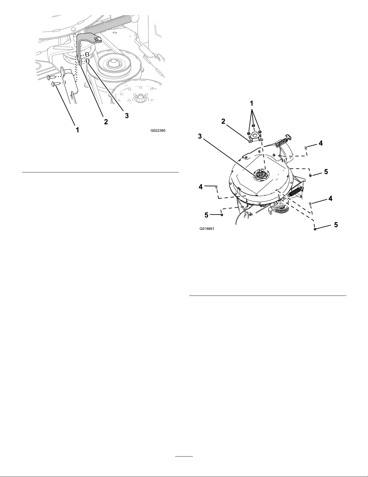
Figure5
G018861
1
2
4
5
5
4
5
4
3
RemovingtheShaftCoverand
Hardware
1.Removethe3serratednutsthatsecuretheshaftcover
totheblowerassembly(Figure6).
Note:Donotloosentheboltsandnutsthatsecurethe
upper-bearinghousingthatarebeneaththeshaftcover.
Note:Retaintheserratednutsfortheshaftguard
installation;refertoInstallingtheShaftGuard(page
6).
1.Carriagebolt(1/4x3/4
inch)
2.Beltcoverbracket
3.Locknut
2.Removethebeltcoverbracketfromthemowerdeck
(Figure3).
Note:Discardthebeltcoverbracket.
Figure6
BlowerShaftCoverandHardwareRemoval
1.Serratednut(5/16inch)4.Hex-headbolt(1/4x3/4
inch)
2.Shaftcover5.Locknut(1/4inch)
3.Boltandnut(upper
bearinghousing)
2.Removeanddiscardtheshaftcover(Figure6).
3.Removethe3hex-headbolts(1/4x3/4inch)and3
locknuts(1/4inch)fromtheblowerhousingasshown
inFigure6.
Note:Retaintheboltsandnutsfortheguard
installation;refertoInstallingtheUpperGuards
(page6).
4
Page 5

5
InstallingthePulleyGuardand
Belt-coverBracket
Partsneededforthisprocedure:
1Pulleyguard
1Belt-coverbracket
1
Carriagebolt(1/4x1)
1
Hex-headbolt(3/8x1inch)
1
Clipnut
InstallingthePulleyGuardand
Belt-CoverBracket
1.Aligntheholesofthepulleyguardtotheholeinthe
forwarddeectorbracketandtheoutboardholeinthe
forwarddeckange(Figure7).
3.Securethepulleyguardandthebeltcoverbracketto
theforwarddeckangeattheoutboardholewiththe
carriagebolt(1/4x1inch,CEkit)andthelocknut
(1/4inch,blowerkit)thatyouremovedinstep1of
RemovingtheBeltCoverBracket(page3);referto
Figure7.
4.Securethebeltcoverbrackettotheforwarddeckange
attheinboardholewiththeacarriagebolt(1/4x3/4
inch,blowerkit)andthelocknut(1/4inch,blowerkit)
thatyouremovedinstep1ofRemovingtheBeltCover
Bracket(page3);refertoFigure7.
5.Aligntheholeintherearangeofthebelt-cover
bracketwiththeholeinthedeckwhereyouremoved
thebeltcoverbracketinstep1ofRemovingtheCover
MountingBracket(page3);refertoFigure7.
6.Securetherearangeofthebelt-coverbrackettothe
deckwithahex-headbolt(3/8x1inch)andtheange
nut(3/8inch)thatyouremovedinstep1ofRemoving
theCoverMountingBracket(page3);refertoFigure7.
7.Aligntheclipnutwiththeholeinthetopofthe
belt-coverbracket,andpushtheclipnutontothe
bracket(Figure7).
Note:Thepulleybracketwrapsaroundtheoutboard
edgeofthedeectorbracket
Figure7
1.Pulleyguard
2.Locknut(1/4inch,blower
kit)
3.Belt-coverbracket
4.Hex-headbolt(3/8x1
inch,CEkit)
5.Deckhole
6.Clipnut
7.Flangenut(3/8inch)
8.Deectorbracket(forward)
9.Hex-headbolt(1/4x1
inch,CEkit)
10.Carriagebolt(1/4x3/4
inch,blowerkit)
11.Deckange(forward)
2.Alignthebelt-coverbrackettotheholesattherearside
oftheforwarddeckange(Figure7).
5
Page 6

G018858
1
2
4
5
6
6
7
4
4
3
3.Alignthetensionerguardtotheupperblowerhousing
(Figure8).
6
InstallingtheUpperGuards
Partsneededforthisprocedure:
1
Shaftguard
1Forwardguard
1Tensionerguard
InstallingtheShaftGuard
1.Aligntheshaftguardtothe3boltsand3nutsthat
securetheupper-bearinghousing(Figure8).
4.Securethetensionerguardtotheupperblowerhousing
with2hex-headbolt(1/4x3/4inch)and2locknut
(1/4inch)thatyouremovedinstep3ofRemovingthe
ShaftCoverandHardware(page4);refertoFigure8.
7
InstallingtheLowerGuard
Partsneededforthisprocedure:
1Lowerguard
2
Hex-headbolt(1/4x3/4inch)
2
Washer(1/4x5/8)
2
Locknut(1/4inch)
RemovetheBlower
Ifinstalledremovetheblowerassemblyfromthemower
deckasfollows:
1.Pullthespringloadedidlerpulleyawayfromthexed
springpost,andremovethebeltfromtheidlerpulley
(Figure9).
Figure8
5.Forwardguard
7.Tensionerguard
1.Latchpin(lockingposition)6.Belt(alignedtotheidler
2.Chutebracket
3.Blowerassembly
4.Springhookends
5.Idlerpivotbracket
Figure9
pulley)
7.Idlerspringpost
8.Spring
9.Fixedspringpost
1.Serratednut(5/16inch)
2.Shaftguard6.Locknut(1/4inch)
3.Boltandnut(upper
bearinghousing)
4.Hex-headbolt(1/4x3/4
inch)
2.Securetheshaftguardtotheblowerwiththe3serrated
nutsthatyouremovedinstep1ofRemovingtheShaft
CoverandHardware(page4);referto(Figure8).
InstallingtheUpperGuards
1.Aligntheforwardguardtotheupperblowerhousing
(Figure8).
2.Securetheforwardguardtotheupperblowerhousing
withahex-headbolt(1/4x3/4inch)andalocknut
(1/4inch)thatyouremovedinstep3ofRemovingthe
ShaftCoverandHardware(page4);refertoFigure8).
6
Page 7

2.Movetheidlerpivotbrackettowardthexedspring
G018367
1
2
3
2
4
6
5
7
7
11
9
10
5
1
2
3
4
98
6
7
10
G018859
post.removethehookofthespringfromtheidler
springpost(Figure9).
3.Routethebeltbeneaththeidlerpulley(Figure10).
DrillingtheMountingHolesforthe
LowerGuard
1.Alignthelowerguardtotheblower-chutebracketas
showninFigure11.
Figure11
Figure10
1.Drivepulley
2.Blowerbelt
3.Blowerpulley7.Mowerdeck
4.Idler/tensionpulley
5.Blower(housing
repositionedforillustrative
purposes)
6.Blowerinposition(housing
portionremovedfor
illustrativepurposes)
1.Hole1
2.Hole2
3.Hole39.Rivettails
4.Hole410.Blower-chutebracket
5.Lowerguard
6.Washer
2.Alignhole2andhole4ofthelowerguardtotherivet
tailsprotrudingthroughtheblower-chutebracket
(Figure11).
Note:Ensurethattheangeofthelowerguard(the
angewiththeholes)isatagainsttheblower-chute
bracket.
7.Hex-headbolt(1/4x3/4
inch)
8.Locknut(1/4inch)
11.Drillbit7mm(0.277inch)
3.Marktheoutlineofhole1andhole3ofthelower
4.Removethebeltfromdrivepulley(Figure10).
5.Movetheblowerlatchpintotheopenpositionand
swingthebloweroutward(Figure9).
6.Removetheblowerandbeltfromthemowerdeck.
guardontheblower-chutebracket,andremovethe
guard(Figure11).
4.Locatethemarksontheblower-chutebracket,and
center-punchthelocations.
5.Drill7mm(0.277inch)holesintheblower-chute
bracketatthe2center-punchmarks(Figure11).
7
Page 8

InstallingtheLowerGuard
G018860
1
2
3
4
5
6
7
6
8
Note:Installthelowerguardwiththeblowerassembly
removedfromthemowerdeck;refertothe48inE-ZV ac™
BlowerandDriveKitInstallationInstructions.
1.Alignthelowerguardtotheblower-chutebracket
(Figure11).
2.Alignhole2andhole4ofthelowerguardtothe
rivettailsprotrudingthroughtheblower-chute
bracket(Figure11).
3.Securethelowerguardtotheblowerwith2hex-head
bolt(1/4x3/4inch),2washers,and2locknut(1/4
inch)throughhole1andhole4oftheguard(Figure
11).
8
InstallingtheBeltCover
Partsneededforthisprocedure:
1
Hex-headbolt(1/4x3/4inch)
1
Washer(5/16x3/4inch)
1
Washer(1/4x1/2inch)
1Retainer
InstallingtheBlower
IfyouremovedtheblowerinRemovetheBlower(page6),
installtheblowerassemblytothemowerdeckasfollows:
Note:Refertothe48in,52in,and60inE-ZV ac™TwinSoft
BaggerOwner’ sManual.
1.Aligntheblowerbeltaroundthepulleyoftheblower
(Figure10).
2.Alignthepivotpinontheblowerwiththepivotpin
holeinthedeckandlowertheblowerontothedeck.
3.Opentheblowerlatchpin,closetheblowertothedeck,
andsecurethelatchpintothechutebracket(Figure9).
Note:Ensurethatthelatchpinextendsthroughthe
holeinthechutebracketandthepulleyguard.
4.Temporarilyroutethebeltbeneaththeidlerpulley
(Figure10).
5.Routethebeltaroundthedrivepulley(Figure10).
6.Movetheidler/tensionpulleytowardthexedspring
post,andinstallthespringbyaligningthespringhook
ontotheidlerspringpost(Figure9).
7.Pullthespringloadedidler/tensionpulleyawayfrom
thexedspringpost,androutethebeltaroundthe
idlerpulley(Figure10).
InstallingtheBeltCoverBolt
1.Assemblethewasher(5/16x3/4inch)tothehex-head
bolt(1/4x3/4inch)asshowninFigure12.
Figure12
1.Hex-headbolt(1/4x3/4
inch)
2.Washer(5/16x3/4inch)
3.Beltcover7.Belt-coverbracket
4.Washer(1/4x1/2inch)8.Clipnut
5.Retainer
6.Deckbracketnotch
8
Page 9

2.Inserttheboltandwasherthroughtheholeinthetop
ofthebeltcoverfromthebloweranddrivekit(Figure
12).
3.Fromthebottomofthebeltcover,assemblethe
washer(1/4x1/2inch)andretaineroverthehex-head
boltthreads(Figure12).
9
InstallingtheSupportRod
Ensurethattheboltheadandwasherarepositioned
ushwiththeuppersurfaceofthebeltcoverandthe
washerandretainerareushwiththebottomsurface
ofthecover.
InstallingtheBeltCover
1.Unlatchtheblowerandpullitoutpartially.
2.Alignthebeltcoverwiththenotchesinthedeck
anges(Figure12).
3.Alignthehex-headboltinthecoverwiththeclipnut
onthebelt-coverbracket.
4.Securethebeltcovertothecoverbracketwiththe
hex-headbolt(Figure12).
5.Opentheblowerlatchpin,closetheblowertothe
deck,andsecurethelatchpintothechutebracket.
Partsneededforthisprocedure:
1
Supportrod
Procedure
1.Slidetheexistingsupportrodoutofthemower-deck
curtain(Figure13);retaintherodforfutureuseofthe
machinewithoutthebagger.
Figure13
1.Curtain2.Supportrod
2.Insertthenewsupportrodintothecurtain(Figure14).
Figure14
1.Curtain2.Supportrod
3.Securethesupportrodandmower-deckcurtainwith
theboltyouremovedinRemovingtheBeltCover
(page2)(Figure2).
9
Page 10

Notes:
10
Page 11

Notes:
11
Page 12

 Loading...