

Page 1
FormNo.3413-588RevA
CEKit
122cmand132cmE-ZVac
ModelNo.126-9360
ModelNo.126-9361
™
BaggerforTitan
WARNING
CALIFORNIA
Proposition65Warning
ThisproductcontainsachemicalorchemicalsknowntotheStateofCaliforniato
causecancer,birthdefects,orreproductiveharm.
Note:T ocreateaCEbagger,installthiskitontheBlowerandDriveKit(T oroModelNo.78483,78486,78433,or78436
for122cmmowerdecksorToroModelNo.78484,78487,78434,or78437for132cmmowerdecks),andwiththeE-Z
Vac™TwinBaggerKit(ToroModelNo.78481or78431).
®
InstallationInstructions
HDRidingMower
Installation
LooseParts
Usethechartbelowtoverifythatallpartshavebeenshipped.
ProcedureDescription
1
2
3
4
5
6
7
Nopartsrequired
Nopartsrequired
Nopartsrequired
Left,rearsupportrod
Right,rearsupportrod1
Whiznut(3/8inch)
Nopartsrequired
CEpulleyguard
CEbelt-coverbracket
Hex-headbolt(1/4x1inch)
Carriagebolt(1/4x3/4inch)
Flangenut(1/4inch)
Hex-headbolt(3/8x1inch)
Flangenut(3/8inch)
Clipnut
Rearguard(122cmmowerdeckonly)
CEshaftguard
CEforwardguard
CEtensionerguard
Qty.
Use
–
–
–
1
4
–
1
1
1
1
2
2
2
1
1
1
1
1
Preparethemachine.
Removethedischargechute.
RemovetheOEMcoverandbracket.
Installtherearsupportrods(Bagger
Model78481only).
Removetheblowerkitparts.
InstalltheCEdeckbracket.
InstalltheupperCEguards.
©2017—TheToro®Company
8111LyndaleAvenueSouth
Bloomington,MN55420
Registeratwww.T oro.com.
OriginalInstructions(EN)
PrintedintheUSA
AllRightsReserved
*3413-588*A
Page 2

ProcedureDescription
8
9
CElowerguard
Hex-headbolt(1/4x3/4inch)
Washer(1/4x5/8)
Locknut(1/4inch)
Hex-headbolt(1/4x3/4inch)
Washer(5/16x3/4inch)
Washer(1/4x1/2inch)
Retainer1
Qty.
Use
1
2
2
2
1
1
1
InstallthelowerCEGuard.
InstalltheCEbeltcover.
2
Page 3
g015594
1
6 2
4
7
3
5
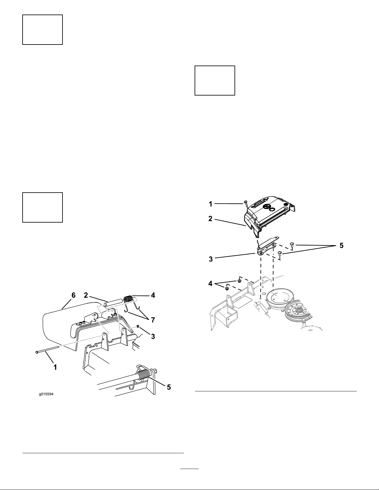
2.Removethesidedischargechutefromthemowerdeck
(Figure1).
1
PreparingtheMachine
NoPartsRequired
Procedure
1.Parkthemachineonalevelsurface.
2.Engagetheparkingbrake.
3.Shutofftheengineandremovethekey.
4.Thoroughlycleanthemowerdeck.
Note:Y oumustremoveallthedebristoensurethat
thekitwilltproperly.
5.Repairallbentordamagedareasandreplaceany
missingparts.
6.Lowerthemowerdecktothelowestheight-of-cut
position;refertothemowerOperator’sManual.
2
Note:Retainthechuteandhardwareforinstallation
whenoperatingthemowerwiththebloweraccessory
removed.
3
RemovingtheOEMCoverand
Brackets
NoPartsRequired
RemovingtheBeltCover
Ifinstalled,removetheOEMbeltcoverasfollows:
1.Rotatetheboltthatsecuresthebeltcovertothedeck
counterclockwisetoloosenit(Figure2).
RemovetheDischargeChute
NoPartsRequired
Procedure
1.Removethelocknut,bolt,spacer,andspringthatsecure
theside-dischargechutetothemowerdeck(Figure1).
Figure1
1.Bolt
2.Spacer6.Side-dischargechute
3.Locknut
4.Spring
5.Springinstalled
7.J-hookendofspring
g203155
Figure2
1.Bolt(retainedtothebelt
cover)
2.Beltcover
3.Cover-mountingbracket
g015594
2.RemovetheOEMbeltcoverandboltfromthe
mountingbracket(Figure2).
Note:RetaintheOEMbeltcoverandboltforinstallation
whenoperatingthemowerwiththebloweraccessory
removed.
4.Flangenut(3/8inch)
5.Carriagebolt(3/8x7/8
inch)
3
Page 4
RemovingtheCoverMountingBracket
1.Removethe2boltsand2angenutsthatsecurethe
covermountingbrackettothedeck(Figure2).
2.Removethebracket.
Note:RetaintheOEMcovermountingbracket,bolts,
andangenutforinstallationwhenoperatingthe
mowerwiththebloweraccessoryremoved.
4
InstallingtheRearSupport
Rods(BaggerModel78481
Only)
RemovingtheExistingLowerSupport
Rod
Removethecarriageboltandnutfromtheexistinglower
supportrodandremoveit(Figure3).
Note:Retainthecarriageboltandnut.
Figure3
1.Existinglowersupportrod
2.Nut
3.Carriagebolt
Partsneededforthisprocedure:
1
Left,rearsupportrod
1Right,rearsupportrod
4
Whiznut(3/8inch)
Procedure
1.Removetheexistingrearsupportrodsfromthe
hydrostat(Figure5).
g203724
InstallingtheNewLowerSupportRod
Installthenewlowersupportrodusingthepreviously
removedcarriageboltandnut(Figure4).
Figure4
1.Existinglowersupportrod
2.Nut
3.Carriagebolt
g203737
Figure5
LeftSideShown
1.Existingrearsupportrod2.Hydrostat
2.Installthenewleftandrightrearsupportrodsusing2
whiznuts(3/8inch)oneachside(Figure6).
g203723
4
Page 5

LeftSideShown
RemovingtheBeltCoverBracket
Iftheblowerkitisinstalledonthemachine,removethe
beltcoverbracketinstalledfromthebloweranddrivekitas
follows:
1.Removethe2carriagebolts(1/4x3/4inch)and2
locknuts(1/4inch)thatsecuresthebelt-coverbracket
totheforwardangeofthemowerdeck(Figure8).
g203736
Figure6
1.Newrearsupportrod
2.Whiznut(3/8inch)
5
RemovingtheBlowerKitParts
(IfInstalled)
NoPartsRequired
RemovingtheBeltCoverfortheBlower
Iftheblowerkitisinstalledonthemachine,removethebelt
coverinstalledfrombloweranddrivekitasfollows:
1.Removethethumbscrewthatsecuresthebeltcover
(Figure7).
Figure8
1.Carriagebolt(1/4x3/4
inch)
2.Belt-coverbracket
2.Removethebelt-coverbracketfromthemowerdeck
(Figure8).
Note:Discardthebelt-coverbracket.
3.Locknut(1/4inch)
g022380
Figure7
1.Thumbscrew2.Beltcover
2.Movethecoveroutwarduntiltheedgeofthecover
clearsthehooksinthedeckanges(Figure7).
3.Removethecoverfromthedeck.
Note:Discardthethumbscrew .
g038117
5
Page 6

RemovingtheOEMShaftCoverand
G018861
1
2
4
5
5
4
5
4
3
Hardware
RemovingtheOEMShaftCoverand
Hardware
ForStandardBlowers
1.Removethe3serratednutsthatsecuretheOEMshaft
covertotheblowerassembly(Figure9).
Note:Donotloosentheboltsandnutsthatsecure
theupper-bearinghousingthatarebeneaththeOEM
shaftcover.
ForHDBlowers
1.Removethe2nutsand2washersthatsecuretheOEM
shaftcovertotheblowerassembly(Figure10).
g018861
Figure9
BlowerShaftCoverandHardwareRemoval
1.Serratednut(5/16inch)4.Hex-headbolt(1/4x3/4
2.OEMshaftcover5.Locknut(1/4inch)
3.Boltandnut(upper
bearinghousing)
inch)
g203344
Figure10
122cmMowerDeckShown
2.RemoveanddiscardtheOEMshaftcover(Figure9).
3.Removethe3hex-headbolts(1/4x3/4inch)and3
1.Nut
2.Washer4.Bolt
3.OEMshaftcover
locknut(1/4inch)fromtheblowerhousingasshown
inFigure9.
2.RemoveanddiscardtheOEMshaftcover(Figure10).
6
Page 7

6
InstallingtheCEPulleyGuard
andBelt-CoverBracket
Partsneededforthisprocedure:
1
CEpulleyguard
1
CEbelt-coverbracket
1
Hex-headbolt(1/4x1inch)
1
Carriagebolt(1/4x3/4inch)
2
Flangenut(1/4inch)
2
Hex-headbolt(3/8x1inch)
2
Flangenut(3/8inch)
1
Clipnut
1
Rearguard(122cmmowerdeckonly)
InstallingtheCEPulleyGuardand
Belt-CoverBracket
Figure11
1.Hex-headbolt(3/8x1
inch)
2.Flangenut(3/8inch)7.Deckange(forward)
3.Rearguard(122cm
mowerdeckonly)
4.Belt-coverbracket
5.Clipnut10.CEpulleyguard
6.Flangenut(1/4inch)
8.Carriagebolt(1/4x3/4
inch)
9.Flange-headbolt(1/4x1
inch)
g203671
For122cmMowerDecks
1.AligntheholesoftheCEpulleyguardtotheholein
theforwarddeectorbracketandtheoutboardholein
theforwarddeckange(Figure11).
Note:TheCEpulleybracketwrapsaroundthe
outboardedgeofthedeectorbracket
2.AligntheCEbelt-coverbrackettotheholesattherear
sideoftheforwarddeckange(Figure11).
3.SecuretheCEpulleyguardandthebeltcoverbracket
totheforwarddeckangeattheoutboardholewith
thehex-headbolt(1/4x1inch)andaangenut(1/4
inch)asshowninFigure11.
4.Securethebelt-coverbrackettotheforwarddeckange
attheinboardholewiththeacarriagebolt(1/4x3/4
inch)andaangenut(1/4inch)asshowninFigure11.
5.AligntheholeintherearangeoftheCEbelt-cover
bracketwiththeholeinthedeckwhereyouremoved
theOEMbeltcoverbracketinstep1ofRemovingthe
CoverMountingBracket(page4);refertoFigure11.
6.SecuretherearangeoftheCEbelt-coverbracket
tothedeckwithahex-headbolt(3/8x1inch)anda
angenut(3/8inch)asshowninFigure11.
7.AligntheclipnutwiththeholeinthetopoftheCE
belt-coverbracket,andpushtheclipnutontothe
bracket(Figure11).
8.Looselyinstalltherearguardtothemowerdeckusing
ahex-headbolt(3/8x1inch)andaangenut(3/8
inch)asshowninFigure11.
Tightenthefastenersafteryouinstalltheblower;refer
toInstallingtheBlower(page11).
Important:Thisstepappliesto122cmmower
decksonly.
7
Page 8
InstallingtheCEPulleyGuardand
G018858
1
2
4
5
6
6
7
4
4
3
Belt-CoverBracket
For132cmMowerDecks
1.AligntheholesoftheCEpulleyguardtotheholein
theforwarddeectorbracketandtheoutboardholein
theforwarddeckange(Figure12).
Note:TheCEpulleybracketwrapsaroundthe
outboardedgeofthedeectorbracket
Figure12
7
InstallingtheCEUpperGuards
Partsneededforthisprocedure:
1
CEshaftguard
1
CEforwardguard
1
CEtensionerguard
InstallingtheCEShaftGuard
ForStandardBlowers
1.AligntheCEshaftguardtothe3boltsand3nutsthat
securetheupperbearinghousing(Figure13).
g203771
1.CEpulleyguard4.Flangenut(1/4inch)
2.Flange-headbolt(1/4x1
inch)
3.Carriagebolt(1/4x3/4
inch)
2.AligntheCEbelt-coverbrackettotheholesattherear
sideoftheforwarddeckange(Figure12).
3.SecuretheCEpulleyguardandthebeltcoverbracket
totheforwarddeckangeattheoutboardholewith
thehex-headbolt(1/4x1inch)andaangenut(1/4
inch)asshowninFigure12.
4.Securethebelt-coverbrackettotheforwarddeckange
attheinboardholewiththeacarriagebolt(1/4x3/4
inch)andaangenut(1/4inch)asshowninFigure12.
5.AligntheclipnutwiththeholeinthetopoftheCE
belt-coverbracket,andpushtheclipnutontothe
bracket(Figure12).
5.Clipnut
6.Belt-coverbracket
g018858
Figure13
1.Serratednut(5/16inch)5.CEforwardguard
2.CEshaftguard6.Locknut(1/4inch)
3.Boltandnut(upper
bearinghousing)
4.Hex-headbolt(1/4x3/4
inch)
2.SecuretheCEshaftguardtotheblowerwiththe3
serratednuts(Figure13).
7.CEtensionerguard
8
Page 9

InstallingtheCEShaftGuard
ForHDBlowers
InstalltheCEshaftguardtotheblowerassemblyusing2
nutsand2washers(Figure14).
8
InstallingtheCELowerGuard
Partsneededforthisprocedure:
1
CElowerguard
2
Hex-headbolt(1/4x3/4inch)
2
Washer(1/4x5/8)
2
Locknut(1/4inch)
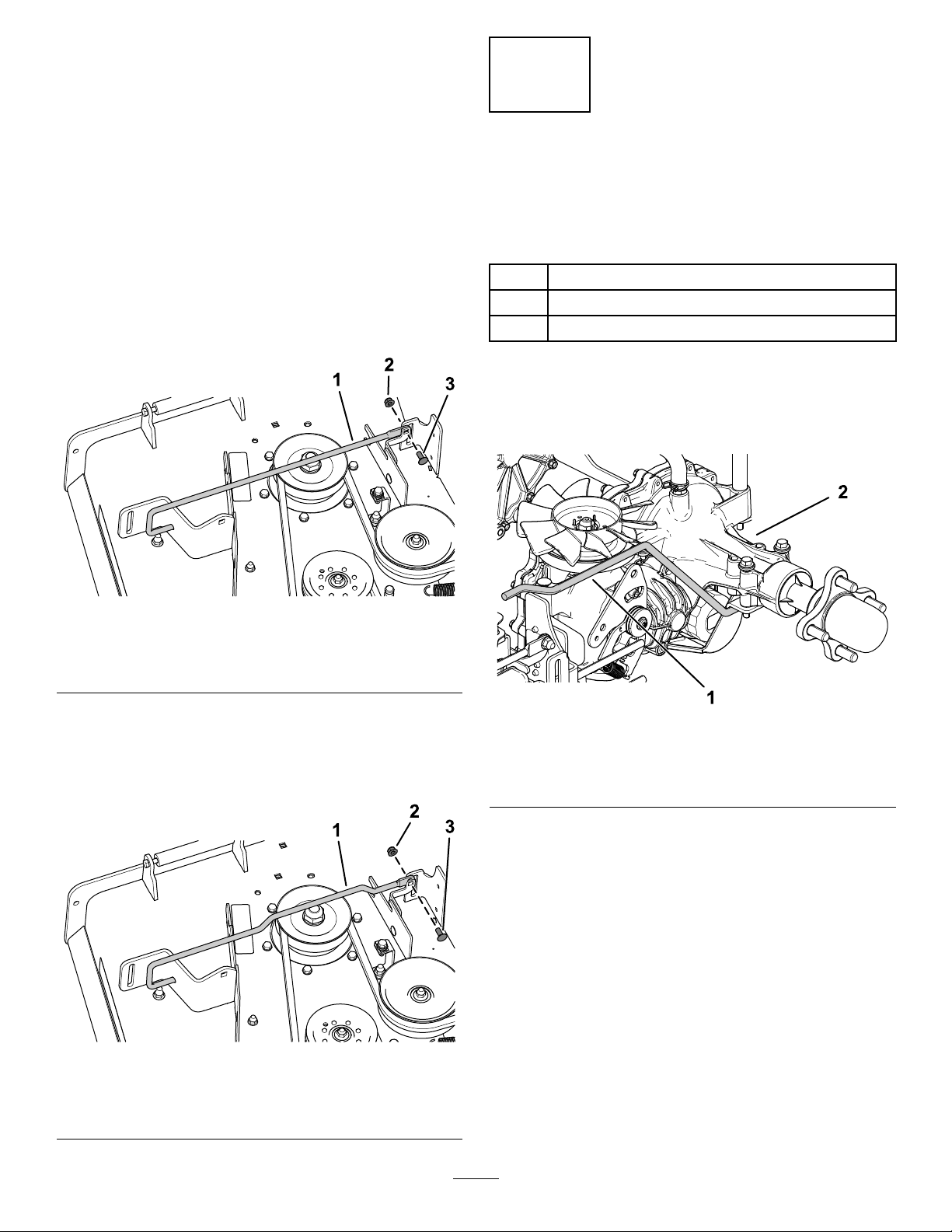
RemovingtheBlower
Ifinstalledremovetheblowerassemblyfromthemower
deckasfollows:
1.Pullthespringloadedidlerpulleyawayfromthexed
springpost,andremovethebeltfromtheidlerpulley
(Figure15).
Figure14
1.Nut
2.Washer4.Bolt
3.CEshaftguard(HD)
InstallingtheCEUpperGuards
1.AligntheCEforwardguardtotheupperblower
housing(Figure13).
2.SecuretheCEforwardguardtotheupperblower
housingwithahex-headbolt(1/4x3/4inch)anda
locknut(1/4inch)asshowninFigure13.
3.AligntheCEtensionerguardtotheupperblower
housing(Figure13).
4.SecuretheCEtensionerguardtotheupperblower
housingwith2hex-headbolt(1/4x3/4inch)and2
locknut(1/4inch)asshowninFigure13.
g203156
g203195
Figure15
1.Latchpin(lockingposition)6.Belt(alignedtotheidler
2.Chutebracket
3.Blowerassembly
4.Springhookends
5.Idlerpivotbracket
pulley)
7.Idlerspringpost
8.Spring
9.Fixedspringpost
9
Page 10

2.Movetheidlerpivotbrackettowardthexedspring
G018367
1
2
3
2
4
6
5
7
7
11
9
10
5
1
2
3
4
98
6
7
10
G018859
post.removethehookofthespringfromtheidler
springpost(Figure15).
3.Routethebeltbeneaththeidlerpulley(Figure16).
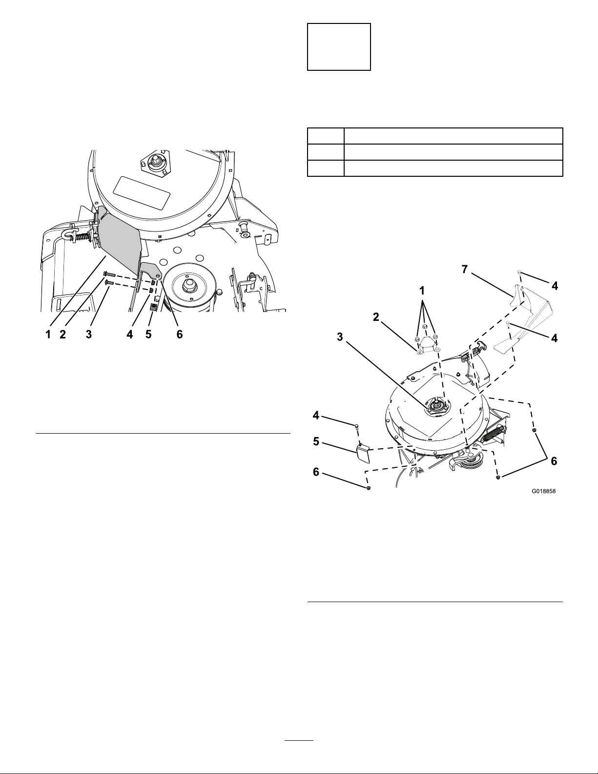
DrillingtheMountingHolesfortheCE
LowerGuard
1.AlignthelowerCElowerguardtotheblower-chute
bracketasshowninFigure17.
g018859
Figure17
Figure16
1.Drivepulley
2.Blowerbelt
3.Blowerpulley7.Mowerdeck
4.Idler/tensionpulley
5.Blower(housing
repositionedforillustrative
purposes)
6.Blowerinposition(housing
portionremovedfor
illustrativepurposes)
1.Hole1
2.Hole2
3.Hole39.Rivettails
4.Hole410.Blower-chutebracket
5.CElowerguard11.Drillbit7mm(0.277inch)
g018367
6.Washer
2.Alignhole2andhole4ofthelowerCElowerguard
totherivettailsprotrudingthroughtheblower-chute
bracket(Figure17).
Note:EnsurethattheangeoftheCElower
guard(theangewiththeholes)isatagainstthe
blower-chutebracket.
7.Hex-headbolt(1/4x3/4
inch)
8.Locknut(1/4inch)
3.Marktheoutlineofhole1andhole3oftheCElower
4.Removethebeltfromdrivepulley(Figure16).
5.Movetheblowerlatchpintotheopenpositionand
swingthebloweroutward(Figure15).
6.Removetheblowerandbeltfromthemowerdeck.
guardontheblower-chutebracket,andremovetheCE
guard(Figure17).
4.Locatethemarksontheblower-chutebracket,and
center-punchthelocations.
5.Drill7mm(0.277inch)holesintheblower-chute
bracketatthe2center-punchmarks(Figure17).
10
Page 11

InstallingtheCELowerGuard
Note:InstalltheCElowerguardwiththeblowerassembly
removedfromthemowerdeck;refertotheE-ZV ac™Blower
andDriveKitInstallationInstructions.
1.AligntheCElowerguardtotheblower-chutebracket
(Figure17).
2.Alignhole2andhole4oftheCElowerguardto
therivettailsprotrudingthroughtheblower-chute
bracket(Figure17).
3.SecuretheCElowerguardtotheblowerwith2
hex-headbolts(1/4x3/4inch),2washers,and2
locknut(1/4inch)throughhole1andhole4ofthe
CEguard(Figure17).
InstallingtheBlower
Ifyouremovedtheblower,installtheblowerassemblyto
themowerdeckasfollows:
Note:Refertothe48inor52inE-ZV ac™TwinSoftBagger
Owner’sManual.
1.Aligntheblowerbeltaroundthepulleyoftheblower
(Figure16).
2.Alignthepivotpinontheblowerwiththepivotpin
holeinthedeckandlowertheblowerontodeck.
3.Opentheblowerlatchpin,closetheblowertothe
deck,andsecurethelatchpintothechutebracket
(Figure15).
Note:Ensurethatthelatchpinextendsthroughthe
holeinchutebracketandtheCEpulleyguard.
4.Temporarilyroutethebeltbeneaththeidlerpulley
(Figure16).
5.Routethebeltaroundthedrivepulley(Figure16).
6.Movetheidler/tensionpulleytowardthexedspring
post,andinstallthespringbyaligningthespringhook
ontotheidlerspringpost(Figure15).
7.Pullthespringloadedidler/tensionpulleyawayfrom
thexedspringpost,androutethebeltaroundthe
idlerpulley(Figure16).
11
Page 12

9
InstallingtheCEBeltCover
2.Inserttheboltandwasherthroughtheholeinthetop
ofthebeltcoverfromtheOEMbloweranddrivekit
(Figure18).
3.Fromthebottomofthebeltcover,assemblethe
washer(1/4x1/2inch)andretaineroverthehex-head
boltthreads(Figure18).
Partsneededforthisprocedure:
1
Hex-headbolt(1/4x3/4inch)
1
Washer(5/16x3/4inch)
1
Washer(1/4x1/2inch)
1Retainer
InstallingtheCEBeltCoverBolt
1.Assemblethewasher(5/16x3/4inch)tothehex-head
bolt(1/4x3/4inch)asshowninFigure18.
Ensurethattheboltheadandwasherarepositioned
ushwiththeuppersurfaceofthebeltcoverandthe
washerandretainerareushwiththebottomsurface
ofthecover.
InstallingtheBeltCover
1.Unlatchtheblowerandpullitoutpartially.
2.Alignthebeltcoverwithnotchesinthedeckanges
(Figure18).
3.Alignthehex-headboltinthecoverwiththeclipnut
onthebelt-coverbracket.
4.Securethebeltcovertothecoverbracketwiththe
hex-headbolt(Figure18).
5.Opentheblowerlatchpin,closetheblowertothe
deck,andsecurethelatchpintothechutebracket.
Figure18
122cmMowerDeckShown
1.Hex-headbolt(1/4x3/4
inch)
2.Washer(5/16x3/4inch)
3.Beltcover
4.Washer(1/4x1/2inch)8.Clipnut
5.Retainer
6.Deckbracketnotch
7.CEbelt-coverbracket
g203194
12
 Loading...