

Page 1

MetalPlateKit
ZMaster
ModelNo.125-4790
®
FormNo.3378-515RevA
Commercial2000SeriesRidingMower
InstallationInstructions
Note:Keepthemowerdeckbeltinstalledduringthe
installationofthiskit.Thereisnointerferencewiththe
mowerdeckbelt.
LooseParts
Usethechartbelowtoverifythatallpartshavebeenshipped.
Description
Nopartsrequired
Nopartsrequired
Nopartsrequired
Nopartsrequired
Plate1
Starwasher
Thinatwasher
Flangenut(3/8inch)
Thickatwasher
Qty.
WARNING
CALIFORNIA
Proposition65Warning
Thisproductcontainsachemicalorchemicals
knowntotheStateofCaliforniatocausecancer,
birthdefects,orreproductiveharm.
Use
–
–
–
–
1
1
2
1
Checkthefueltank.
Installthefueltank.
Removethepulleys.
Inspecttheidler-armpulley .
Installtheplate.
CAUTION
Ifthemachinehasbeenrunning,themuferand
exhaustsystemwillbeveryhotandcancause
seriousburnsifyoutouchthem.
Allowthemachinetocoolcompletelybefore
performingthisprocedure.
CheckingtheFuelTank
Note:Ensureanewfueltankandidlerpulleyareorderedif
thereisanywearontheexistingfueltank.
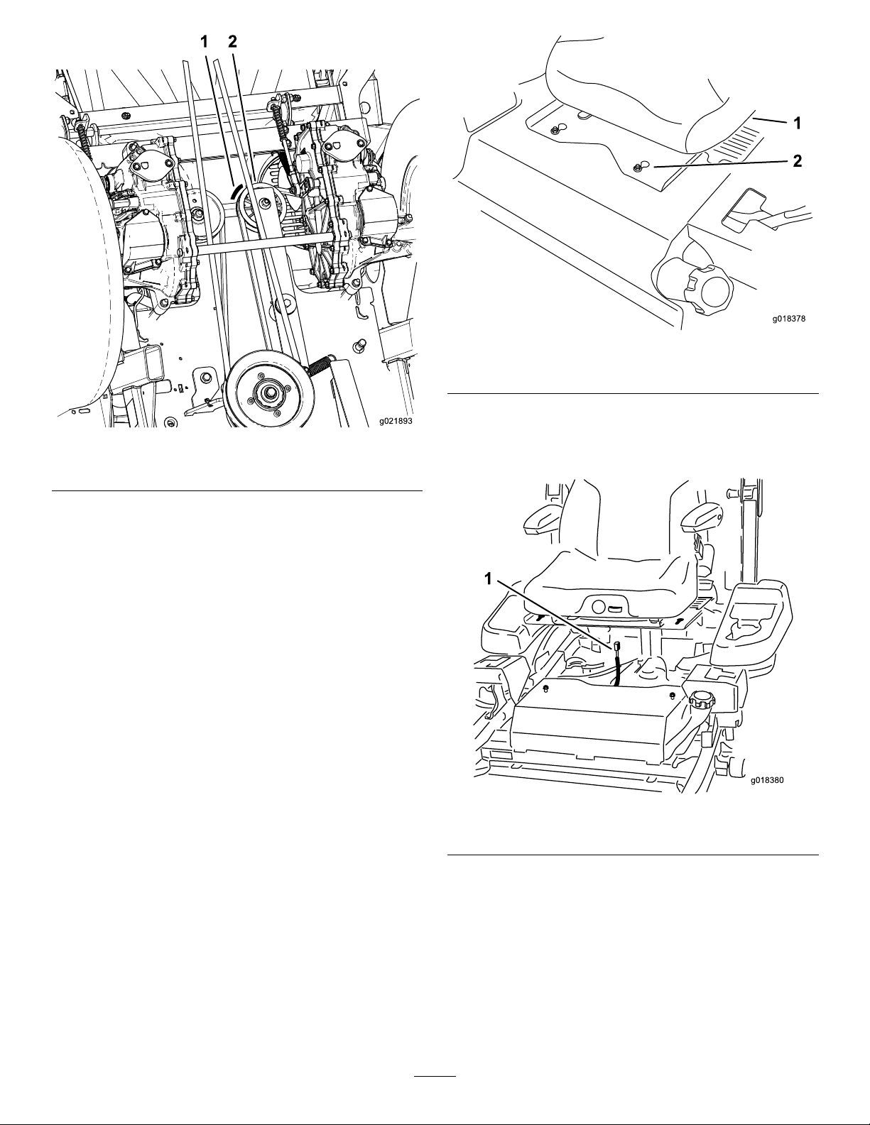
Checkthefueltankforanywearundertheidlerpulley(Figure
1).
•Ifyouseeorfeelwithyourngernail,agrooveinthefuel
tankfromtheidlerpulley,replacethefueltankandidler
©2013—TheT oro®Company
8111LyndaleAvenueSouth
Bloomington,MN55420
Registeratwww.T oro.com.
pulley(Figure1).Orderanewfueltankandanewidler
pulley.ProceedtoReplacingtheFuelTank(page2).
•Ifthefueltankdoesnothaveanywearfromtheidler
pulley,proceedtoRemovingthePulleys(page4).
OriginalInstructions(EN)
PrintedintheUSA.
AllRightsReserved
*3378-515*A
Page 2
g021893
1 2
g018378
1
2
Figure2
g018380
1
Figure1
1.Wearareaonfueltank
2.Idlerpulley
ReplacingtheFuelTank
Note:Onlyreplacethefueltankwhenthereiswearonthe
existingfueltankfromtheidlerpulley.
1.Drivethemachinetoalevelsurface.
2.DisengagethePTO ,movethemotioncontrolleversto
theneutrallockedposition,andsettheparkingbrake.
3.Stoptheengine,removethekey,andwaitforallmoving
partstostopbeforeleavingtheoperatingposition.
4.Movetheseatthefurthestrearpositiontoexposethe
frontnuts.
5.Loosenthefrontnuts.Thenutsdonotneedtobe
removed.
1.Seat
2.Frontnutswithkeyhole
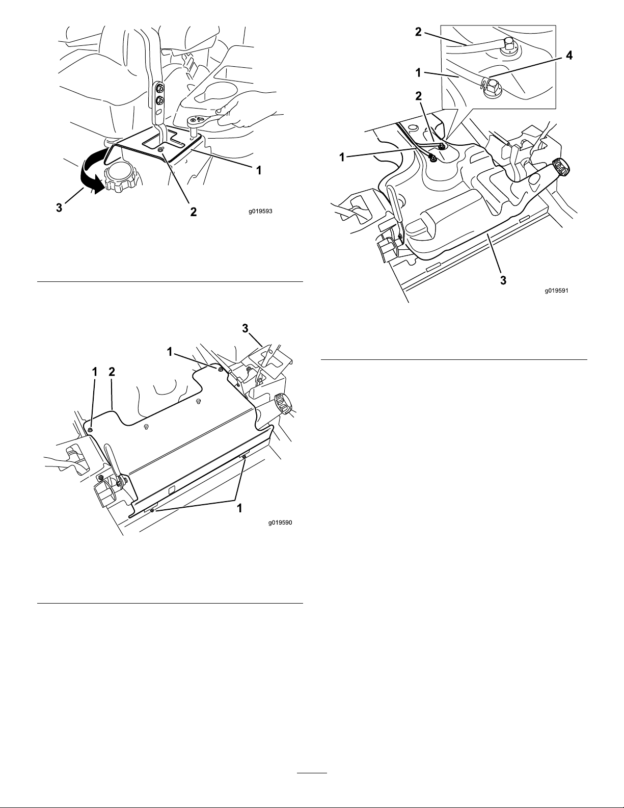
9.Removetheseatandbasefromthemachine.
10.Unplugtheharnessconnectorfromtheseatswitch
locatedundertheseat(Figure3).
6.Movetheseatthefurthestforwardpositiontoexpose
therearnuts.
1.Harnessconnector
Figure3
7.Loosentherearnuts.Thenutsdonotneedtobe
removed.
8.Slidetheseatandseatplateforwardtoallowthefront
nutstogothroughthekeyhole(
Figure2).
11.Removethetwoboltsholdingtheleftsidemotion
controlleverbracket.
12.Rotatethemotioncontrolleverbrackettoallowthe
frontpaneltoberemoved(
Figure4).
2
Page 3
g019593
3
1
2
Figure4
g019590
1 2
1
3
1
2
g019591
1
3
4
2
1
1.Motioncontrollever
bracket
2.Removethetwobolts
3.Rotatethemotioncontrol
leverbracket
13.Removethefourboltsholdingthefrontpanelinplace
andremovethefrontpanel(Figure5).
1.Fuelhose3.Fueltank
2.Venthose4.Hoseclamp
Figure6
16.Removeanyfuelfromthetankbypumpingitoutinto
afuelcan.
17.Removethetankfromthemachine.
18.Installthenewfueltankbyreversingsteps4through
17.
19.Destroytheoldfueltankbyoneofthefollowing
processes:
•Drilla1/4inchholeinthebottomofthefueltank
Figure7).
(
•Cutthellerneckoffofthefueltank(Figure7).
1.Removethesebolts3.Motioncontrollever
2.Frontpanel
14.Usingapliers,loosenthefuelhoseclampandslideit
downthefuelhose.
15.Removethefuelventhoseandfuelhosefromthefuel
tank(
Figure6).
Figure5
bracket
3
Page 4

g019797
1
2
Figure7
g021894
1
2
3
1.Cutthellerneckoff2.Drilla1/4inchhole
RemovingthePulleys
Figure8
1.Idler-springpost
2.Spring
3.Clutchpulley
6.Removetheidlerarmbolt,washer,rubberwashers,
innerspacer,idlerarm,largespacerandtheangenut
abovetheenginedeck(Figure12andFigure13).
WARNING
Mechanicalorhydraulicjacksmayfailtosupport
machineandcauseaseriousinjury.
Usejackstandswhensupportingmachine.
1.Drivethemachinetoalevelsurface.
2.DisengagethePTO ,movethemotioncontrolleversto
theneutrallockedposition,andsettheparkingbrake.
3.Stoptheengine,removethekey,andwaitforallmoving
partstostopbeforeleavingtheoperatingposition.
4.Raisetherearofmachineupandsupportitwithjack
stands.
5.Removethespringfromtheidler-springpost(
8).Thiswillreleasethetensiononthehydraulic-pump
belt.
Note:Donotremovethehydraulic-pumpbeltfrom
themachine;allowthehydraulic-pumpbelttolayloose
inthemachinewhileinstallingthiskit.
Figure
7.Removethexedidlerpulleyandwasherfromthe
machine(Figure11).Discardthewasher.
Note:Donotremovethexed-idlercarriagebolt.
4
Page 5

InspectingtheIdler-ArmPulley
1
2
3
4
g021906
5 6 7
8
g021896
1
2
InstallingthePlate
1.Inspecttheidler-armpulleytoensureitfreelyrotates
andhasnowobble.Replacethepulleyifnecessary.
2.Iftheidler-armpulleydoesnotneedtobereplaced,
torquetheidler-pulleyboltbetween27and33ft-lbs.
3.Ifthepulleyneedstobereplaced,removethepulley
fromtheidlerarm(Figure9).Makenoteofhowitis
installed.
4.Installthenewidler-armpulleywithanewangenut
(3/8inch)asshowninFigure9.
Note:Ensurethebushingisinstalledtowardsthe
idlerarm(Figure9).
5.Torquetheidler-pulleyboltbetween27and33ft-lbs.
1.Installthethinatwasherandstarwasherontothe
xed-idlercarriagebolt(Figure10).
Figure10
1.Thinatwasher2.Starwasher
2.Positiontheplateintothemachine,ushagainstthe
bottomoftheenginedeck(Figure11).
3.Installthenewthickatwasher,xed-idlerpulley
(correctorientation)andthenewlocknut(Figure11).
Note:Ensurethatthebushingisinstalledtowards
theplate(Figure11).
1.Idler-pulleybolt
2.Idler-armpulley
3.Spacer
4.Idlerarm
Figure9
5.Newangenut(3/8inch)
6.Bottomoftheidlerarm
pulley
7.Ensurethebushingis
installedtowardstheidler
arm
8.Topoftheidlerarmpulley
5
Page 6

g021897
1
2
3
4
8
5
6 7
Figure11
g021903
1
2
3
4
2
5
6
7
1.Plate
2.Newthickwasher6.Ensurethebushingis
3.Fixed-idlerpulley
4.Newangenut(3/8inch)8.Carriageboltwithat
5.Bottomofthexed-idler
pulley
installedtowardstheplate
7.Topofthexed-idler
pulley,installtowardsthe
plate
washerandstarwasher
4.Installthelargespacer,rubberwashers,idlerarm,inner
spacer,andwashertotheenginedeckwiththeidler
armboltandnewlocknut(Figure12andFigure13).
Note:Thisrequirestwopeopletocomplete;the
angenutislocatedontopoftheenginedeckandin
frontoftheengine(Figure13).
Figure12
1.Largespacer5.Washer
2.Rubberwasher6.Idler-armpivotbolt
3.Idlerarm7.Plateinstalled
4.Innerspacer
6
Page 7

g021877
1
2
3
Topviewofthemachine
g021895
1
6
2
3
4
5
9.Raisetherearofmachineup,removethejackstands,
andlowerthemachine.
Figure13
1.Engine
2.Rollbar
3.Newangenut(3/8inch)
5.Torquethenewangenutandcarriageboltatthe
xed-idlerpulleybetween27and33ft-lbs(Figure11).
6.Torquetheidler-armpivotboltbetween27and33
ft-lbs(Figure12).
7.Routethebeltaroundthepulleys(Figure14).
Note:Ensurethatthebeltisroutedaroundallpulleys.
Figure14
1.Idlerpulley4.Pumpdrivebelt
2.Idlerspringpost5.Right-handhydraulic
3.Enginepulley
8.Attachthespringtotheidler-springpost(Figure8).
pumppulley
6.Left-handhydraulicpump
pulley
7
Page 8

 Loading...