

Page 1
DeluxeSeatKit
g018378
1
2
ZMaster
ModelNo.121-7595
ModelNo.78550
®
RidingMower
Installation
LooseParts
Usethechartbelowtoverifythatallpartshavebeenshipped.
FormNo.3376-909RevB
InstallationInstructions
ProcedureDescription
1
2
3
Note:Forperformanceandsafety,2000Seriesmachines
with48inchmowerdecksrequireaweightkit(No.121-7576)
afterthedeluxeseatkitisinstalled.Obtainthecorrectweight
kitfromanAuthorizedServiceDealer.
Nopartsrequired
Seat
Spacer
Flangenut(5/16inch)
Plasticcabletie4
Nopartsrequired
1
RemovingtheSeat
NoPartsRequired
Qty.
–
1
4
4
–
7.Unplugtheharnessconnectorfromtheseatswitch
locatedundertheseat.
Removetheseat.
Installtheseat.
Testthesafetyinterlocksystem.
Use
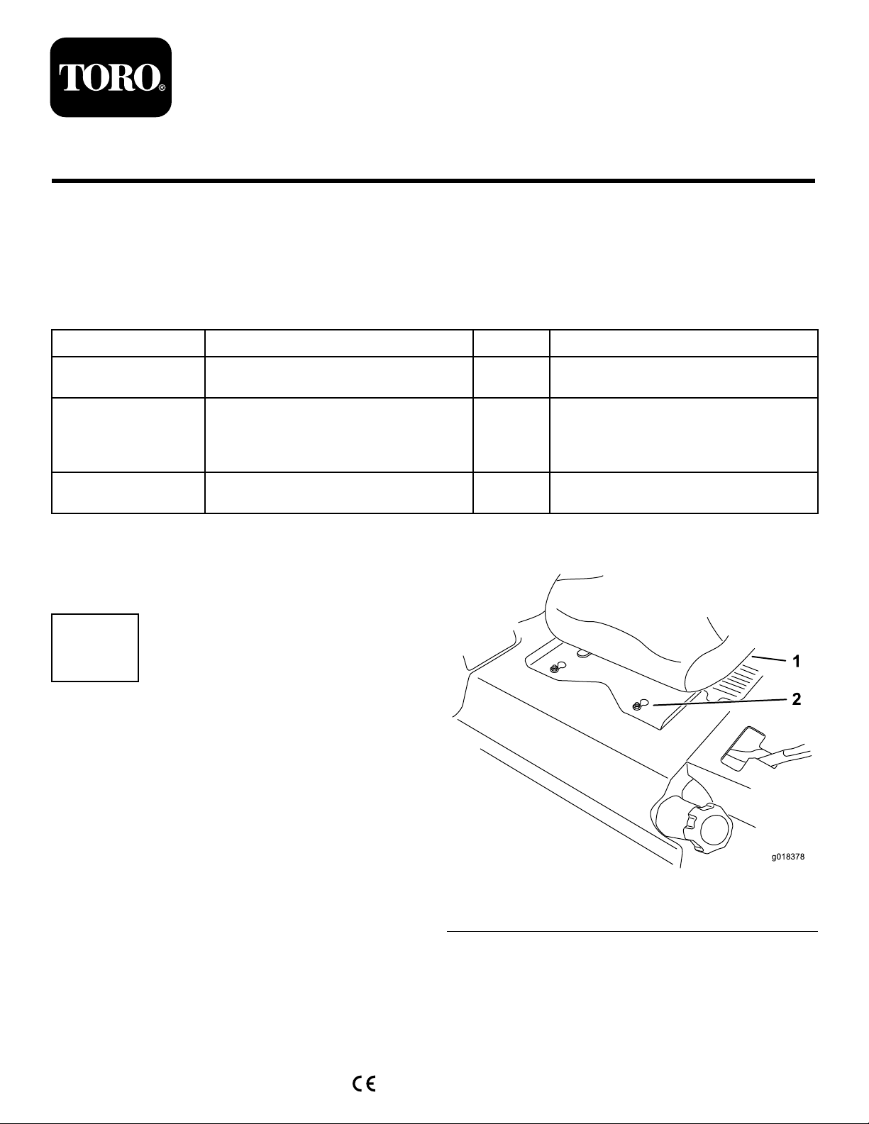
Removinga2000SeriesZMaster
MowerSeat
1.Toexposethefrontnuts,movetheseattothefurthest
rearposition.
2.Loosenthefrontnuts.Thenutsdonotneedtobe
removed.
3.Toexposetherearnuts,movetheseattothefurthest
forwardposition.
4.Loosentherearnuts.Thenutsdonotneedtobe
removed.
5.Slidetheseatandseatplateforwardtoallowthefront
nutstogothroughthekeyholes(
6.Removetheseatandbasefromthemachine.
©2013—TheT oro®Company
8111LyndaleAvenueSouth
Bloomington,MN55420
Figure1).
Registeratwww.T oro.com.
Figure1
1.Existingseat2.Frontnutswithkeyhole
OriginalInstructions(EN)
PrintedintheUSA.
AllRightsReserved
*3376-909*B
Page 2
Removinga5000or6000SeriesZ
MasterMowerSeat(TiltingSeat)
1.Unlatchtheseatandtiptheseatforward.
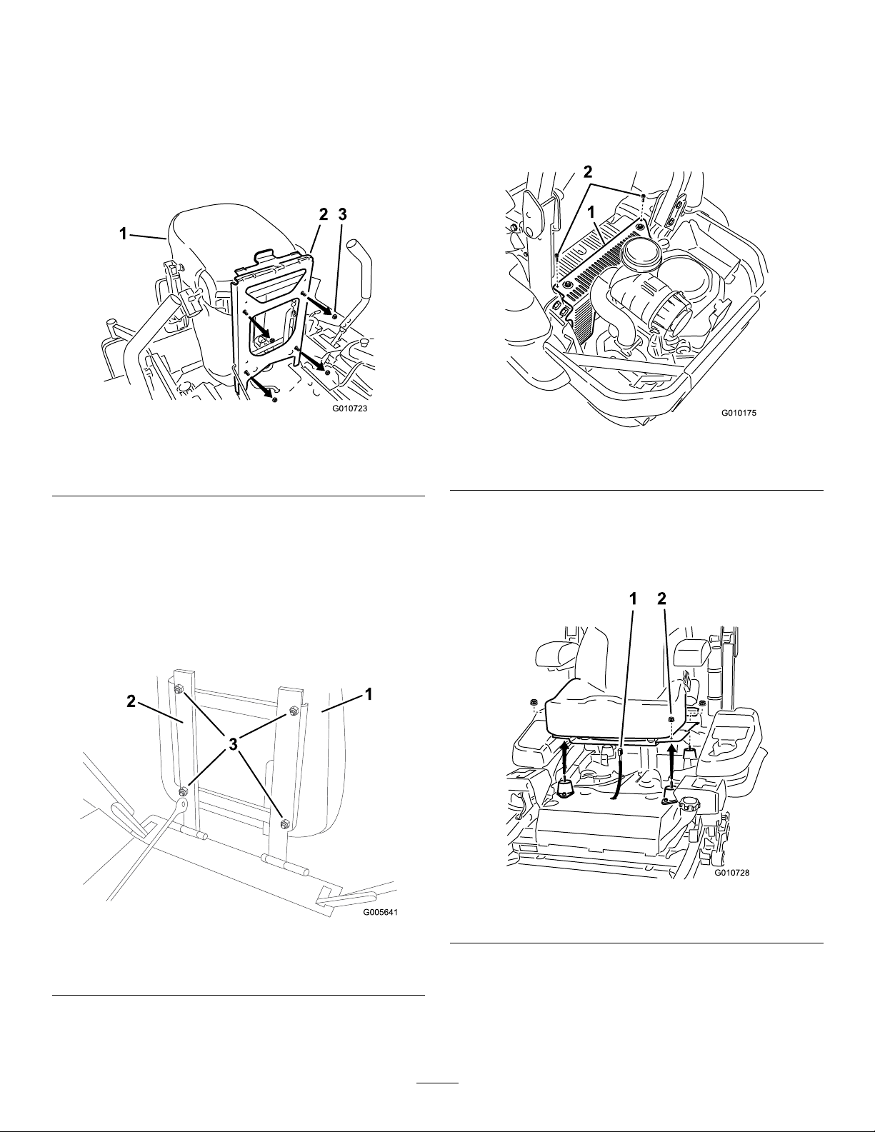
2.Removethenutsholdingtheseattotheseatframe
(Figure2).
3.Disconnectthewireharnessfromtheseatswitch.
4.Removetheseatfromtheframe.
Removinga3000SeriesorInternational
5000and6000SeriesZMasterMower
Seat(FixedSeat)
1.Forinternationalmachinesonly,removethehydraulic
unitshroudfromthemachine(Figure4).Save
hardwareandshroud.
Figure2
1.Seat
2.Seatframe
3.Nut
Removinga7000SeriesZMaster
MowerSeat
1.Unlatchtheseatandtiptheseatforward.
2.Removethenutsholdingtheseattotheseatframe
(Figure3).Retainthenuts.
3.Removetheseatfromtheframe.
Figure4
1.Hydraulicunitshroud2.Bolts
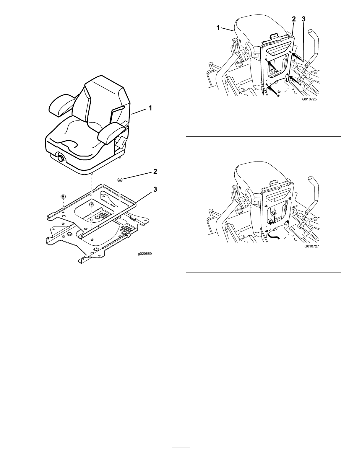
2.Removethe4angenutsholdingtheseattothe
machine(Figure5).
3.Unplugtheharnessconnectorfromtheseatswitch
locatedundertheseattowardsthefront(Figure5).
1.Seat
2.Seatframe
Figure3
Figure5
1.Harnessconnector2.Flangenuts
3.Nut
4.Removetheseatplatefromtheseatbyremovingthe4
spacersand4angenuts(Figure6).
2
Page 3
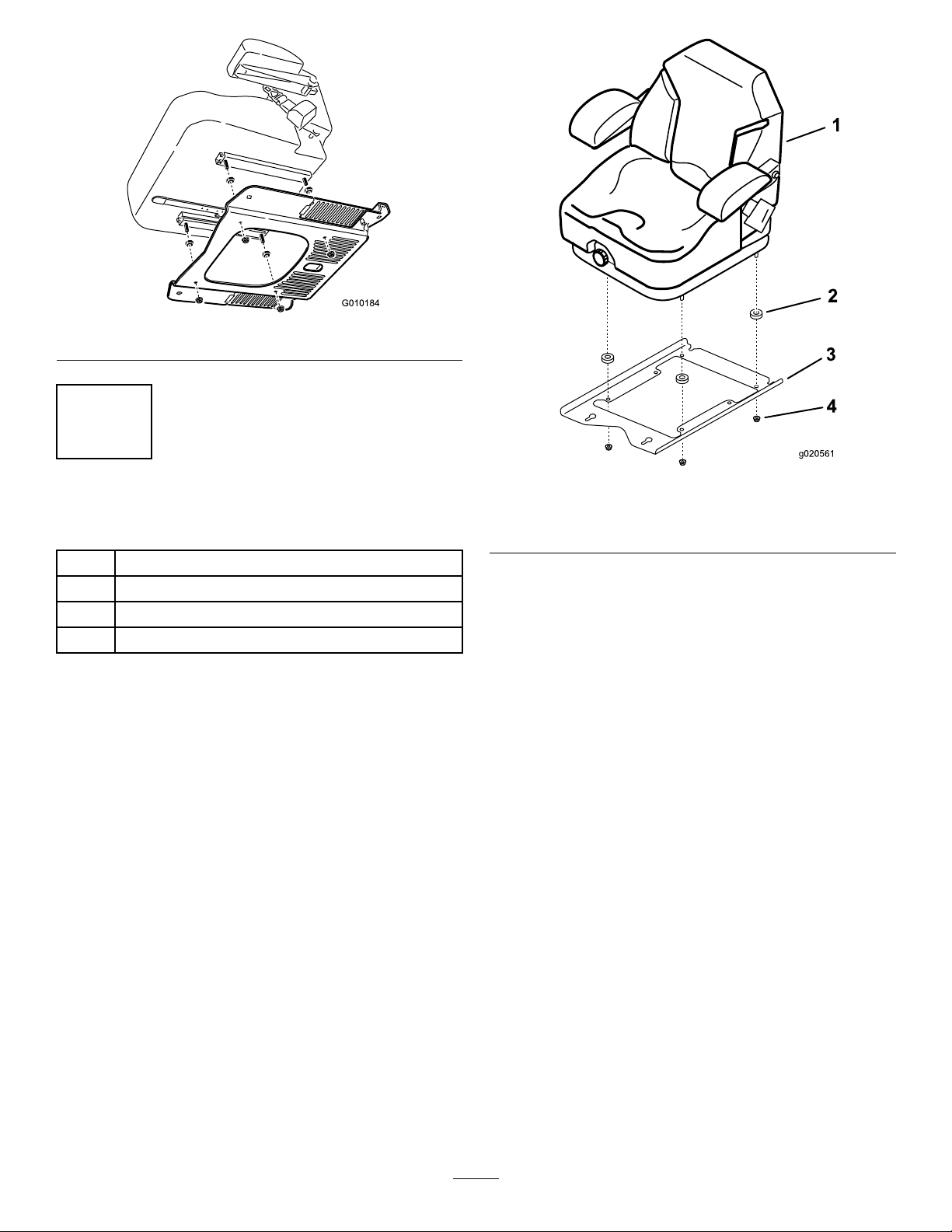
Figure6
g020561
4
2
InstallingtheSeat
Partsneededforthisprocedure:
1
Seat
4
Spacer
4
Flangenut(5/16inch)
4Plasticcabletie
Installinga2000SeriesZMasterMower
Seat
1.Removetheplasticpackingcoversguardingtheseat
studs.
2.Installaspacerontoeachseatstud(Figure7).
3.Securetheseatframetotheseatwith4angenuts
(5/16inch)(Figure7).
4.Torquethenutsto30.5N-m(22.5ft-lb).
Figure7
1.Newseat
2.Spacer
5.Plugtheharnessconnectorintotheseatswitchlocated
undertheseattowardsthefront(Figure13).
6.Carefullylowertheseatdownandensuretheharness
doesnotgetpinched.
7.Installtheplastictiestopreventthewireharnessfrom
beingpinched.
8.Installtheseattothemachineframebyaligningthe
frontnutswiththekeyholeintheseatplate.
9.Slidetheseatandseatplaterearwardtolockthefront
nutsintothekeyholeandtherearnutsintotheslots
Figure1).
(
10.Torquethenutsto47.5N-m(35ft-lb).
3.Seatframe
4.Nut
3
Page 4
Installinga5000or6000SeriesZ
g020559
MasterMowerSeat(DomesticOnly)
1.Tilttheseatframeup.
2.Removetheplasticpackingcoversguardingtheseat
studs.
3.Installaspacerontoeachseatstud(Figure8).
Figure9
1.Seat3.Flangenut(5/16inch)
2.Seatframe
7.Plugtheharnessconnectorintotheseatswitchlocated
undertheseat(Figure10).
Figure8
1.Newseat
2.Spacer
3.Seatframe
4.Positionthenewseatintotheseatframe(Figure9).
5.Securetheseattotheseatframewith4angenuts
(5/16inch)(Figure9).
6.Torquethenutsto29.8N-m(20ft.-lb).
Figure10
8.Carefullylowertheseatdownandensuretheharness
doesnotgetpinched.
9.Movetheseattothefurthestrearposition.
10.Installtheplastictiestopreventthewireharnessfrom
beingpinched.
4
Page 5
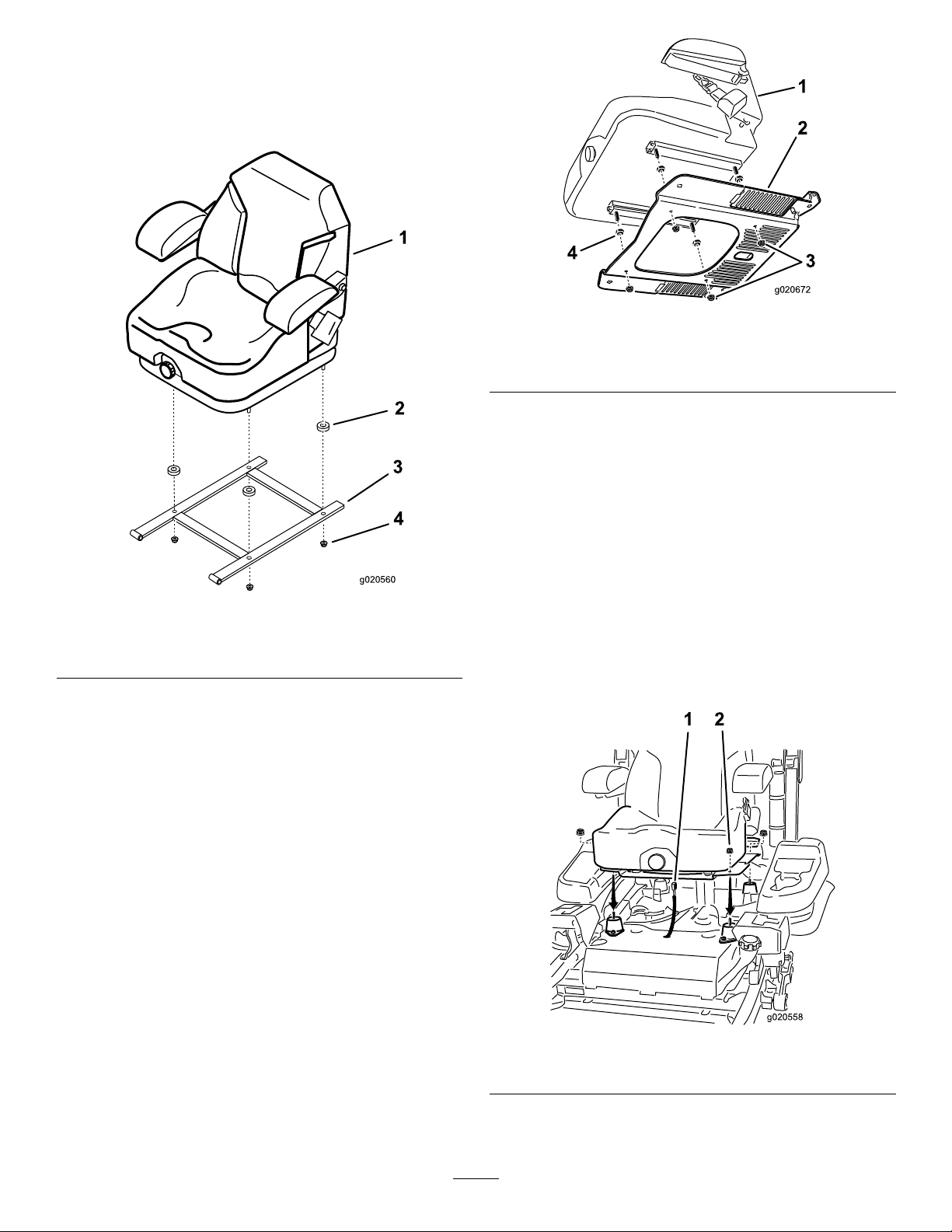
Installinga7000SeriesZMasterMower
g020560
4
g020672
4
g020558
Seat
1.Tilttheseatframeup.
2.Installaspacerontoeachseatstud(Figure11).
Figure11
1.Newseat
2.Spacer4.Flangenut(5/16inch)
3.Installtheseattotheseatframewith4angenuts
(5/16inch)(
Figure11).
3.Seatframe
Figure12
1.Seat3.Flangenut(5/16inch)
2.Seatplate4.Spacer
5.Plugtheharnessconnectorintotheseatswitchlocated
undertheseattowardsthefront.
6.Carefullylowertheseatdownandensuretheharness
doesnotgetpinched.
7.Movetheseattothefurthestrearposition.
8.Ensuretheharnessdoesnotgetpinched.
9.Installtheplastictiestopreventthewireharnessfrom
beingpinched.
10.Installtheseattothemachineframewiththepreviously
removednuts(
Figure13).
Note:Theseatmayneedtobetiltedtoallowaccess
tothethreading.
11.Torquethenutsto47.5N-m(35ft.-lb.).
4.Plugtheharnessconnectorintotheseatswitchlocated
undertheseattowardsthefront.
5.Carefullylowertheseatdownandensuretheharness
doesnotgetpinched.
6.Movetheseattothefurthestrearposition.
7.Installtheplastictiestopreventthewireharnessfrom
beingpinched.
Installinga3000SeriesorInternational
5000and6000SeriesZMasterMower
Seat
1.Removetheplasticpackingcoversguardingtheseat
studs.
2.Installaspacer(Figure12).
1.Harnessconnector
3.Securetheseattotheseatframewith4angenuts
(5/16inch)(Figure12)
4.Torquethenutsto22.5ft.-lb.(30.5N-m).
12.Forinternationalmachinesonly,installthehydraulic
unitshroudtothemachine(Figure14).
5
Figure13
2.Flangenuts(3/8inch)
Page 6
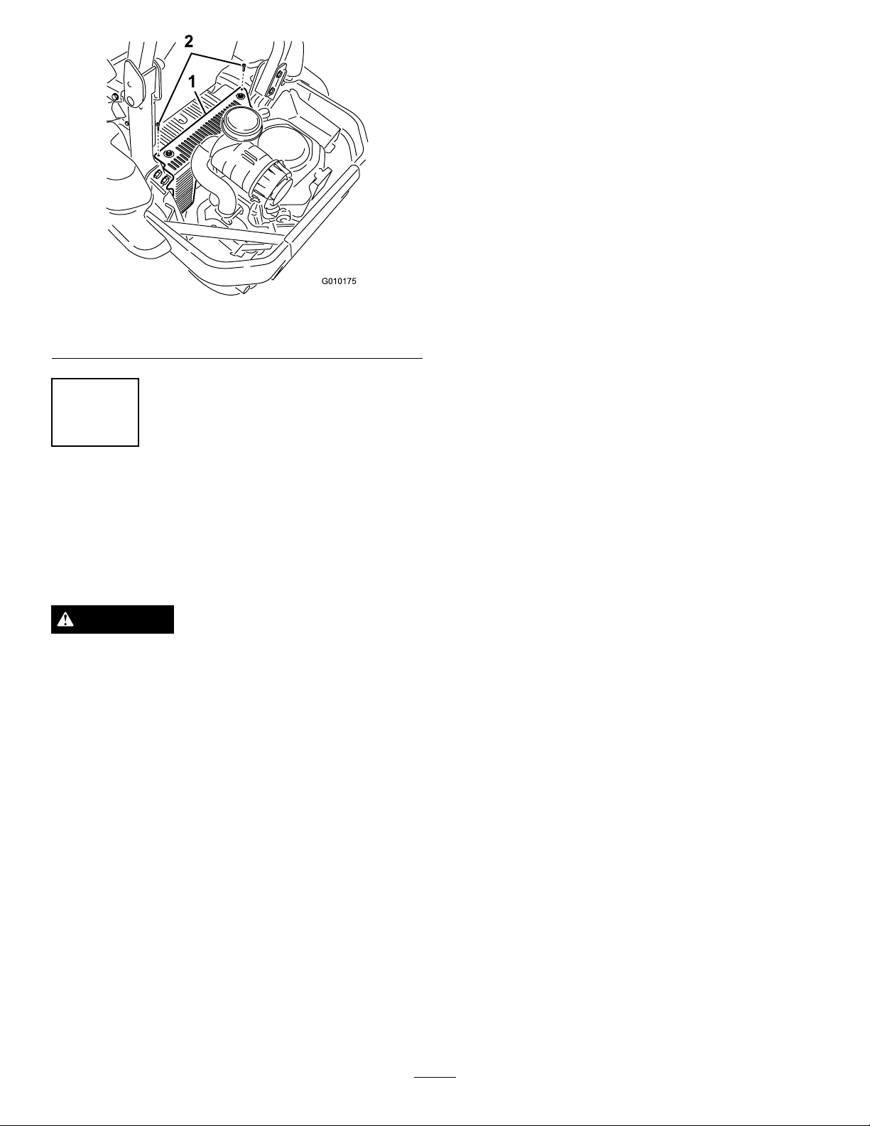
Figure14
1.Hydraulicunitshroud2.Bolts
componentisinthecorrectposition,atrianglewilllightup
inthecorrespondingsquare.
Testthesafetyinterlocksystembeforeyouusethemachine
eachtime.Ifthesafetysystemdoesnotoperateasdescribed
below,haveanAuthorizedServiceDealerrepairthesafety
systemimmediately.
1.Sittingontheseat,engagetheparkingbrakeandmove
thebladecontrolswitch(PTO)toon.Trystartingthe
engine;theengineshouldnotcrank.
2.Sittingontheseat,engagetheparkingbrakeandmove
thebladecontrolswitch(PTO)tooff.Moveeither
motioncontrollever(outofneutrallockedposition).
Trystartingtheengine;theengineshouldnotcrank.
Repeatforothercontrollever.
3.Sittingontheseat,engagetheparkingbrake,movethe
bladecontrolswitch(PTO)tooffandmovethemotion
controlleverstoneutrallockposition.Nowstartthe
engine.Whiletheengineisrunning,releasetheparking
brake,engagethebladecontrolswitch(PTO)andrise
slightlyfromtheseat;theengineshouldstop.
3
TestingtheSafetyInterlock System
NoPartsRequired
Procedure
CAUTION
Ifsafetyinterlockswitchesaredisconnectedor
damagedthemachinecouldoperateunexpectedly
causingpersonalinjury.
•Donottamperwiththeinterlockswitches.
•Checktheoperationoftheinterlockswitches
dailyandreplaceanydamagedswitchesbefore
operatingthemachine.
Thesafetyinterlocksystemisdesignedtopreventtheengine
fromstartingunless:
•Theparkingbrakeisengaged.
•Thebladecontrolswitch(PTO)isdisengaged.
•Themotioncontrolleversareintheneutrallocked
position
4.Sittingontheseat,engagetheparkingbrake,movethe
bladecontrolswitch(PTO)tooffandmovethemotion
controlleverstoneutrallockposition.Nowstartthe
engine.Whiletheengineisrunning,centereither
motioncontrolandmove(forwardorreverse);the
engineshouldstop.Repeatforothermotioncontrol.
5.Sittingontheseat,disengagetheparkingbrake,move
thebladecontrolswitch(PTO)tooffandmovethe
motioncontrolleverstoneutrallockposition.Try
startingtheengine;theengineshouldnotcrank.
Thesafetyinterlocksystemalsoisdesignedtostopthe
enginewhenthetractioncontrolsaremovedfromthelocked
positionwiththeparkingbrakeengagedorifyourisefrom
theseatwhenthePTOisengaged.
Thehourmeterhassymbolstonotifytheuserwhenthe
interlockcomponentisinthecorrectposition.Whenthe
6
Page 7
Operation
g019754
g019768
1
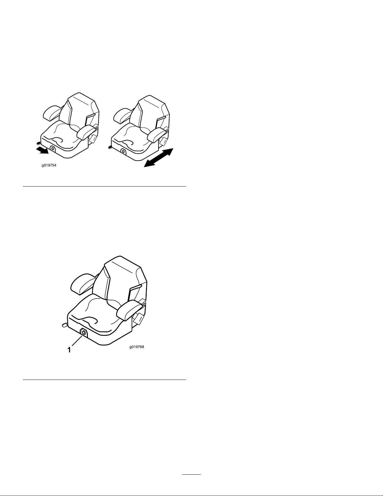
PositioningtheSeat
Theseatcanmoveforwardandbackward.Positiontheseat
whereyouhavethebestcontrolofthemachineandaremost
comfortable.
Toadjust,movetheleversidewaystounlockseat(Figure15).
Figure15
ChangingtheSeatSuspension
Theseatisadjustabletoprovideasmoothandcomfortable
ride.Positiontheseatwhereyouaremostcomfortable.
Toadjustit,turntheknobinfronteitherdirectiontoprovide
thebestcomfort(
1.Seatsuspensionknob
Figure16).
Figure16
7
Page 8

 Loading...