

Page 1

ElectricalServiceKit
2008andBeforeEmotion43Model21027LawnMower
ModelNo.117-4092
RemovingtheOldWire
Harness
NoPartsRequired
Procedure
Important:Theroutingofthenewwireharnessis
similartothatoftheold.Therefore,takenoteofthe
routingoftheoldwireharnessbeforeremovingit.
1.Liftupthereardeectortoexposethebatterycover.
2.Openthebatterycover,disconnectthebatteryfrom
theoldwireharness,andremovethebattery.
3.Tipthelawnmowerontoitsleftside.
4.Removetheblade.
FormNo.3362-334RevA
InstallationInstructions
Figure2
1.Engineconnector
5.Removethethreescrewsthatholdthebeltcover
inplace(Figure1).
Figure1
1.Beltcover
6.Rotatethebeltcovercounterclockwisetomoveit
outoftheway(Figure1).
7.Disconnecttheengineconnectorfromtheoldwire
harnessfrombehindtheengine(Figure2).
8.Disconnecttheignitionconnectorontheoldwire
harnessfromtheignitionswitchontheundersideof
theupperhandle(Figure3).
Figure3
1.Ignitionconnector
9.Removethecabletiesthatsecuretheoldwire
harnesstothehandle.
©2009—TheToro®Company
8111LyndaleA venueSouth
Bloomington,MN55420
Registeratwww.Toro.com.
10.Removeanddiscardtheoldwireharnessfromthe
mower.
Note:Removetheoldwireharnessthroughthe
bottomofthemowerhousing.
OriginalInstructions(EN)
PrintedintheUSA
AllRightsReserved
Page 2
InstallingtheNewWire
Harness
Partsneededforthisprocedure:
1Wireharness
1Battery
2Fuse
Procedure
1.Identifythefollowingitemsonthenewwireharness:
anadhesivetab,awhiteband,andfourconnectors:
onetothefuseholder,onetothebatteryconnector,
onetotheengineconnector,andonetotheignition
switch(Figure4).
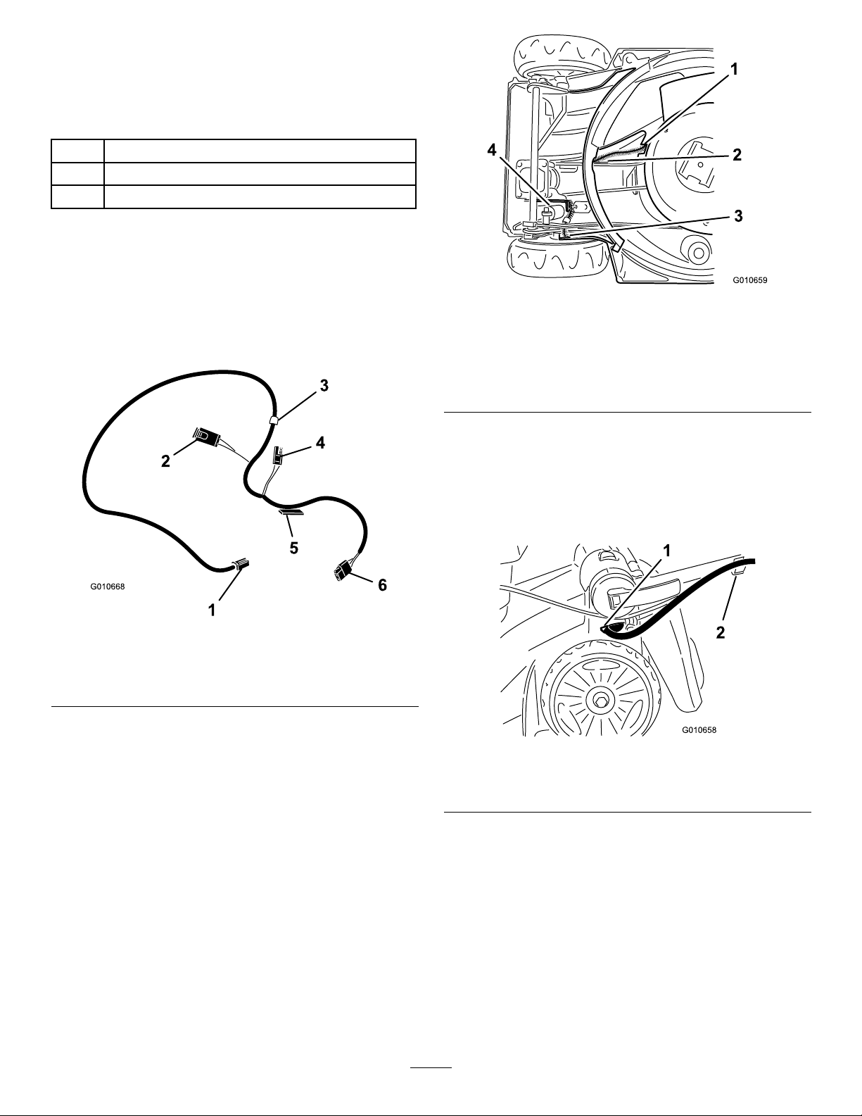
Figure5
1.Insertengineconnector
endofnewwireharness
here
2.Insertignitionswitch
connectorendofnewwire
harnesshere
3.Ignitionswitchconnector
exitsthemowerhousing
here
4.Height-of-cutcylinder
Note:Theignitionconnectorshouldcomeouton
theleftsideofthemowerhousingunderthehandle.
Figure4
1.Ignitionswitchconnector4.Batteryconnector
2.Fuseholder5.Adhesivetab
3.Whiteband6.Engineconnector
2.Installthenewwireharnessbythreadingtheignition
connectorendrstthroughtheopeninginthe
housingasshowninFigure5.
Note:Ensurethatthewhitestriponthenewwire
harnessisvisiblejustpasttheopeninginthemower
housing(Figure6).
Figure6
1.Openinginthemower
housing
2.Handleclip
3.Inserttheengineconnectorintotheopeningas
showninFigure5.
4.Connecttheengineconnectortotheengineas
showninFigure7.
2
Page 3

Figure7
1.Engineconnector
5.Tucktheengineconnectorandtheexposedwiring
harnessintothehousingbehindtheengine.
6.Locatethewireharness(withthefuseholderandthe
batteryconnector)insidethebatterycompartment
(Figure8).
Figure9
1.Fuse2.Fuseholder
8.Clipthefuseholderonthenewwireharnessonto
theupperleft-handcornerofthebeltcompartment
opening(Figure9).
9.Tuckthewireharnessbetweenthealuminumboss
andtheblackplasticrib(Figure8).
Note:Ensurethatthebatteryconnectoronthe
newwireharnessisinpositiontoconnecttothe
batterywhenitisinstalled.
Figure8
1.Wireharness(segment
wrappedwithelectrical
tape)
2.Batterycompartment
3.Beltcompartment
7.Insertthefuseholderrstinfrontofthe
height-of-cutcylinder(Figure5),thenworkitaround
thecylinderanddowntothebeltcompartment
(Figure8andFigure9).
10.Removemostoftheslackinthewireharness,
andsecurethewireharnesswiththeadhesivetab
(Figure10).
Important:Beforeattachingtheadhesivetab
onthewireharnesstothemowerhousing,
thoroughlycleantheareaonthehousingon
whichyouwillattachthetab.Wipethearea
withdenaturedalcohol(orequivalent)before
attachingthetabtothemowerhousing.
Note:Onceitisattached,theadhesivetabis
difculttoremovefromacleanedsurfaceand
cannotbereused.Therefore,takecarethatyou
properlylocatethetabonthemowerhousingbefore
attachingit.
3
Page 4

Figure10
1.Adhesivetab3.Drivebelt
2.Rib
17.Connecttheignitionconnectortotheignitionswitch
ontheundersideoftheupperhandle(Figure12).
Figure12
1.Ignitionconnector
18.Installthebatteryinthebatterycompartment.
19.Connectthebatterytothebatteryconnectoronthe
wireharness.
20.Insertthefuseinthefuseholder(Figure9).
21.Closethebatterycoverandthereardeector.
11.Rotatethebeltcoverclockwisetoreturnittoits
originalposition.
12.Securethebeltcoverwiththethreescrewsthatyou
previouslyremoved.
13.Installtheblade.
Note:Torquethebladeboltto50N-m.
14.Returnthemowertotheoperatingposition.
15.Insertthewireharnessintothehandleclip(Figure6).
16.Securethewireharnesstothehandlewith2cable
ties(Figure11).
1.Cabletieshere
Figure11
4
 Loading...