

Toro 117-3879 Installation Instructions
Roll-OverProtectionSystemKit
2010andAfterZ500RidingMowers
ModelNo.117-3879
LooseParts
Usethechartbelowtoverifythatallpartshavebeenshipped.
FormNo.3364-880RevA
InstallationInstructions
ProcedureDescription
1
2
3
4
1
InstallingtheRollOver
ProtectionSystem(ROPS)
Rollbar,rightsection1
Rollbar,leftsection
Rollbar,centersection1
Bolt,(3/8x1inch)
Curvedwasher
Flangenut,(3/8inch)
Bolt,(1/2x3–1/4inch)
Flangenut,(1/2inch)
Seatlatchcatch
Bolt(5/16x3/4inch)
Locknut(5/16inch)
Seatbeltkit
Seatframe
Locknut(3/8inch)
Bolt(3/8x5inches)
2.Looselyinstalltherightandleftrollbarsectionto
theframe,with8bolts(3/8x1inch),8curved
washers,and8angenuts(3/8inch)(Figure1).
Note:Thecurvewasherconemustbeinstalled
towardthebolthead.
Qty.
1
8
8
8
2
2
1
2
2
1Installtheseatbelt.
1
2
2
InstalltheRolloverProtectionSystem
(ROPS).
Replacetheseatlatchcatch.
Installthenewseatframe.
Use
Partsneededforthisprocedure:
1Rollbar,rightsection
1
Rollbar,leftsection
1Rollbar,centersection
8
Bolt,(3/8x1inch)
8
Curvedwasher
8
Flangenut,(3/8inch)
2
Bolt,(1/2x3–1/4inch)
2
Flangenut,(1/2inch)
Procedure
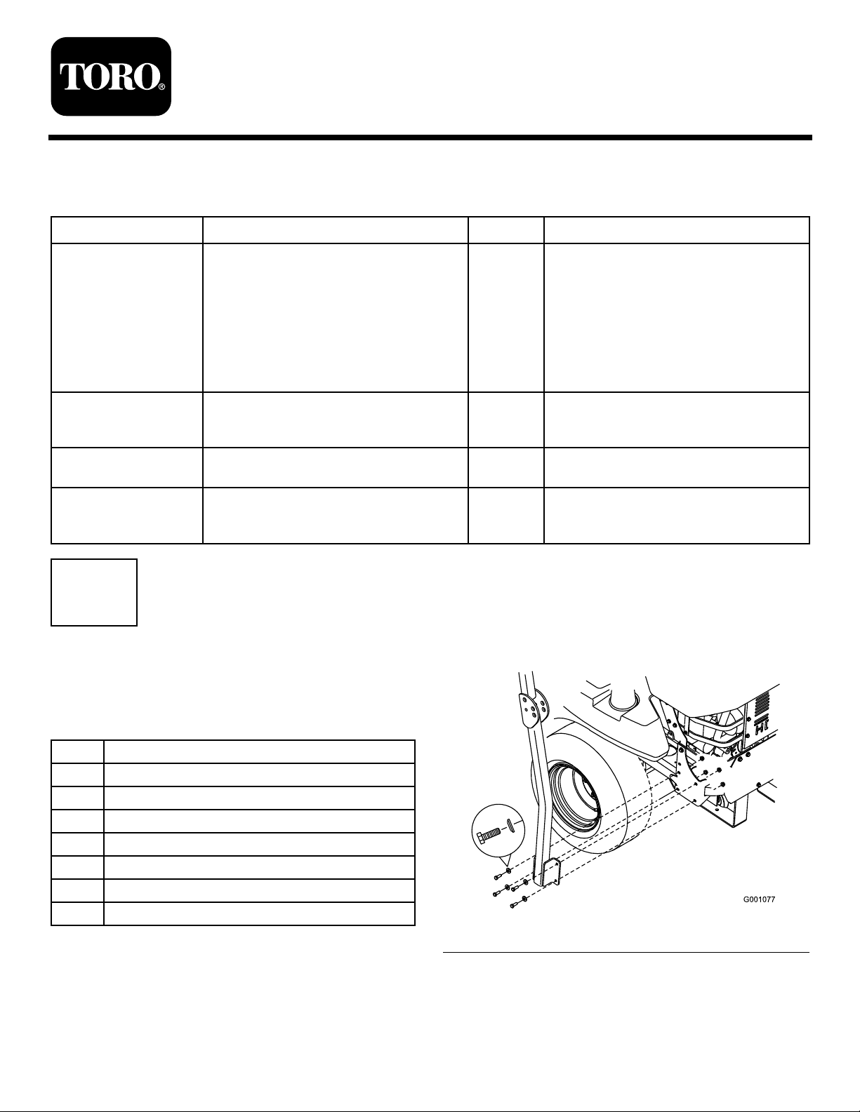
1.RemovetheexistingROPSfromthemachineframe
anddiscard(
©2010—TheToro®Company
8111LyndaleAvenueSouth
Bloomington,MN55420
Figure1).
Registeratwww.T oro.com.
Figure1
3.Installthelanyardclipsontothelongbolts(1/2x
3-1/4inch).
OriginalInstructions(EN)
PrintedintheUSA.
AllRightsReserved
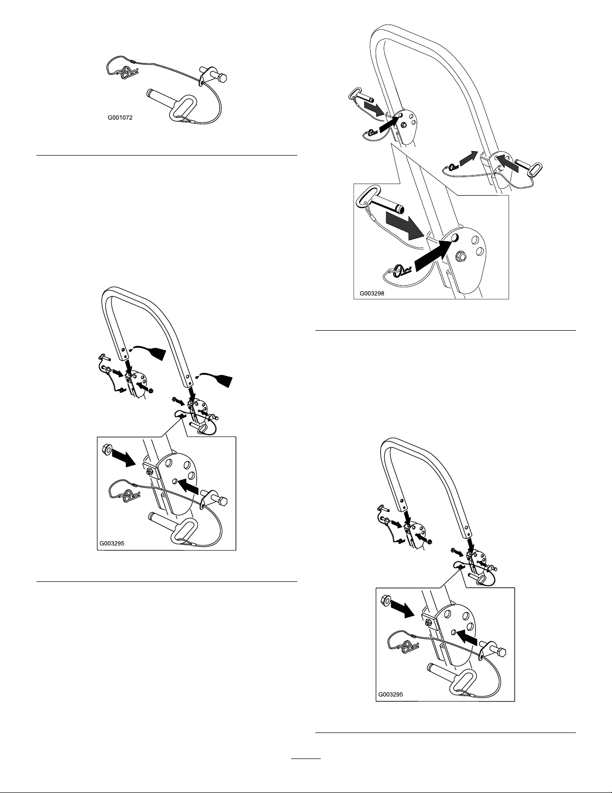
Note:Makesurethebenttabpointstowardthe
headofthebolt.
Figure2
4.Lightlyoiltheendsofthecenterrollbarsection.
5.Looselyinstallthecenterrollbarsectionusing2
bolts(1/2x3-1/4inch)and2angenuts(1/2inch).
Note:Makesuretheboltsareinstalledfromthe
outsideoftherollbar.
Note:Makesurethelanyardtabisinstalledasshow
andpointsforward.
Figure4
Figure3
6.Raisetherollbarintotheuprightpositionandsecure
itwiththepinsandhairpincotterpinsfastenedto
thelanyards
7.Torquealllowerfasteners,attachedtothemachine
frame,to30ft-lb.
8.Tightenthecenterrollbarbolts(1/2x3-1/4inch)
soitrotatesfreelywithsomeresistance.
Note:Nomorethanonethreadshouldbeexposed
outsidethenut.
Figure5
2
2
g013060
1 2
3
g013056
1
2
3 4
3
ReplacingtheSeatLatch
Catch
Partsneededforthisprocedure:
1
Seatlatchcatch
2
Bolt(5/16x3/4inch)
2
Locknut(5/16inch)
Procedure
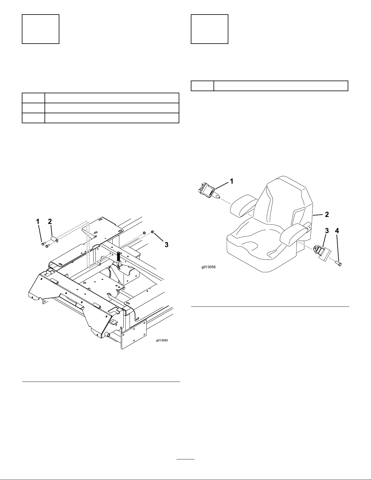
1.Tilttheseatforwardandremovetheexistinglatch
catch.
2.Installthenewseatlatchcatchtotheframewith2
bolts(5/16x3/4inch)and2locknuts(5/16inch)
asshown.
Note:Thebentpartofthelatchcatchneedsto
pointdownward.
InstallingtheSeatBelt
Partsneededforthisprocedure:
1
Seatbeltkit
Procedure
1.Tilttheseatforwardandremovetheexistingseat
beltreceiverandretractablebelt.
2.Installthereceiverpartoftheseatbelttotheseat
framewithasuppliedbolt.
3.Installtheretractablebelttotheseatwithasupplied
bolt.
1.Bolt(5/16x3/4inch)3.Locknut(5/16inch)
2.Latchcatch
Figure6
Figure7
1.Recieverwithsuppliedbolt3.Retractablebelt
2.Seat4.Suppliedbolt
3
 Loading...