

Page 1

ZStand
ZMaster
Deck
ModelNo.117-0350
ModelNo.117-0354
ModelNo.121-4811
Safety
SafetyandInstructionalDecals
Safetydecalsandinstructionsareeasilyvisibletotheoperatorandarelocatednearanyareaofpotential
danger.Replaceanydecalthatisdamagedorlost.
®
Kit
®
RidingMowerwith48-in,52-in,60-inor72-inMower
InstallationInstructions
FormNo.3372-957RevA
107-3969
1.Warning—readtheOperator'sManual.
2.Crushinghazard,mower—engagetheparkingbrake,stop
theengine,andremovetheignitionkeybeforeworking
underthemower.
©2012—TheToro®Company
8111LyndaleAvenueSouth
Bloomington,MN55420
Registeratwww.T oro.com.
OriginalInstructions(EN)
PrintedintheUSA.
AllRightsReserved
Page 2

Installation
LooseParts
Usethechartbelowtoverifythatallpartshavebeenshipped.
ProcedureDescription
1
2
3
4
5
ZStandhub
Latchbracket1
Bolt(3/8x1-1/2inches)
Flangenut(3/8inch)
Carriagebolt(3/8x1-1/4inches)(48,52
and60inchmachines)
Flangenut(3/8inch)(48,52and60
inchmachines)
Carriagebolt(3/8x1-1/4inches)(72
inchmachines)
Flangenut(3/8inch)(72inchmachines)
Bracket1
Anglebracket(72inchmachines)
Carriagebolt(3/8x1-1/4inches)
Flangenut(3/8inch)
Bolt(1/4x3/4inches)
Locknut(1/4inch)
Bracketpin1
Lanyard1
Cradlebracket
Pivotpin1
Outertube
Foot1
Clevispin
Hairpincotterpin2
Thrustwasher2
Lynchpin1
Footpedal1
Qty.
Use
1
1
1
4
4
6
6
1
2
2
1
1
1
1
2
AssembletheZStandHub
InstalltheZStandHub
InstalltheZStandBracket
InstalltheZStand
Installtheliftassistfootpedal(Machines
with48,52and60inchmowerdecks).
2
Page 3
1
2
AssemblingtheZStand
®
Partsneededforthisprocedure:
1
ZStandhub
1Latchbracket
1
Bolt(3/8x1-1/2inches)
1
Flangenut(3/8inch)
Procedure
1.Parkonalevelsurface,disengagethePTO,setthe
parkingbrake,removethekeyandchockorblockthe
drivewheels.
2.Turnofftheengine,removethekey ,andwaitforall
movingpartstostopbeforeleavingtheoperating
position.
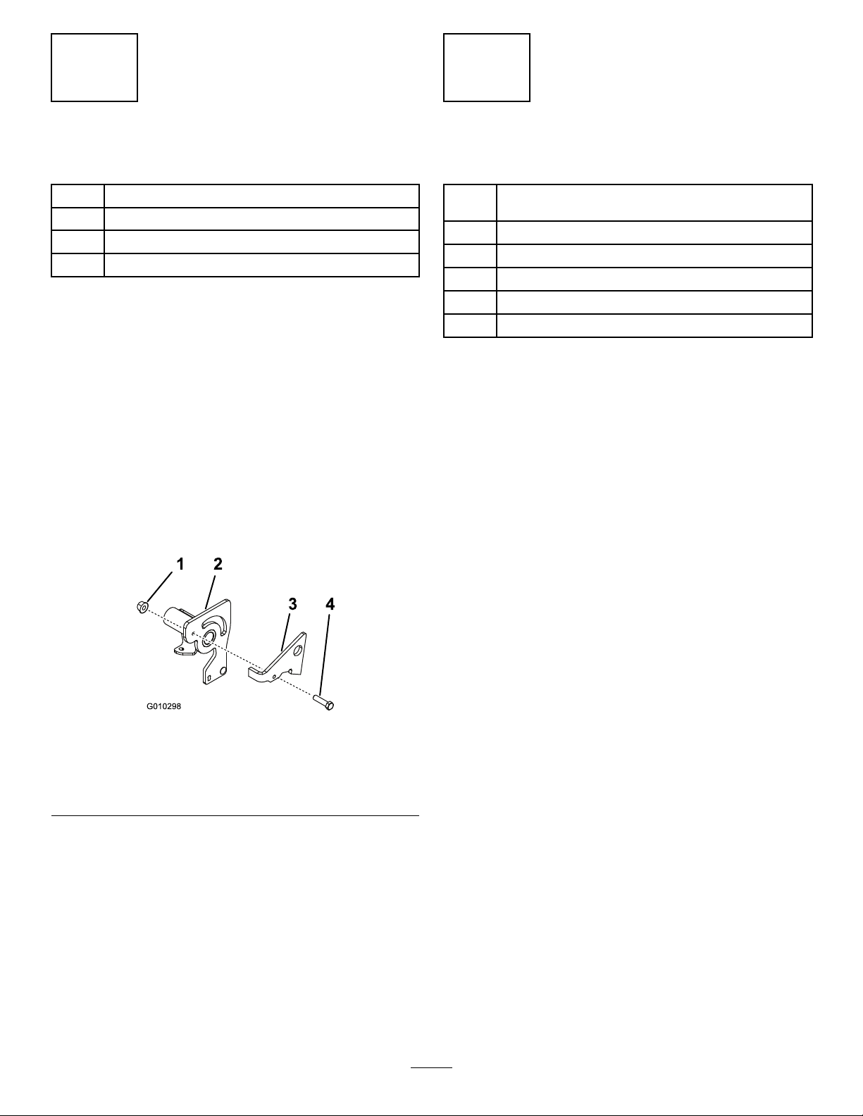
3.InstallthebracketlatchtotheZStandhubwitha
bolt(3/8x1-1/2inches)andaangenut(3/8inch)
Figure1).
(
4.Tightenthenutandbolt.Then,unscrewitonefull
turnoruntilthelatchwillfreelyrotate(Figure1).
Hub
InstallingtheZStandHub
Partsneededforthisprocedure:
Carriagebolt(3/8x1-1/4inches)(48,52and60inch
4
machines)
4
Flangenut(3/8inch)(48,52and60inchmachines)
6
Carriagebolt(3/8x1-1/4inches)(72inchmachines)
6
Flangenut(3/8inch)(72inchmachines)
1Bracket
1
Anglebracket(72inchmachines)
Procedure
1.PlacetheZStandhubontherightfrontframeas
showninFigure2.
2.For48,52and60inchmowers,installtheZStand
hubtotheframewiththebottombracket,4carriage
bolts(3/8x1-1/4inches)and4angenuts(3/8
inch)(Figure2).
3.For72inchmowers,installtheZStandhubtothe
framewiththebottombracket,theanglebracket,6
carriagebolts(3/8x1-1/4inches)and6angenuts
(3/8inch)(Figure2andFigure3).
Figure1
48,52and60inchshown
1.Flangenut(3/8inch)
2.ZStandhub4.Bolt(3/8x1-1/2inches)
3.Bracketlatch
3
Page 4
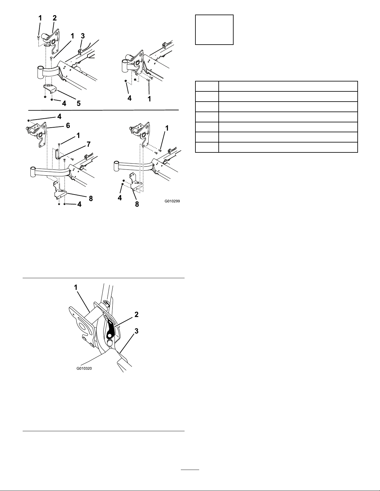
Figure2
1.Carriagebolt(3/8x1-1/4
inches)
2.ZStandhub(48,52and
60inchmowers)
3.Rightsideofmachine
4.Flangenut(3/8inch)8.Bottombracket(72inch
5.Bottombracket(48,52and
60inchmowers)
6.ZStandhub(72inch
mowers)
7.Anglebracket
mowers)
3
InstallingtheZStandBracket
Partsneededforthisprocedure:
2
Carriagebolt(3/8x1-1/4inches)
2
Flangenut(3/8inch)
1
Bolt(1/4x3/4inches)
1
Locknut(1/4inch)
1Bracketpin
1Lanyard
1
Cradlebracket
Procedure
Note:Ensurethegrassdeectorisinstalledinthelower
holesinthemowerdeckbrackets.
1.PlacetheZStandcradlebracketontotheleftfront
frameasshowninFigure4.
2.InstalltheZStandcradlebrackettotheframewiththe
cradlebracket,2carriagebolts(3/8x1-1/4inches)
and2angenuts(3/8inch)(
EnsurethecorrectholesareusedasshowninFigure4.
3.Installthelanyardtobracketpin.Uselargeloopon
lanyard(Figure4).
4.Installthelanyardwithabolt(1/4x3/4inches)and
locknut(1/4inch)(Figure4).
Figure4).
1.ZStandhubinstalled(72
inchmowers)
2.Anglebracket(72inch
mowers)
Figure3
72inchhubonly
3.Rightsideofmachine
4
Page 5

Figure4
1.Carriagebolts(3/8x1-1/4
inches)
2.Frame(48,52and60inch
machines)
3.Cradlebracket8.Bolt(1/4x3/4inches)
4.Flangenut(3/8inch)9.Correctholefor48and52
5.Frame(72inchmachines)10.Correctholefor60and72
6.Lanyard
7.Nut(1/4inch)
inchmowers
inchmowers
4
InstallingtheZStand
Partsneededforthisprocedure:
1Pivotpin
1
Outertube
1Foot
2
Clevispin
2Hairpincotterpin
2Thrustwasher
1Lynchpin
Procedure
1.Installthepivotpintotheoutertubewithaclevispin
andhairpincotterpin(Figure5).
Figure5
1.Clevispin
2.Pivotpin5.Foot
3.Outertube
4.Hairpincotterpin
3.Placeathrustwasherontothepivotpin(Figure6).
4.InsertthepivotpinintotheZStandhub.
Note:Wheninsertingthepivotpin,makesurethe
positionofslotintubeisasshowninandmakesure
thechamferisfacingforward(
Figure6).
5.Placeathrustwasherontothepivotpinandsecureit
withalynchpin(Figure6).
Figure6
1.Lynchpin
2.Thrustwasher
3.Hubassembly
4.ZStandassembly
5.Topviewofoutertubeand
chamferfacingforward
2.Placethefootpartofstandintotheoutertube.Align
holesandsecurewithaclevispinandhairpincotter
(
Figure5).
5
Page 6
g018228
1
2
3
Operation
5
InstallingtheFootPedal
(Machineswith48,52and60
inchMowerDecks)
Partsneededforthisprocedure:
1Footpedal
Procedure
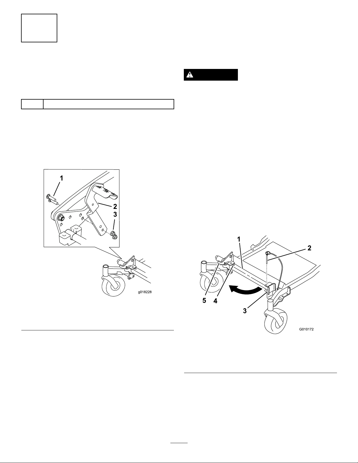
1.Removetheexistingfootpedalfromthemachine.Save
theexistinghardware.
2.Installthenewfootpedalontothemachineusingthe
existinghardware().
UsingtheZStand®
TheZStand®raisesthefrontendofthemachinetoallow
youtocleanthemowerandremovetheblades.
WARNING
Themachinecouldfallontosomeoneandcause
seriousinjuryordeath.
•Useextremecautionwhenoperatingthe
machineontheZStand®.
•Useonlyforcleaningthemowerandremoving
theblades.
•DonotkeepthemachineontheZStandfor
extendedperiodsoftime.
•Alwaysturntheengineoff,settheparking
brake,andremovethekeybeforeperforming
anymaintenancetothemower.
DrivingupontotheZStand
Important:UsetheZStandonalevelsurface.
Figure7
1.Existingbolts3.Existingnuts
2.Newfootpedal
1.Raisethemowertothetransportposition.
2.Removethebracketpin(
1.ZStand4.Bottomofslot
2.BracketPin5.Latch
3.Bracket
3.Raisethelatch.Swingthestandfootoutfrontand
slidestandtowardmachine,intothebottomofslot
(Figure8andFigure9).
Figure8).
Figure8
4.LengthentheZStandbyremovingtheclevispinand
hairpincotterpinfromtheoutertubeandslidingthe
footout.
6
Page 7

5.Aligntheholesandinstalltheclevispinandhairpin
cotterpin.
Figure9
1.ZStand(Positionedin
slot)
2.Crackinsidewalkorturf
3.Latchrestingonpivottab
6.Setthefootofstandonthegroundandrestthelatch
onthepivottab(Figure9).
7.Starttheengineandputitathalfthrottle.
Note:Forbestresults,placethefootofstandinto
seamsinsidewalksorintotheturf(Figure9).
8.Driveontothestand.Stopwhenthelatchdropsover
thetabintothelockedposition(Figure9).Onceonto
thestand,engagetheparkingbrakeandtunoffthe
engine.
9.Chockorblockthedrivewheels.
WARNING
Parkingbrakemaynotholdmachineparked
onZStandandcouldcausepersonalinjury
orpropertydamage.
Figure10
1.ZStand
2.Latch4.Unlockedposition
3.Lockedposition
3.Starttheengineandplaceitathalfthrottle.Disengage
theparkingbrake.
4.Slowlydrivebackwardsoffofthestand.
5.ShortentheZStandbyremovingtheclevispinand
hairpincotterpinfromtheoutertubeandslidingthe
footin.
6.Aligntheholesandinstalltheclevispinandhairpin
cotterpin.
7.Returnthestandtoitsrestposition(
Figure8).
DonotparkonZStandunlesswheelsare
chockedorblocked.
10.Performthemaintenance.
DrivingofftheZStand
1.Removethechocksorblocks.
2.Raisethelatchtotheunlockedposition(Figure10).
7
Page 8

 Loading...