

Page 1

DuelFuelPumpKit
forDFIZMaster
ModelNo.115–7490
Note:Determinetheleftandrightsidesofthemachinefromthenormaloperatingposition.
®
Mowers
Installation
LooseParts
Usethechartbelowtoverifythatallpartshavebeenshipped.
FormNo.3362-988RevA
InstallationInstructions
ProcedureDescription
1
2
3
Nopartsrequired
Fuelselectorvalvewithhosesandwire
harness
Hoseclamp2
Fuelselectorbracket1
Switch
Fuelpump1
Carriagebolt(1/4x3/4inch)
Carriagebolt(1/4x5/8inch)
Washer(1/4inch)
Nut(1/4inch)
Plastictie4
Coverplate
Fuelpumpbracket1
Lefthandfuelpumpbracket
Bolt(3/8x2-1/4inch)
Curvedwasher
Spacer
Bolt(3/8x7/8inch)
Flatwasher(3/8inch)
Shortfuelhose(3inch(7.6cm))
Longfuelhose
Hoseclamp10
Qty.
Use
–
1
1
2
2
4
4
1
1
2
2
2
2
2
2
1
Preparethemower.
Changingthefuelhoses.
Installthefuelpumps.
1
PreparingtheMower
NoPartsRequired
Procedure
1.Thoroughlycleanmower.Alldebrismustbe
removedtoensurethekitwilltproperly .
©2009—TheToro®Company
8111LyndaleAvenueSouth
Bloomington,MN55420
Registeratwww.T oro.com.
2.Repairallbentordamagedareasandreplaceany
missingparts.
3.Drainthefuelfrombothfueltanks.
OriginalInstructions(EN)
PrintedintheUSA.
AllRightsReserved
Page 2
2
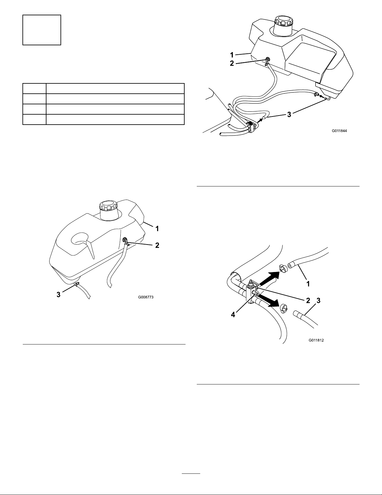
ChangingtheFuelHoses
Partsneededforthisprocedure:
1Fuelselectorvalvewithhosesandwireharness
2Hoseclamp
1Fuelselectorbracket
1
Switch
Procedure
1.Loosenboththelefthandandrighthandlowerfuel
tankttingsandrotatethemforward.Keepthem
looseforeaseofassembly.
2.Removebothfuelhosesontherighthandfueltank
(Figure1).
Figure1
Righthandtankshown
Figure2
Lefthandtankshown
1.Lefthandfueltank
2.Upperfueltankconnection
(Donotremovehosehere)
3.Removehosehere
4.Disconnectthereturnhosefromtheengineatthe
fuelselectorvalve.Thisislocatedatthecentertop
port(Figure3).
5.Disconnectthelefthandtopfuelhoseatthefuel
selectorvalve.Thisislocatedatthelefthandtop
port(Figure3).
1.Righthandfueltank3.Lowerfueltankconnection
2.Upperfueltankconnection
3.Removethelowerfuelhoseonthelefthandfuel
tank.DoNOTremovethetopfuelhoseontheleft
handfueltank(Figure2).
Figure3
1.Returnhosefromthe
engine
2.Centertopport4.Lefthandtopport
3.Lefthandtopfuelhose
6.Removetheexistingfuelselectorvalveandthefuel
selectorvalvebracket.Savethenutandbolt.
7.Removethefuelhosefromthefuelselectorvalveto
fuellter(Figure4).
8.Removethefuelhosefromthefuelltertothefuel
pump(Figure4).
9.Removethefuelhosefromthefuelpumptothe
engine(Figure4).
2
Page 3
10.Disconnectthefuelpumpfromthewireharness.
Rememberthisconnectionbecausethenewwire
harnesswillconnecthere(Figure4).
11.Removefuelpumpandsetasideforinstallationlater
(Figure4).
Figure4
1.Selectorvalve
2.Hosefromthefuelselector
valvetofuellter
3.Wireharnessconnection
4.Hosefromthefuelpump
totheengine
5.Fuelpump
6.Hosefromthefuellterto
fuelpump
7.Fuellter
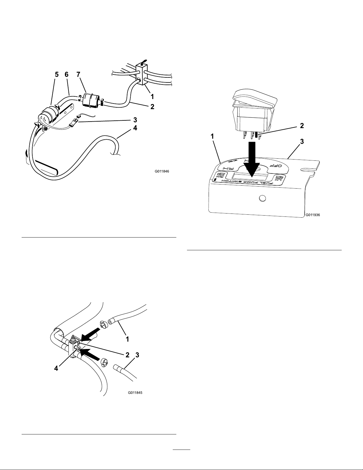
12.Installthefuelhosefromthetoplefthandfueltank
tothenewselectorvalveatthelefthandtopport
withanewhoseclamp.Ensuretheclampistight
(Figure5).
13.Installthereturnfuelhosefromtheenginetothe
newselectorvalveatthecentertopportwithanew
hoseclamp.Ensuretheclampistight(Figure5).
14.RoutethefuellinesasshowninFigure7.
15.Locatethelongerofthetwonewrighthandfuel
hosesattachedtothefuelselectorvalveassembly
andconnectittotheupperrighthandtanktting
(Figure7).
16.Installtheswitchintothebracketensuringthe
locatingpinonthebottomoftheswitchisonthe
leftsideoftheunit(Figure6).
Figure6
1.Righthandside
2.Locatingpin
3.Lefthandside
17.Installthenewfuelselectorvalvetothenewbracket
andconnectthewireharnesstotheswitch.
18.Installthenewbrackettothemachineusingthe
existingboltandnut(Figure7).
Figure5
1.Returnhosefromthe
engine
2.Centertopport4.Lefthandtopport
3.Lefthandtopfuelhose
3
Page 4

1.Existingbolt
2.Existingnut
3.Routethehoses
Figure7
4.Newfuelselectorvalve
5.Upperrighthandfueltank
connection
3
InstallingtheFuelPumpsand
WireHarness
Partsneededforthisprocedure:
1Fuelpump
2
Carriagebolt(1/4x3/4inch)
2
Carriagebolt(1/4x5/8inch)
4
Washer(1/4inch)
4
Nut(1/4inch)
4Plastictie
1
Coverplate
1Fuelpumpbracket
1
Lefthandfuelpumpbracket
2
Bolt(3/8x2-1/4inch)
2
Curvedwasher
2
Spacer
2
Bolt(3/8x7/8inch)
2
Flatwasher(3/8inch)
2
Shortfuelhose(3inch(7.6cm))
1
Longfuelhose
10Hoseclamp
Procedure
1.Assemblethenewfuelpumptothecoverplateand
righthandfuelpumpbracketwith2carriagebolts
(1/4x3/4inches),2washers(1/4inch)and2lock
nuts(1/4inch)(Figure8).
Note:Thefuelpumpmustbeassembledasshown
inFigure8withthewiresontherightside.
4
Page 5

Figure8
1.Righthandfuelpump
bracket
2.Carriagebolt(1/4x3/4
inch)
3.Coverplate
4.Newfuelpump9.Wirescomingoutoffuel
5.Washer(1/4inch)
6.Locknut(1/4inch)
7.Fuelhose(3inch(7.6cm))
8.Hoseclamp
pump
2.Installashortfuelhosetothefuelpumpwithahose
clamponthesidethatthewiresdonotcomeout
ofthepump.
Note:Ensurethesmallfuelhoseisinstalledonthe
endofthefuelpumpthatdoesNOThavewires
comingoutofit.
3.Raiseuptherighthandsideofthemachineand
loweritontoajackstand.Removerighthandtire.
4.Removeboltsandnutsholdingtherighthandbrake
crossshaftbearingtotheframe.
Figure9
1.Existingnut
2.Rightsideofmachine5.Washer(3/8inch)
3.Newfuelpumpassembly6.Bolt(3/8x7/8inches)
4.Shortfuelhoseinstalled
7.Engagetheparkingbrake.
8.Onthelefthandsideofthemachine,removethe
upperfronttwofrontcarrierframebolts.
9.Installlefthandpumpbracketwith2spacers
betweenthecarrierframeandbracketusingthe
nutspreviouslyremovedand2newbolts(3/8x
2-1/4inches)and2newcurvedwashers(3/8inch)
(Figure10).
Note:Temporarilyreleasethebrakestoeasethe
removaloftheboltsandnutsholdingthecrossshaft.
5.Connectthenewfuelhosefromthefuelselector
valvetothewiresideofthefuelpumpwithahose
clampandtightentheclamp.
6.Installnewfuelpumpandbracketassemblyusing
thenutspreviouslyremovedandnewbolts(3/8x
7/8inch)andatwashers(3/8inch)(Figure9).
Don’ttightenthefasteners.
Beforetighteningthefasteners,connecttheshort
fuelhoseonthefuelpumpandtothettingon
thebottomofthefueltankwithahoseclampand
tightentheclamp.Ensurethefuellineisnotkinked
onceeverythingistightened.
Figure10
1.Lefthandpumpbracket4.Spacer
2.Frontofmachine5.Washer(3/8inch)
3.Nut(3/8inch)6.Bolt(3/8x2-1/4inches)
10.Installashortfuelhosetofuelpumpremovedearlier
withahoseclampandtightentheclamp(Figure11).
Note:Installthesmallfuelhoseontheendofthe
fuelpumpthatdoesNOThavewirescomingout
ofit.
11.Routethenewfuelhosefromthefuelselectorvalve
throughtheframeandbracketasshowninFigure12
5
Page 6

andFigure13andconnectittothewiresideofthe
fuelpumpwithahoseclamp.Tightentheclamp.
12.Positionthefuelpumpintoplaceandconnectthe
shortfuelhose(3inch(7.6cm))tothettingonthe
bottomoftheleftfueltankwithahoseclampand
tightentheclamp.Ensurethefuellineisnotkinked
onceeverythingistightened(Figure11).
13.Assemblethefuelpumptothelefthandfuelpump
bracketwith2carriagebolts(1/4x5/8inch),2nuts
(1/4inch),and2washers(1/4inch)(Figure11).
14.Installfuellterremovedpreviouslytothe3inch
hoseattachedtothebottomcenterportofthe
selectorvalvewithahoseclamp.
Note:Thefuelltermustbeinstalledasshown,
withlargerpartoftheltertowardtherearofthe
unit.
20.Connectnewwireharnesstotherighthandfuel
pumpandfoldanyextrawireanduseaplastictieto
securethefoldedwire(Figure12).
21.Plugthenewwireharnesstomainwireharnesson
unit.Thisisthesameconnectionthatwasusedfor
theexistingfuelpump(Figure12).
Figure11
1.Leftthandfuelpump
bracket
2.Washer(1/4inch)6.Existingfuelpump
3.Locknut(1/4inch)7.Carriagebolt(1/4x5/8
4.Hoseclamp
5.Fuelhose(3inch(7.6cm))
inch)
15.Connectthenewlongfuelhosetothelterandthe
engineusing2newhoseclamps.Ensurethehoseis
routedthesameastheonepreviouslyremoved.
16.Checkandtightenallboltsandallfuelhoseclamps.
17.Tightenbothlowerfueltankttings.
Figure12
1.Newharness
2.Existingmachineharness
3.Switch
22.Looselyinstallthefuelhoseassemblytothebrake
crossshaftasshownwith2plasticties(Figure13).
23.Useaplastictietosecurethefuelhosethrough
thecenterholesinthelefthandfuelpumpbracket
(Figure13).
18.Installtherighthandtire.Removethejackstand.
19.Routethenewwireharnesstothelefthandfuel
pumpthroughtheframefollowingthepathofthe
fuellineandconnectittothefuelpump.Keep
thefuelpumpwiresinsidethelefthandfuelpump
bracket.Pullthemtowardstherearandconnectthe
newwireharness(Figure12).
6
Page 7

1.Brakecrossshaft
24.Filleachtankwithagallonoffuel.
25.Beforeoperatingthemachinecheckforleaksatall
hoseconnections.Ensurenofuelleaksoccurwhen
themachineisrstrun.
Figure13
2.Plasticties
7
Page 8

Operation
UsingtheFuelSelectorValve
andSwitch
Note:Determinetheleftandrightsidesofthemachinefromthenormaloperatingposition.
Theelectricalswitchmustbesettothesamefueltank
asthemechanicalfuelselectorvalve.
Figure14
1.Switch2.Mechanicalfuelselectorvalve
8
 Loading...