

Page 1
Heavy-DutyAirFilterKit
forTRXTrenchers
ModelNo.115-4029
LooseParts
Usethechartbelowtoverifythatallpartshavebeenshipped.
FormNo.3360-523RevA
InstallationInstructions
ProcedureDescription
1
2
3
4
Nopartsrequired
Intakepipe1
Gasket
Breathertube1
Enginemountingbracket1
Canisterassembly
Flange-headbolt3
Washer2
Lockwasher2
Nut2
Plug1
Largeairhose1
Hoseclamp3
Weathercap1
1
RemovingtheExistingAir
Qty.
–
1
1
4.Cleanalldirtanddebrisfromthemachine.
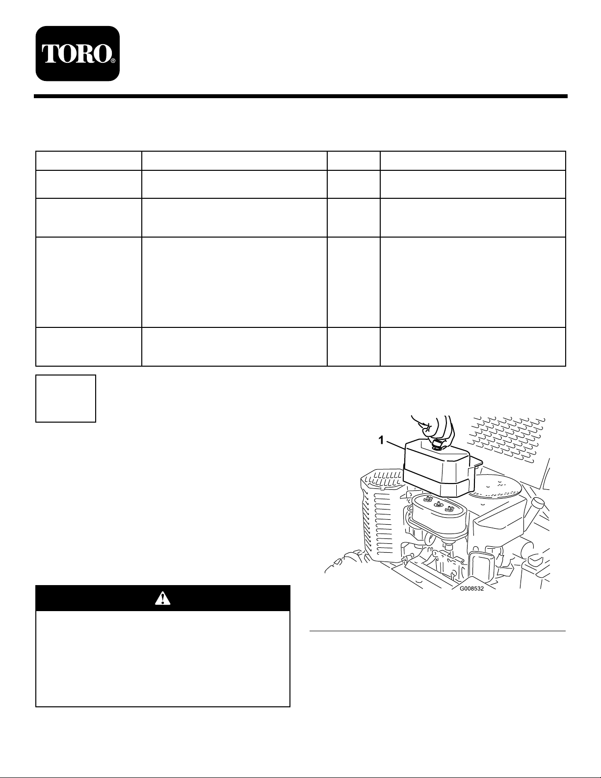
5.Removetheaircleanercover(Figure1).
Removetheexistingaircleaner.
Installtheintakepipe.
Installtheaircleaner.
Connecttheaircleanertotheengine.
Use
Cleaner
NoPartsRequired
Procedure
1.Stopthemachineonalevelsurface,stoptheengine,
removetheignitionkey,andlowertheboom.
2.Allowtheenginetocoolcompletelybefore
continuing.
Iftheenginehasbeenrunning,themufer
andmuferguardwillbehotandcouldburn
you.Thisprocedurerequiresyoutotouchthe
muferguard.
Allowtheengineandmufertocoolcompletely
beforeinstallingthiskit.
3.Closethefuelshutoffvalve.
©2008—TheToro®Company
8111LyndaleAvenueSouth
Bloomington,MN55420
Registeratwww.T oro.com.
Figure1
1.Aircleanercover
6.Removeanddiscardthebreathertubefromthe
engineandcarburetor(Figure2).
OriginalInstructions(EN)
PrintedintheUSA.
AllRightsReserved
Page 2
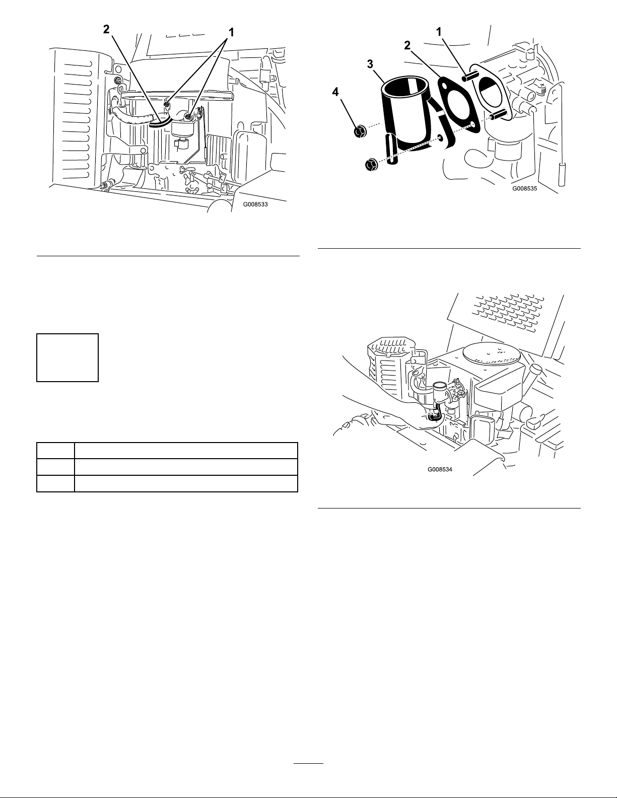
Figure2
1.Flangenuts2.Breathertube
1.Carburetorstud
2.Gasket
Figure3
3.Intakepipe
4.Flangenut
7.Removeandsavethe2angenutssecuringtheair
cleaner(Figure2).
8.Removeanddiscardtheaircleanerandgasketfrom
thecarburetor.
2
InstallingtheIntakePipe
Partsneededforthisprocedure:
1Intakepipe
1
Gasket
1Breathertube
Procedure
1.Installanewgasketandintakepipeontothe
carburetorusingtheangenutsyouremoved
previously(Figure3),andtorquetheangenutsto
52to69in-lb(6to7.5N-m).
2.Installthenewbreathertubebetweentheintakepipe
andtheengine(Figure4).
Figure4
2
Page 3

3
InstallingtheAirCleaner
Partsneededforthisprocedure:
1Enginemountingbracket
1
Canisterassembly
3Flange-headbolt
2Washer
2Lockwasher
2Nut
1Plug
Procedure
1.Assembletheenginemountingbrackettothe
canistermountingbracketusing2ange-headbolts,
washers,lockwashers,andnutsasshowninFigure5.
Figure6
1.Bolt
2.Muferguard
4.Removetheboltsecuringtheuppercornerofthe
valvecoverontheleftsideofthemachine(Figure7).
Figure5
1.Enginemountingbracket5.Lockwasher
2.Canistermountingbracket
3.Flange-headbolt7.Plug
4.Washer
6.Nut
2.Installtheplugintothediagnosticportontheair
cleanercanister(Figure5).
3.Removeandsavetheboltontheupperandinner
edgeofthemuferguardasshowninFigure6.
Figure7
1.Mountingbracket
assembly
2.Boltremovedfromthe
muferguard
3.Boltremovedfromthe
valvecover
4.Flange-headbolt
5.Installthemountingbracketassemblytotheengine
asshowninFigure7,usingtheboltyouremoved
3
Page 4
fromthemuferguard,theboltyouremovedfrom
thevalvecover,andanewange-headboltfromthe
kit.
Important:Ensurethatyouinsertthemounting
bracketbetweentheengineandthemufer
guardasshowninFigure7.
4
ConnectingtheAirCleanerto
theEngine
Partsneededforthisprocedure:
1Largeairhose
3Hoseclamp
1Weathercap
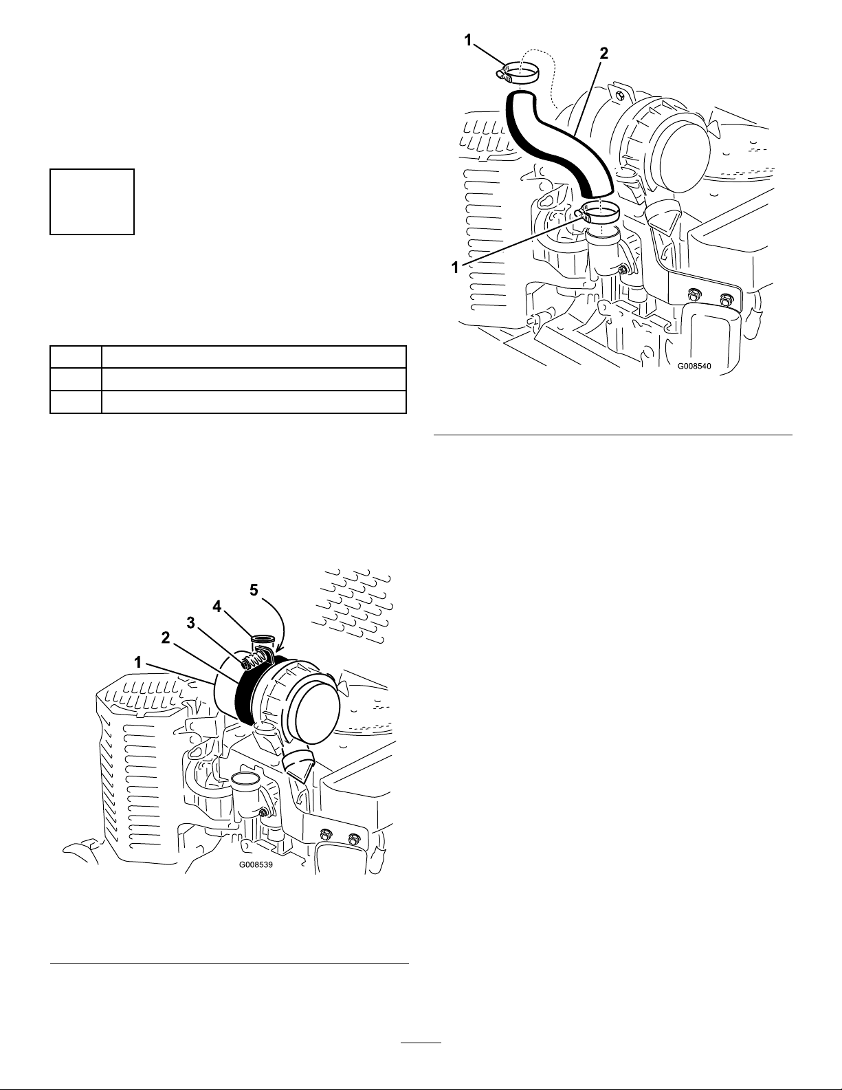
Figure9
1.Hoseclamp2.Largeairhose
Procedure
1.Iftheairintakeportisnotpointingstraightup,
loosentheboltandnutsecuringthecanister
mountingstraps,rotatethecanistersothattheport
isup,andtightentheboltandnuttosecurethe
canister(Figure8).
3.Installtheairhoseontotheintakepipeonthe
carburetorandthelowerportonthecanister
(Figure9).
4.Slidethehoseclampsoverthehoseandlipofthe
intakepipeandlowerportandtightenthemto
securethehose.
5.Placeahoseclampovertheportonthebottomof
theweathercap(Figure10)
Figure8
1.Canister
2.Mountingbracketstrap5.Nut
3.Bolt
2.Slidetwohoseclampsontothelargeairhose
(Figure9).
4.Airintakeport
4
Page 5

Maintenance
1
2
3
3
4
G008661
ReplacingtheAirFilter
ServiceInterval:Every250hours(morefrequentlyif
operatingconditionsareextremely
dustyorsandy).
Note:Servicetheaircleanermorefrequentlyif
operatingconditionsareextremelydustyorsandy.
Important:Topreventenginedamage,always
operatetheenginewiththeairlterandcover
installed.
1.Stoptheengine,removetheignitionkey,andlower
theboom.
2.Releasethelatchesontheaircleanerandpulltheair
cleanercoveroffoftheaircleanerbody(Figure11).
Figure10
1.Weathercap3.Airintakeport
2.Hoseclamp
6.Installtheweathercapontotheairintakeportand
tightenthehoseclamp(Figure10).
Figure11
1.Airlterbody
2.Airlter
3.Latches
4.Aircleanercover
3.Cleantheinsideoftheaircleanercoverwith
compressedair.
4.Gentlyslidetheairlteroutoftheaircleanerbody
(Figure11).Avoidknockingthelterintotheside
ofthebody .
Important:Neverattempttocleantheairlter.
Replaceitafter250hours
5.Carefullyslidetheprimarylterintothecanister
(Figure11).Ensurethatitisfullyseatedbypushing
ontheouterrimofthelterwhileinstallingit.
Important:Donotpressonthesoftinsidearea
ofthelter.
6.Installtheaircleanercoverwiththesidemarked
“UP”facingupandsecurethelatches(Figure11).
5
Page 6

Page 7

Kitdeltrodeairedeserviciopesado
paraZanjadorasTRX
ModelNo.115-4029
LooseParts
Usethechartbelowtoverifythatallpartshavebeenshipped.
FormNo.3360-523RevA
InstallationInstructions
ProcedureDescription
1
2
3
4
Nopartsrequired
Tubodeadmisión1
Junta1
Tubodelrespiradero1
Soportedemontajedelmotor
Conjuntodelcartucho
Pernoconarandelaprensada3
Arandela2
Arandeladefreno
Tuerca2
Tapón1
Mangueradeairegrande1
Abrazadera3
Caperuza
1
Cómoretirarellimpiadorde
Qty.
–
1
1
2
1
3.Cierrelaválvuladecierredelcombustible.
4.Limpietodalasuciedadylosresiduosdelamáquina.
5.Retirelatapadellimpiadordeaire(Figure1).
Retireellimpiadordeaireexistente.
Instaleeltubodeadmisión
Instaleellimpiadordeaire.
Conecteellimpiadordeairealmotor.
Use
aireexistente
NoPartsRequired
Procedure
1.Aparquelamáquinaenunasupercienivelada,pare
elmotor,retirelallavedecontactoybajelaespada.
2.Dejequeelmotorseenfríetotalmenteantesde
continuar.
Sielmotorhaestadoenmarcha,elsilenciador
yelprotectordelsilenciadorestaránmuy
calientesypuedencausarlequemaduras.Este
procedimientorequierequetoqueelprotector
delsilenciador.
Dejequeseenfríentotalmenteelmotoryel
silenciadorantesdeinstalarestekit.
©2008—TheToro®Company
8111LyndaleAvenueSouth
Bloomington,MN55420
Registeratwww.T oro.com.
OriginalInstructions(EN)
ImpresoenEE.UU.
AllRightsReserved
Page 8

Figure1
1.Tapadellimpiadordeaire
6.Retireydesecheeltubodelrespiraderodelmotory
delcarburador(Figure2).
2
Instalacióndeltubode
admisión
Partsneededforthisprocedure:
1Tubodeadmisión
1Junta
1Tubodelrespiradero
Procedure
1.Instaleunjuntanuevayeltubodeadmisiónenel
carburadorusandolastuercasconarandelaprensada
queretiróanteriormente(Figure3),yaprietelas
tuercasconarandelaprensadaa6–7,5Nm(52–69
pulgadas-libra).
Figure2
1.Tuercasconarandela
prensada
7.Retireyguardelas2tuercasconarandelaprensada
quesujetanellimpiadordeaire(Figure2).
8.Retireydesecheellimpiadordeaireylajuntadel
carburador.
2.Tubodelrespiradero
Figure3
1.Espárragodelcarburador3.Tubodeadmisión
2.Junta4.Tuercaconarandela
prensada
2.Instaleelnuevotubodelrespiraderoentreeltubode
admisiónyelmotor(Figure4).
2
Page 9

Figure4
1.Soportedemontajedel
motor
2.Soportedemontajedel
cartucho
3.Pernoconarandela
prensada
4.Arandela
Figure5
5.Arandeladefreno
6.Tuerca
7.Tapón
3
Cómoinstalarellimpiadorde
aire
Partsneededforthisprocedure:
1
Soportedemontajedelmotor
1
Conjuntodelcartucho
3Pernoconarandelaprensada
2Arandela
2
Arandeladefreno
2Tuerca
1Tapón
Procedure
1.Monteelsoportedemontajedelcartuchoenel
soportedemontajedelmotorusando2pernoscon
arandelaprensada,arandelas,arandelasdefrenoy
tuercas,segúnsemuestraenFigure5.
2.Instaleeltapónenelconectordiagnósticodel
cartuchodellimpiadordeaire(Figure5).
3.Retireyguardeelpernodelbordesuperiorinterior
delprotectordelsilenciador,segúnsemuestraen
Figure6.
Figure6
1.Perno2.Protectordelsilenciador
4.Retireelpernoquesujetalaesquinasuperiordela
tapadelaválvulaenelladoizquierdodelamáquina
(Figure7).
3
Page 10

4
Conexióndellimpiadordeaire
almotor
Partsneededforthisprocedure:
1Mangueradeairegrande
3Abrazadera
1
Caperuza
Procedure
1.Silaentradadeairenoestáorientadadirectamente
haciaarriba,aojeelpernoylatuercaquesujetanlas
abrazaderasdemontajedelcartucho,gireelcartucho
hastaquelaentradaquedehaciaarriba,yaprieteel
pernoylatuercaparasujetarelcartucho(Figure8).
Figure7
1.Conjuntodesoportede
montaje
2.Pernoretiradodel
protectordelsilenciador
3.Pernoretiradodelatapa
delaválvula
4.Pernoconarandela
prensada
5.Instaleelconjuntodelsoportedemontajeenel
motorsegúnsemuestraenFigure7,usandoelperno
queretiródelprotectordelsilenciador,elpernoque
retiródelatapadelaválvulayunpernoconarandela
prensadanuevodelkit.
Important:Asegúresedeinsertarelsoporte
demontajeentreelmotoryelprotectordel
silenciadorsegúnsemuestraenFigure7.
Figure8
1.Cartucho
2.Abrazaderadelsoportede
montaje
3.Perno
4.Entradadeaire
5.Tuerca
2.Deslicedosabrazaderassobrelamangueradeaire
grande(Figure9).
4
Page 11

Figure9
1.Abrazadera2.Mangueradeairegrande
3.Instalelamangueradeairesobreeltubodeentrada
delcarburadoryeloricioinferiordelcartucho
(Figure9).
4.Deslicelasabrazaderassobrelamangueraysobre
elbordedeltubodeentradayeloricioinferior,y
apriételasparasujetarlamanguera.
5.Coloqueunaabrazaderasobreeloricioinferiorde
lacaperuza(Figure10).
Figure10
1.Caperuza
2.Abrazadera
3.Entradadeaire
6.Instalelacaperuzasobrelaentradadeaireyapriete
laabrazadera(Figure10).
5
Page 12

Maintenance
1
2
3
3
4
G008661
Cambiodelltrodeaire
ServiceInterval:Every250hours(Conmásfrecuencia
silazonadetrabajotienemucho
polvooarena).
Note:Reviseellimpiadordeaireconmayorfrecuencia
encondicionesdetrabajodemuchopolvooarena.
Important:Paraevitardañarelmotor,nohaga
funcionarnuncaelmotorsinqueesténinstalados
elltrodeaireylatapa.
1.Pareelmotor,retirelallavedecontactoybajela
espada.
2.Abraloscierresdellimpiadordeaireytiredelatapa
dellimpiadordeaireparasepararladelacarcasadel
limpiadordeaire(Figure11).
Figure11
1.Carcasadelltrodeaire3.Cierres
2.Filtrodeaire4.Tapadellimpiadordeaire
3.Limpieelinteriordelatapadellimpiadordeaire
conairecomprimido.
4.Extraigaconcuidadoelltrodeairedelacarcasadel
limpiadordeaire(Figure11).Evitegolpearelltro
contraelladodelacarcasa.
Important:Nointentenuncalimpiarelltrode
aire.Cámbielocada250horas
5.Desliceconcuidadoelltroprimariosobreel
cartucho(Figure11).Asegúresedequeestábien
asentadoempujandosobreelbordeexteriordelltro
mientrasloinstala.
Important:Noempujesobrelazonablanda
interiordelltro.
6.Instalelatapadellimpiadordeaireconelladoque
llevalapalabra"UP"haciaarriba,yjeloscierres
(Figure11).
6
 Loading...