

Page 1

OilCoolerKit
2007andBeforeKubota-PoweredZMasterRidingMower
ModelNo.115–3565
Note:Wheninstallingthiskit,itisanidealtimeto
changethehydraulicoillter.ContactanAuthorized
ServiceDealerforthecorrectlter.
Hydraulicuidescapingunderpressurecan
penetrateskinandcauseinjury.
•Ifhydraulicuidisinjectedintotheskin
itmustbesurgicallyremovedwithinafew
hoursbyadoctorfamiliarwiththistypeof
injury.Gangrenemayresultifthisisnot
done.
•Keepbodyandhandsawayfrompinhole
leaksornozzlesthatejecthighpressure
hydraulicuid.
FormNo.3359-917RevA
InstallationInstructions
•Usecardboardorpapertondhydraulic
leaks.
•Safelyrelieveallpressureinthehydraulic
systembeforeperforminganyworkonthe
hydraulicsystem.
•Makesureallhydraulicuidhosesand
linesareingoodconditionandallhydraulic
connectionsandttingsaretightbefore
applyingpressuretohydraulicsystem.
LooseParts
Usethechartbelowtoverifythatallpartshavebeenshipped.
ProcedureDescription
Oilcooler
Hose2
1
2
3
Hoseclamp2
Hosesleeve1
Elbowttings
Bolt(1/4x1–1/4inches)
Locknut(1/4inch)
Plastictie1
Actuatorseal2
Externallockwasher2
Qty.
Use
1
Removethehydrauliccoolerand
drainingthehydraulicoil.
2
1
1
Installtheelbowttingsandroutethe
hoses.
Installtheactuatorseals.
4
©2008—TheT oro®Company
8111LyndaleAvenueSouth
Bloomington,MN55420
Nopartsrequired
Registeratwww.Toro.com.
–
Verifytheconnections.
OriginalInstructions(EN)
PrintedintheUSA.
AllRightsReserved
Page 2

1
ReplacingtheHydraulic
CoolerandDrainingthe
HydraulicOil
Partsneededforthisprocedure:
1
Oilcooler
2Hose
2Hoseclamp
1Hosesleeve
Procedure
Important:Allowthehydraulicoiltocoolbefore
installingthiskit.
1.DisengagethePTO,movethemotioncontrollevers
totheneutrallockedpositionandsettheparking
brake.
Figure2
7.Loosentheboltsholdingtheenginestrapstothe
sideofthemachine(Figure3).
8.Removethe4nutsandboltsholdingtheoilcooler
shieldtotherearframe(Figure3).Savethesenuts
andbolts.
2.Stoptheengine,removethekey,andwaitforall
movingpartstostopbeforeleavingtheoperating
position.
3.Allowtheenginetocoolbeforeinstallingthiskit.
4.Thoroughlywashthemachinetoavoidgettingany
debrisintothehydraulicsystem.
5.Jackuptherearofthemachineandsupportitwith
jackstands(Figure1).
Figure1
Figure3
1.Bolts
2.Washers5.Loosenenginestrapbolts
3.Oilcoolershield
9.Removethe4nutsandboltsholdingtheoilcooler
andremovetheoilcooler(Figure4).Savethesenuts
andbolts.
4.Oilcooler
6.Removetheleftrearwheel(Figure2).
2
Page 3

Figure4
1.Nuts3.Washers
2.Oilcooler
4.Bolts
10.Placealargepanundertheoilcoolertocollectthe
hydraulicoil.
11.Removethehosesfromtheoilcooleranddrainthe
hydraulicoilintothepan.
Note:Thisisanidealtimetochangethehydraulic
oillter.ContactanAuthorizedServiceDealerfor
thecorrectlter.
12.Placetheoilpanunderthehydraulicoillter.
Removethehydraulicoillterandallowalloilto
drainintothepan.
13.Removethe4R-clampsinstalledontheoldoil
coolerandinstallthemontothenewoilcooler.
Note:Thenewhosesarethesamelengthanditis
notimportantwhichendorsidetheyareinstalledto
theoilcooler.
14.Installthenewhosestothenewoilcoolerwith2
hoseclamps(Figure5).
Figure5
1.Hoseclamp5.Previouslyremovedbolt
2.Oilcooler
3.Hoses7.Previouslyremovedoil
4.NewR-clamp
6.Previouslyremovednut
coolerR-clamp
15.Installtheoilcoolershieldtotherearframewiththe
4nutsandboltspreviouslyremoved(Figure3).
16.Tightentheboltsfortheenginestrapsonthesideof
themachine(Figure3).
17.Installtheoilcoolershieldwiththe4nutsandbolts
previouslyremoved(Figure4).
18.Installanewhydrauliclter.
3
Page 4

3.Removetheexistinghoseandleftsideelbowtting
fromthebottomofthehydraulictank.
2
InstallingtheElbowFittings
andRoutingtheHoses
Partsneededforthisprocedure:
2
Elbowttings
1
Bolt(1/4x1–1/4inches)
1
Locknut(1/4inch)
1Plastictie
Procedure
Note:Thenewhosesarethesamelengthanditisnot
importantwhichhoseisinstalledtotheelbowinthe
tankorthepump.
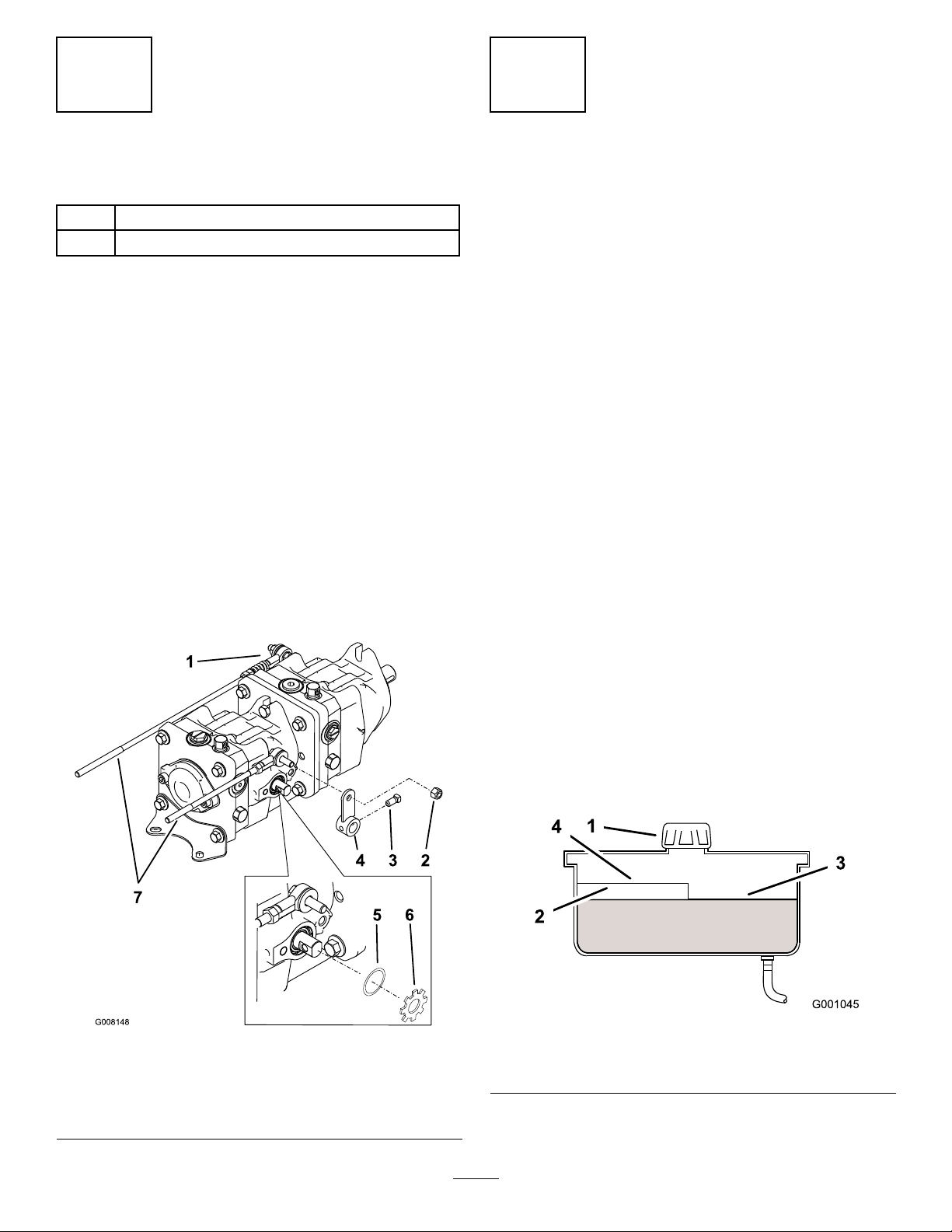
1.Removetheexistinghoseandelbowontheleftside
ofthebackpump(Figure6).
2.Installthenewelbowttingintotheleftsideof
thebackpump(Figure6).RefertoFigureforthe
correctangle.
4.Installthenewleftsideelbowttingtothebottom
ofthehydraulicoiltank(Figure7).RefertoFigure
forthecorrectangle.
Figure7
1.Hydraulicoiltank
2.Hoseclamp5.60degreeangle
3.Elbowttingat60degree
angle
4.ElbowttingwithO-ring
1.Leftsideofpumps
2.Hoseclamp
3.Elbowtting
5.RoutethehosesthroughthenewR-clampandalong
thesideofthemachine(Figure9).
6.Installthesleeveontothehosesandroutethrough
thepumpplate(Figure8andFigure9).Makesure
thesleeveisinstallintotheholeinthepumpplate.
7.Securethehosestothesideofthemachinewitha
plastictie(Figure8).
Figure6
4.90degreeangle
5.Elbowttingshownat90
degreeangle
4
Page 5

Figure8
1.Leftsideofpumps
2.ElbowttingwithO-ring
3.Hoseclamp7.Hydraulicoiltank
4.Hose8.Hosesleeve
5.Plastictie
6.Pumpplate
Figure9
1.Hydraulicoiltank3.Pumpplate5.Hose
2.Pumps4.Hosesleeveinstalled
throughpumpplate
7.Oilcooler
6.R-clamp
5
Page 6
3
4
InstallingtheActuatorSeals
Partsneededforthisprocedure:
2Actuatorseal
2Externallockwasher
Procedure
1.Loosenthesetscrewintheactuatorarm(Figure10).
2.Removethenutholdingtheactuatortotherod.
3.Removetheactuatorarmfromthepump.
4.Removetheexternallockwasherandsealfromthe
pump(Figure10).
5.Installthenewsealandexternallockwashertothe
pump.
6.Installtheactuatorarmwiththesetscrew .Use
threadlockeronthesetscrewandtorqueitto145
±20in-lbs.
7.Installtheactuatorarmtotherodwiththenut
(Figure10).
8.Repeatthisprocedurefortheoppositeside.
VerifyingtheConnections
NoPartsRequired
Procedure
FluidType:Mobil115W -50syntheticmotoroilor
equivalentsyntheticoil.
HydraulicSystemOilCapacity:132ounces(3.9l)
Important:Useoilspeciedorequivalent.Other
uidscouldcausesystemdamage.
1.Removethecapfromthehydraulicoiltank
(Figure11).
2.Addnewuidtothereservoiruntilitreachesthe
coldlevelofthebafe.
3.Ensuretherearenoleaksatthefuelhose
connections.
4.Starttheengineandensuretherearenoleaks.
5.Runthemachineatlowidlefor15minutestoallow
anyairtopurgeoutofthesystemandwarmtheuid.
6.Rechecktheuidlevelwhiletheuidiswarm.The
uidshouldbebetweencoldandhot.
Figure10
1.Rightsideactuator
2.Nut6.Externallockwasher
3.Setscrew
4.Actuatorarm
5.Seal
7.Rod
7.Ifrequired,adduidtothehydraulictank.
Note:Theuidlevelshouldbetothetopof
thecoldlevelofthebafe,whentheuidiscold
(Figure11).
8.Installcaponllerneck.
Figure11
1.Cap3.Colduidlevel-full
2.Bafe4.Hotuidlevel-full
6
Page 7

Notes:
7
Page 8

 Loading...