

Page 1
Bio-DieselFuelFilterKit
Daihatsu-PoweredRidingMowers
ModelNo.115–3550
Afterthiskitisinstalled,thismachinecanusea
biodieselblendedfuelofuptoB20(20%biodiesel,80%
petrodiesel).Thepetrodieselportionshouldbelowor
ultralowsulfur.
FormNo.3360-692RevA
InstallationInstructions
Incertainconditions,fuelisextremely
ammableandhighlyexplosive.Areor
explosionfromfuelcanburnyouandothers
andcandamageproperty.
Fuelisharmfulorfatalifswallowed.Long-term
exposuretovaporscancauseseriousinjuryand
illness.
•Avoidprolongedbreathingofvapors.
•Keepfaceawayfromnozzleandgastankor
conditioneropening.
•Keepfuelawayfromeyesandskin.
LooseParts
Usethechartbelowtoverifythatallpartshavebeenshipped.
ProcedureDescription
1
2
3
4
Nopartsrequired
Mountingplate1
Locknut(1/4inch)
Fuellterclamp
Bolt(5/16x1-3/4inches)
Bolt(5/16x3/4inch)
Locknut(5/16inch)
Waterseparator1
Hose1
Hoseclamp3
J-clamp1
Plastictie2
Lowsulfurdecal
Fuelcap2
Dieseldecal1
•Wipeupanyfuelthatspills.
•Neverllthefueltankinsideanenclosed
trailer.
•Neversmokewhenhandlingfuel,andstay
awayfromanopenameorwherefuel
fumesmaybeignitedbyaspark.
Qty.
–
1
1
1
1
2
2
Removetheexistingwaterseparator
Installthewaterseparator.
Installingandconnectingthefuelhoses.
Installthedecalsandfuelcaps.
Use
5
©2008—TheToro®Company
8111LyndaleAvenueSouth
Bloomington,MN55420
Nopartsrequired
Registeratwww.T oro.com.
–
Verifytheconnections.
OriginalInstructions(EN)
PrintedintheUSA.
AllRightsReserved
Page 2
1
RemovingtheExistingWater
Separator
NoPartsRequired
Procedure
Important:Allowtheenginetocoolbefore
installingthiskit.
1.Drivethemachinetoawellventilatedareaaway
fromanopenameorwherefuelfumesmaybe
ignitedbyaspark.
2.Disengagethepowertakeoff(PTO)andsetthe
parkingbrake.
3.Turnofftheengine,removethekey,andwaitforall
movingpartstostopbeforeleavingtheoperating
position.
4.Disconnectthenegativebatterycablefromthe
battery.
5.Allowtheenginetocoolbeforeinstallingthiskit.
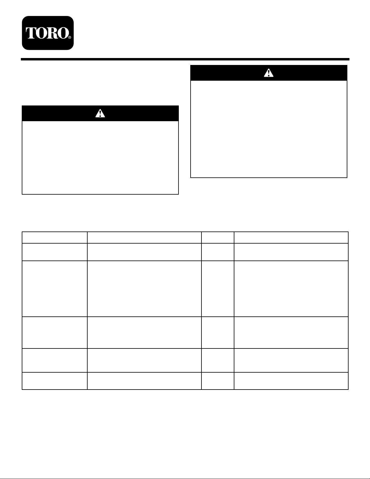
6.Tilttheseatforwardandremovethefrontengine
panel(Figure1).
7.Closethefuelselectorvalve.
1.Fuelhosefromthe
separatortotheengine
(makenotewherethe
connectionisonthe
engine)
2.Hosefromfuelselector
valve
2
InstallingtheWaterSeparator
Partsneededforthisprocedure:
Figure2
3.Existingwaterseparator
4.Fuelselectorvalve
Figure1
1.Knob2.Frontenginepanel
8.Locatethehosebetweenthewaterseparatorandthe
fuelselectorvalve.Removethefuelhosefromthe
fuelselectorvalve(Figure2).
9.Locatethehosebetweenthewaterseparatorandthe
fuelselectorvalve.Removethefuelhosefromthe
theengine(Figure2).Rememberthelocationwhere
thefuelhosewasconnectedtotheengine.
10.Removetheexistingwaterseparatorfromthe
machine.
1Mountingplate
1
Locknut(1/4inch)
1
Fuellterclamp
1
Bolt(5/16x1-3/4inches)
1
Bolt(5/16x3/4inch)
2
Locknut(5/16inch)
1Waterseparator
Procedure
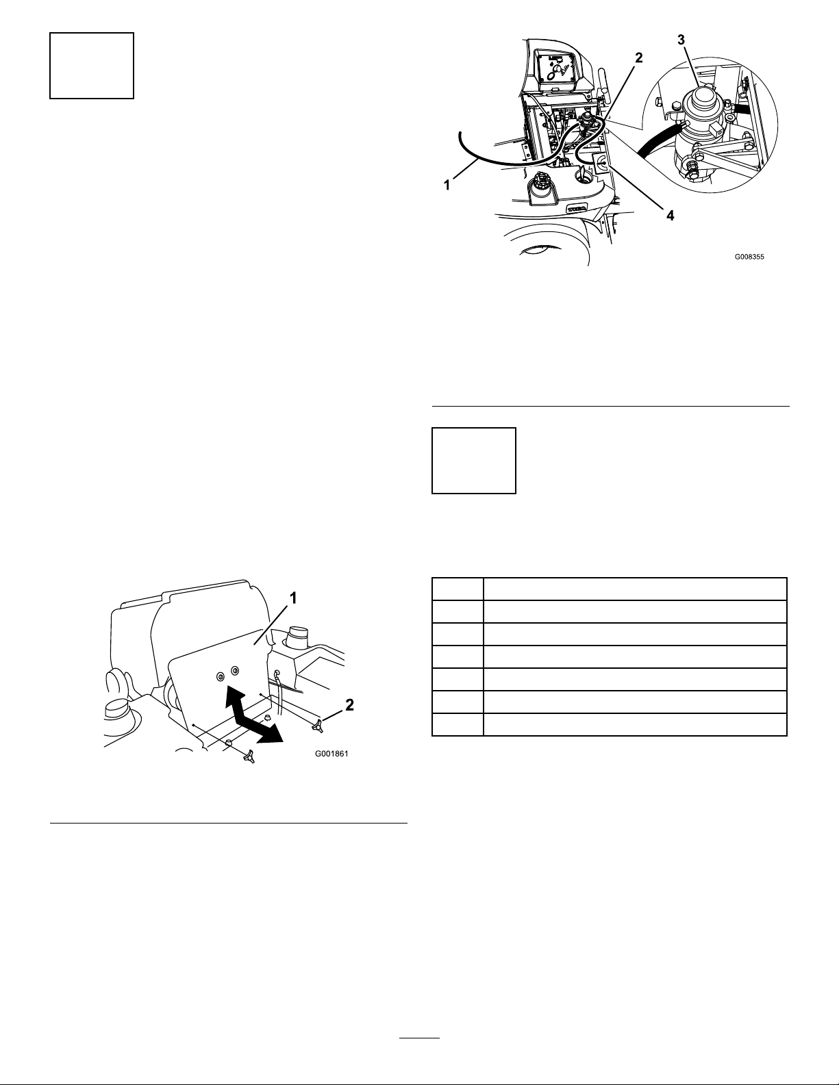
1.Removetheexistinghardwarefromtheenginestrap
(Figure3).
2.Installthemountingbrackettotheenginestrapwith
thepreviouslyremovedhardware(Figure3).
3.Installthewaterseparatorintothefuellterclamp
andinstallittothemountingbracketwithabolt
(5/16x1-3/4inches),abolt(5/16x3/4inch),and
2locknuts(5/16inch)(Figure3).
2
Page 3
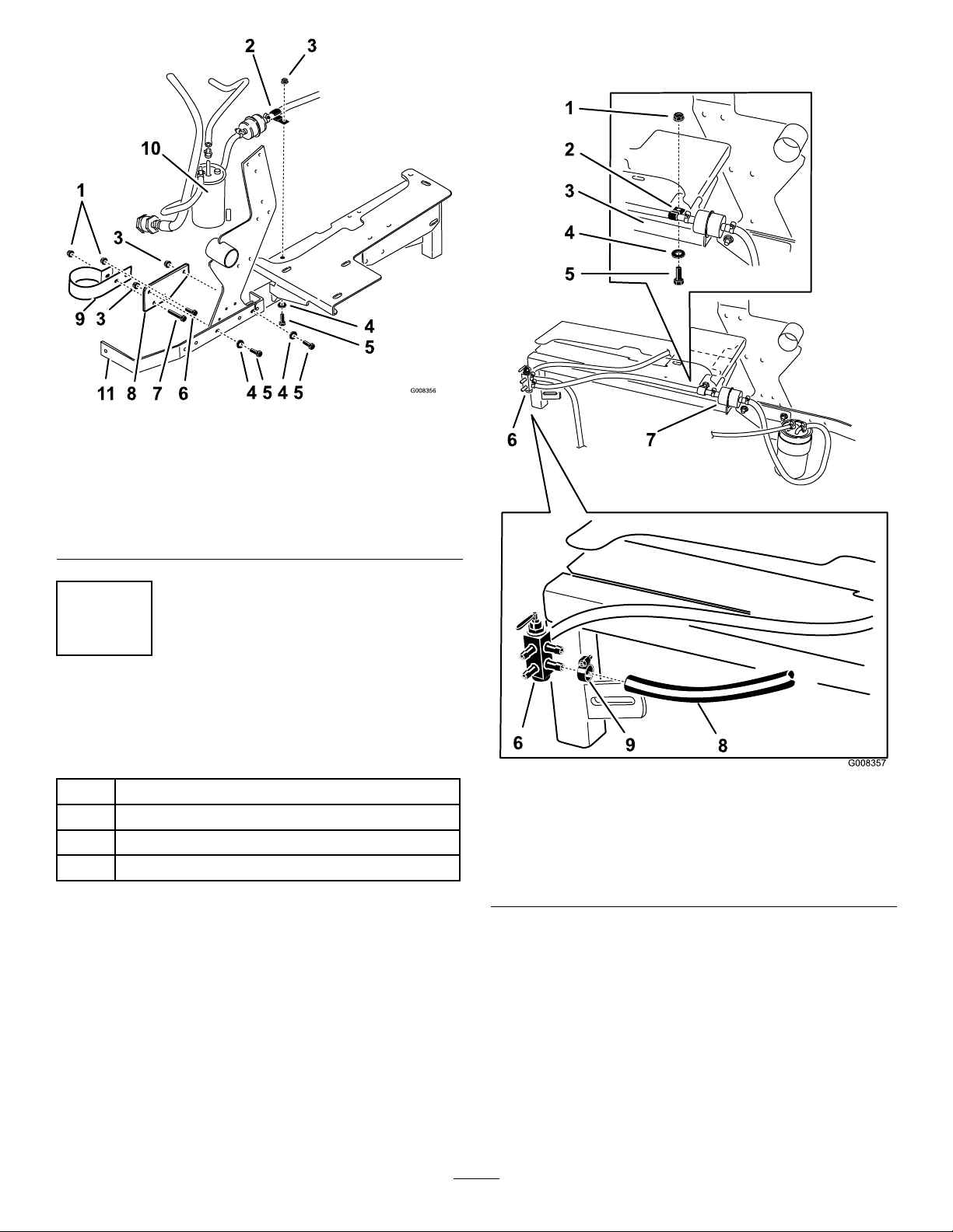
Figure3
1.Locknut(5/16inch)7.Bolt(5/16x1-3/4inches)
2.J-clamp8.Mountingplate
3.Existinglocknut
4.Existingwasher10.Waterseparator
5.Existingbolt11.Enginestrap
6.Bolt(5/16x3/4inch)
9.Fuellterbracket
5.Installtheplastictiestosecurethehosesfrom
touchinganyhotpartsofthemachine.
3
InstallingandConnectingthe
FuelHoses
Partsneededforthisprocedure:
1Hose
3Hoseclamp
1J-clamp
2Plastictie
Procedure
1.Routethefuellterandfuelhosetowardsthefuel
selectorvalve.Makesurenopartsorhosesare
touchingthemachineinareasthatwillgethot.
2.RemovetheexistinghardwareandintalltheJ-clamp
totheengineframe(Figure3andFigure4).
3.Installthefuelhoseconnectedtothefuellterinto
theJ-clamp(Figure4).
Figure4
1.Existinglocknut6.Fuelselectorvalve
2.J-clamp
3.Engineframe
4.Existingwasher9.Hoseclamp
5.Existingbolt
7.Fuellter
8.Fuelhose
4.Installthenewfuelhoseontofuelselectorvalvewith
ahoseclamp(Figure4).
3
Page 4

6.Installthenewfuelhosetothewaterseparatorand
G008099
1
2
G008999
1
G008998
1
totheenginefuelconnectionwith2hoseclamps
(Figure5).Theconnectiontotheengineisthe
samepositionasthefuelhosethatwaspreviously
removed.
1.Enginehood
Figure6
2.Lowsulfurdecal
Figure5
1.Hoseclamp3.Waterseparator
2.Newfuelhose,connect
thisendtotheenginefuel
intake
4
InstallingtheDecalsandFuel
Caps
Partsneededforthisprocedure:
2
Lowsulfurdecal
2Fuelcap
1Dieseldecal
4.Cleantheexistingfrontdecalandtheareaaroundit
andletitdry(Figure7).
5.Installthenewdieseldecalovertheexistingone.See
Figure7.
Figure7
1.Dieseldecal
6.Removebothexistingfuelcapsandreplacethem
withthenewfuelcaps(Figure8).
Procedure
1.Lowertheenginehood.
2.Removetheexistingdecaloneachside.
3.Installalowsulfurdecaloneachsideoftheengine
hood.SeeFigure6forthecorrectposition.
Figure8
1.Newfuelcap
4
Page 5

Operation
5
VerifyingtheConnections
NoPartsRequired
Procedure
1.Openthefuelselectorvalve.
2.Openthewaterseparatordrainvalveuntilfuelstarts
todrainoutandclosethevalve(Figure9).
3.Ensuretherearenoleaksatthefuelhose
connections.
4.Installthenegativebatterycableontothebattery.
5.Starttheengineandensuretherearenoleaks.
AddingFuel
Afterthiskitisinstalled,thismachinecanusea
biodieselblendedfuelofuptoB20(20%biodiesel,
80%petrodiesel).Thepetrodieselportionshouldbe
loworultralowsulfur.
Observethefollowingprecautions:
•Thebiodieselportionofthefuelmeetspecication
ASTMD6751orEN14214.
•TheblendedfuelcompositionshouldmeetASTM
D975orEN590.
•Paintedsurfacesmaybedamagedbybiodiesel
blends.
•UseB5(biodieselcontendof5%)orlesserblend
incoldweather.
•Monitorseals,hoses,gasketsincontactwithfuelas
theymaybedegradeovertime.
•Fuellterpluggingmaybeexpectedforatimeafter
convertingtobiodieselblends.
1.Waterseparator
2.Drainvalve
Figure9
3.Rightsideofmachine
•Contactyourdistributorifyouwishformore
informationonbiodiesel.
Purchasefuelinquantitiesthatcanbeusedwithin
30daystoensurefuelfreshness.
Usesummergradedieselfuel(No.2-D)attemperatures
above20°F(-7°C)andwintergradedieselfuel(No.
1-DorNo.1-D/2-Dblend)below20°F(-7°C).Useof
wintergradedieselfuelatlowertemperaturesprovides
lowerashpointandpourpointcharacteristics,
thereforeeasingstartabilityandlesseningchances
ofchemicalseparationofthefuelduetolower
temperatures(waxappearance,whichmaypluglters).
Useofsummergradedieselfuelabove20°F(-7°C)will
contributetowardlongerlifeofthepumpcomponents.
Important:Donotusekeroseneorgasoline
insteadofdieselfuel.Failuretoobservethis
cautionwilldamagetheengine.
5
Page 6

Incertainconditions,fuelisextremely
ammableandhighlyexplosive.Areor
explosionfromfuelcanburnyouandothers
andcandamageproperty.
•Fillthefueltankoutdoors,inanopenarea,
whentheengineiscold.Wipeupanyfuel
thatspills.
•Neverllthefueltankinsideanenclosed
trailer.
Fuelisharmfulorfatalifswallowed.Long-term
exposuretovaporscancauseseriousinjuryand
illness.
•Avoidprolongedbreathingofvapors.
•Keepfaceawayfromnozzleandgastankor
conditioneropening.
•Keepgasawayfromeyesandskin.
•Donotllthefueltankcompletelyfull.Add
fueltothefueltankuntilthelevelis1/4to
1/2inch(6to13mm)belowthebottomof
thellerneck.Thisemptyspaceinthetank
allowsfueltoexpand.
•Neversmokewhenhandlingfuel,andstay
awayfromanopenameorwherefuel
fumesmaybeignitedbyaspark.
•Storefuelinanapprovedcontainerandkeep
itoutofthereachofchildren.Neverbuy
morethana30-daysupplyoffuel.
•Alwaysplacefuelcontainersontheground
awayfromyourvehiclebeforelling.
•Donotllfuelcontainersinsideavehicle
oronatruckortrailerbedbecauseinterior
carpetsorplastictruckbedlinersmay
insulatethecontainerandslowthelossof
anystaticcharge.
•Whenpractical,removegas-powered
equipmentfromthetruckortrailerand
refueltheequipmentwithitswheelsonthe
ground.
FillingtheFuelTank
1.Shuttheengineoffandsettheparkingbrake.
2.Cleanaroundeachfueltankcapandremovethe
cap.Addfueltobothfueltanks,untilthelevelis
1/4to1/2inch(6to13mm)belowthebottomof
thellerneck.Thisspaceinthetankallowsthefuel
toexpand.Donotllthefueltankscompletelyfull.
3.Installfueltankcapssecurely.Wipeupanyfuelthat
mayhavespilled.
4.Ifpossible,llthefueltankaftereachuse.Thiswill
minimizepossiblebuildupofcondensationinside
thefueltank.
•Ifthisisnotpossible,thenrefuelsuch
equipmentonatruckortrailerfroma
portablecontainer,ratherthanfromafuel
dispensernozzle.
•Ifafueldispensernozzlemustbeused,keep
thenozzleincontactwiththerimofthefuel
tankorcontaineropeningatalltimesuntil
fuelingiscomplete.
6
Page 7
Maintenance
ServicingtheFuelFilter
ChangingtheFuelFilter
ServiceInterval:Every400hours/Yearly(whichever
comesrst)(moreoftenindirtyor
dustyconditions).
DrainingtheWaterSeparator
ServiceInterval:Every40hours
1.Positionthemachineonalevelsurface.
2.DisengagethePTO,movethemotioncontrollevers
totheneutrallockedpositionandsettheparking
brake.
3.Stoptheengine,removethekey ,andwaitforall
movingpartstostopbeforeleavingtheoperating
position.
4.Locatethewaterseparatoratthebackleftofthe
machine.
5.Placeadrainpanbelowthewaterseparator.
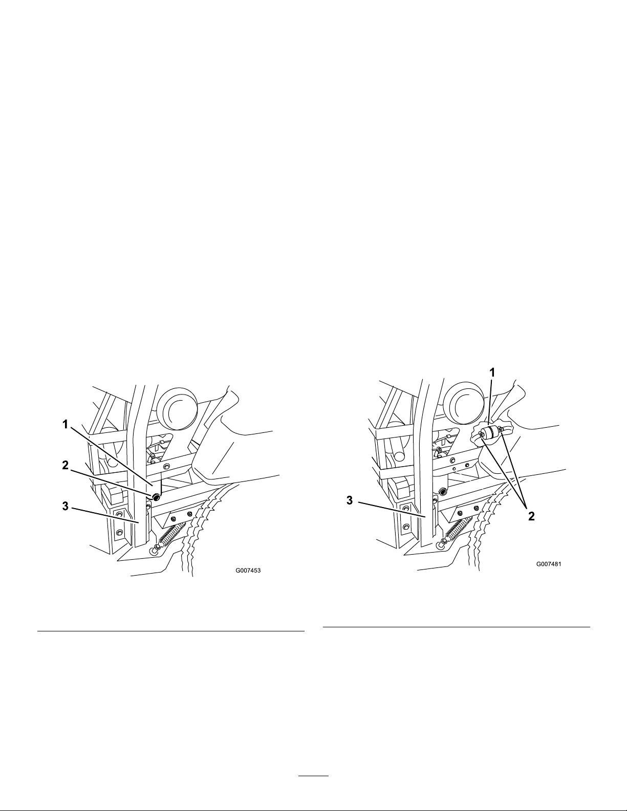
6.Openthedrainvalveonthewaterseparator
approximatelyoneturntoallowwaterandother
contaminatestodrain(Figure10).
7.Closethedrainvalvewhenonlydieselfuelcomes
out(Figure10).
Neverinstalladirtyfuellterifitisremovedfromthe
fuelline.
1.Allowthemachinetocooldown.
2.DisengagethePTO,movethemotioncontrollevers
totheneutrallockedpositionandsettheparking
brake.
3.Stoptheengine,removethekey ,andwaitforall
movingpartstostopbeforeleavingtheoperating
position.
4.Closethefuelshut-offvalve.
5.Loosenthetwohoseclampsanddisconnectthefuel
linesfromthefuellter(Figure11).
6.Installanewlter.Connectthefuellinestothefuel
lterandinstallthetwohoseclamps.
7.Openthefuelshut-offvalve.
8.Starttheengineandcheckforleaks.
1.Waterseparator
2.Drainvalve
Figure10
3.Rightsideofmachine
Figure11
1.Fuellter3.Rightsideofmachine
2.Hoseclamps
7
Page 8

 Loading...