

Page 1
PumpBeltGuideKit
Daihatsu-poweredZMaster
ModelNo.114–8244
Installation
LooseParts
Usethechartbelowtoverifythatallpartshavebeenshipped.
FormNo.3358-746RevA
®
RidingMower
InstallationInstructions
ProcedureDescription
Idlerpulleybeltguide1
Curvedwasher
1
2
Belt1
Spring
Beltguide2
Bolt(1/2x1-1/2inches)
1
InstallingtheIdlerPulleyBelt
Guide,SpringandBelt
Partsneededforthisprocedure:
1Idlerpulleybeltguide
1
Curvedwasher
1Belt
1
Spring
Qty.
1
1
2
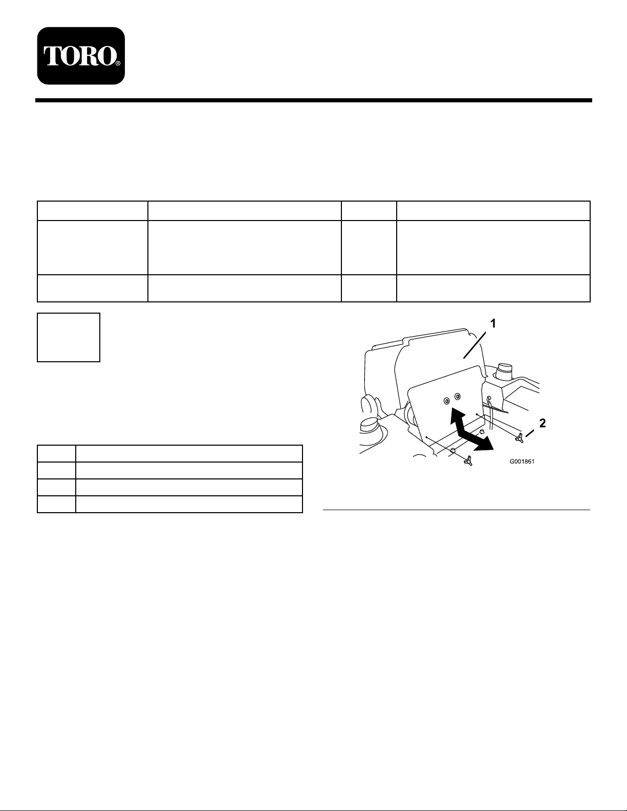
1.Frontenginepanel2.Knob
Installtheidlerpulleybeltguide,spring
andbelt.
Installthepumppulleybeltguides.
Figure1
Use
Procedure
1.DisengagethePTO,movethemotioncontrollevers
totheneutrallockedpositionandsettheparking
brake.
2.Stoptheengine,removethekey,andwaitforall
movingpartstostopbeforeleavingtheoperating
position.
3.Allowtheenginetocooldown.
4.Tilttheseatforwardandremovethefrontengine
panel(Figure1).
©2007—TheToro®Company
8111LyndaleAvenueSouth
Bloomington,MN55420
Registeratwww.T oro.com.
5.Removetheknobsandthelowerenginepanelfrom
themachine.
6.Toreplacethebelt,pullthespringloadedidlerdown
andremovethetractionbeltfromtheengineand
hydropumppulleys(Figure2).
7.Removetheexistingidlerspringandinstallthenew
spring(Figure3andFigure4).
8.Installthenewbeltaroundtheengineandhydro
pumppulleys(Figure2).
9.Pullthespringloadedidlerdownandinstallthe
belt.Releasethepressureonthespringloadedidler
(Figure2).
OriginalInstructions(EN)
PrintedintheUSA.
AllRightsReserved
Page 2
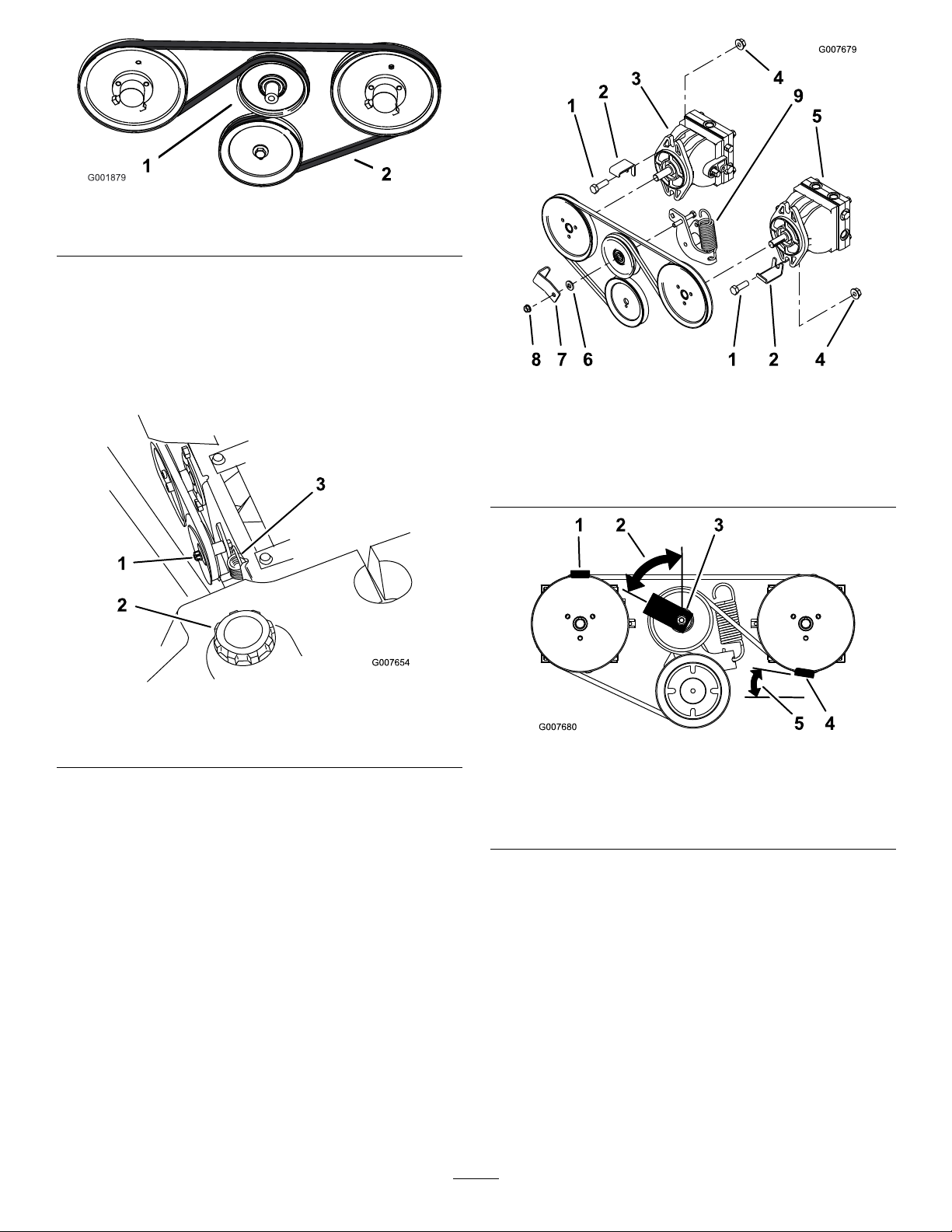
Figure2
1.Springloadedidlerpulley
2.Pumpdrivebelt
10.Locatetheidlerpulleyandremovethenutthatis
locateontheengineside(Figure3).
11.Installtheidlerpulleybeltguideandcurvedwasher
withthepreviouslyremovednut(Figure3and
Figure4).Makesurethepulleybeltguideisinstalled
ata62degreeangleasshownin(Figure5).
Figure4
1.Bolt(1/2x1-1/2inches)6.Curvedwasher
2.Beltguide7.Idlerpulleybeltguide
3.Leftsidepump
4.Existingnut
5.Rightsidepump
8.Existingnut
9.Spring
1.Idlerpulleynut
2.Rightsidefueltank
Figure3
3.Spring
Figure5
1.Beltguideinstalledforthe
leftsidepulley
2.62degreeangle5.9degreeangle
3.Idlerpulleybeltguide
4.Beltguideinstallforthe
rightsidepulley
2
Page 3

2
InstallingthePumpPulleyBelt
Guides
Partsneededforthisprocedure:
2Beltguide
2
Bolt(1/2x1-1/2inches)
Procedure
Note:Determinetheleftandrightsidesofthemachine
fromthenormaloperatingposition.
1.Removethenutandboltholdingtherightsidepump
totheframe.Savethenut.
2.Installthebeltguidewithanewbolt(1/2x1-1/2
inches)andnutpreviouslyremoved(Figure6and
Figure8).Makesurethepulleybeltguideisinstalled
attheangleasshowninFigure9.
1.Nutandbolttoremove
Figure7
2.Rightsidefueltank
Figure6
Bottomviewshown
1.Nutandbolttoremove3.Rightsidetire
2.Engineoilpan
3.Removethenutandboltholdingtheleftsidepump
totheframe.Savethenut.
4.Installthebeltguidewithanewbolt(1/2x1-1/2
inches)andnutpreviouslyremoved(Figure7and
Figure8).Makesurethepulleybeltguideisinstalled
ata62degreeangleasshowninFigure9.
Figure8
1.Bolt(1/2x1-1/2inches)
2.Beltguide
3.Leftsidepump
4.Existingnut8.Existingnut
3
5.Rightsidepump
6.Curvedwasher
7.Idlerpulleybeltguide
Page 4

Figure9
1.Beltguideinstalledforthe
leftsidepulley
2.62degreeangle5.9degreeangle
3.Idlerpulleybeltguide
4.Beltguideinstallforthe
rightsidepulley
5.Installthelowerenginepanelandtheknobs.
6.Installthefrontenginepanel(Figure1).
4
 Loading...