

Page 1

ReplacementOguraClutchKit
For2006through2007Kubota-PoweredZMasterRidingMowers
ModelNo.114–8150
LooseParts
Usethechartbelowtoverifythatallpartshavebeenshipped.
FormNo.3360-571RevA
InstallationInstructions
ProcedureDescription
1
2
Nopartsrequired
Clutchadapter
Key1
Clutch
Retainer1
Flatwasher(.469x.922inch)
Curvedwasher(7/16inch)
Locknut(5/16inch)
Carriagebolt(5/16x1inch)
Spacer
Clutchstop
Flatwasher(.344x.688inch)
Bolt(5/16x1inch)
Locknut(5/16inch)
1
RemovingtheExistingClutch
Qty.
Use
–
1
1
1
2
3
1
3
1
4
1
3
Removetheexistingclutch
Installthenewclutch.
NoPartsRequired
Procedure
Important:Allowtheenginetocoolbefore
installingthiskit.
1.Disengagethepowertakeoff(PTO)andsetthe
parkingbrake.
2.Turnofftheengine,removethekey,andwaitforall
movingpartstostopbeforeleavingtheoperating
position.
3.Allowtheenginetocoolbeforeinstallingthiskit.
4.Tilttheseatforwardandremovethefrontengine
panel(Figure1).
©2008—TheT oro®Company
8111LyndaleAvenueSouth
Bloomington,MN55420
Registeratwww.Toro.com.
Figure1
1.Frontenginepanel2.Knob
5.Removethespringfromtheidlerarm(Figure2).
6.Removetheclutchstopbracketfromthemachine.
Theholesfortheclutchstopwillbeusedforthe
newclutch(Figure2).
7.RemovethePTOdrivebeltfromtheclutch
(Figure2).
OriginalInstructions(EN)
PrintedintheUSA.
AllRightsReserved
Page 2
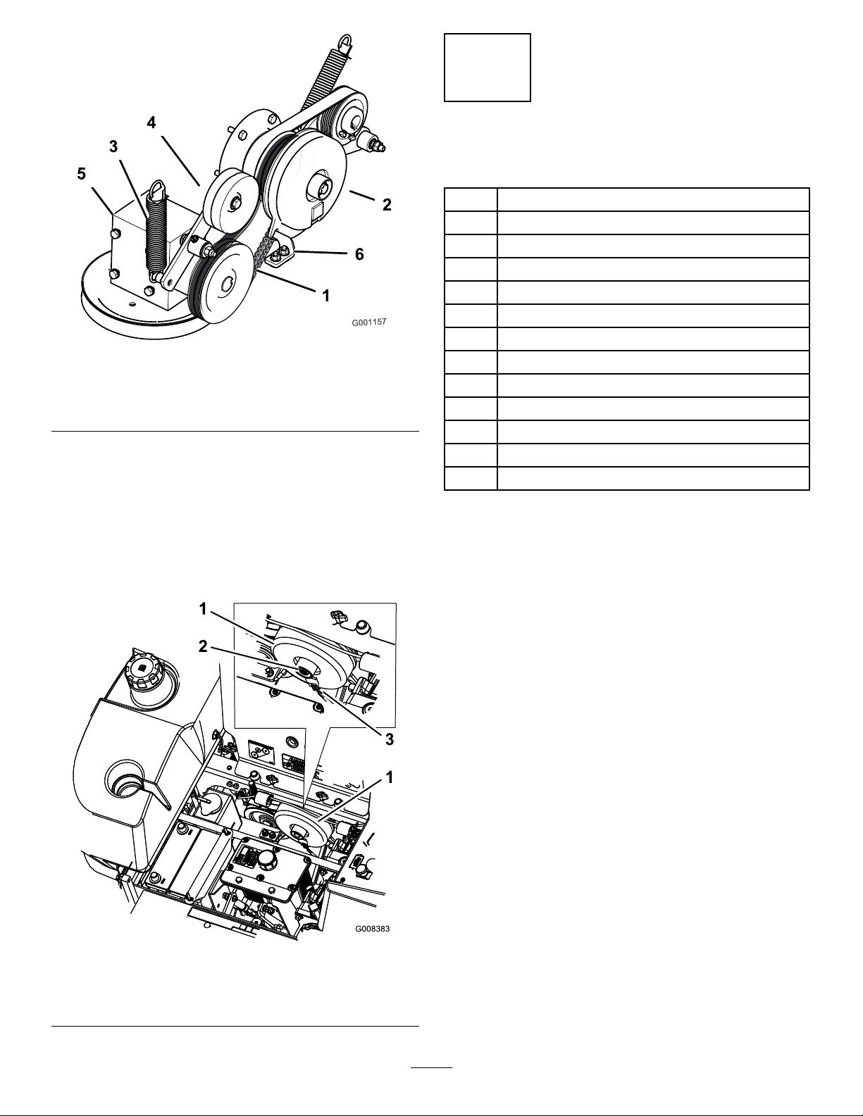
Figure2
1.PTOdrivebelt4.Springloadedidlerpulley
2.Clutch5.Gearbox
3.Spring6.Clutchstopbracket
8.Unplugtheelectricalconnectionattheclutch
(Figure3).
9.Toremovetheclutchbolt,useawrenchtoholdthe
enginecrankshaftattherearoftheengine.
10.Removetheboltinthecenteroftheclutchandslide
theclutchofftheengineshaft(Figure3).Savethe
boltforinstallingthenewclutch.
2
InstallingtheNewClutch
Partsneededforthisprocedure:
1
Clutchadapter
1Key
1
Clutch
1Retainer
1
Flatwasher(.469x.922inch)
2
Curvedwasher(7/16inch)
3
Locknut(5/16inch)
1
Carriagebolt(5/16x1inch)
3
Spacer
1
Clutchstop
4
Flatwasher(.344x.688inch)
1
Bolt(5/16x1inch)
3
Locknut(5/16inch)
Procedure
1.Installthenewclutchstoptotheclutchwithabolt
(5/16x1inch),2atwashers(.344x.688inch),a
spacerandalocknut(5/16inch)(Figure4).
1.Clutch
2.Removethecenterbolt
2.Installtheclutchadapterontothestubshaft
(Figure4).Ensureitisinstalledasshown.
3.Installthekeyontothestubshaftandalignthekey
withtheclutch.Slidetheclutchontothestubshaft
(Figure4).
4.Securetheclutchtothestubshaftwiththeretainer,
atwasher(.469x.922inch),2curvedwashers
installedasshown(7/16inch),andthepreviously
removedboltfromthecenteroftheclutch.Apply
threadlockertotheboltandtorqueitto50ft-lb
(Figure4).
Important:Ensurethetwistintheclutchstop
isasshowinFigure4andFigure5.
Figure3
3.Unplugtheelectrical
connection
2
Page 3
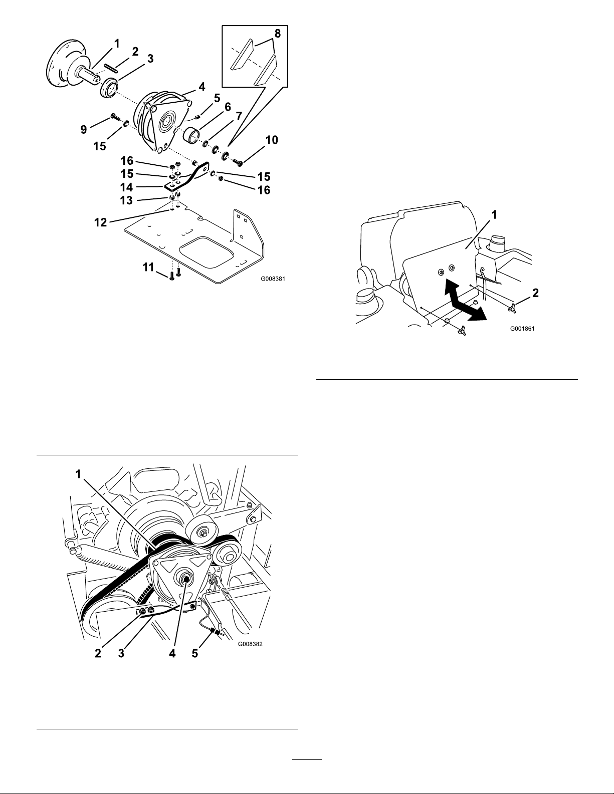
Figure4
1.Stubshaft9.Bolt(5/16x1inch)
2.Key10.Existingclutchbolt,torque
3.Clutchadapter,installas
shown
4.Newclutch12.Existingholesinmachine
5.Electricalconnection
6.Retainer
7.Flatwasher(.469x.922
inch)
8.Topviewofcurved
washers,installasshown
to50ft-lb
11.Carriagebolt(5/16x1
inch)
13.Spacers
14.Clutchstop,ensuretheit
istwistedasshown
15.Flatwasher(.344x.688
inch)
16.Locknut(5/16inch)
5.InstallthePTOdrivebeltontotheclutch(Figure2).
Ensurethebeltisroutedcorrectly.
6.Installthespringfortheidlerarm.
7.Usingtheexistingholesfortheoldclutchstop,install
thenewclutchstoptothemachinewith2carriage
bolts(5/16x1inch),2spacers,2atwashers(.344
x.688),2locknuts(5/16inch)(Figure4).Ensure
thetwistintheclutchstopisasshowinFigure4
andFigure5.
8.Plugtheelectricalconnectionstogether(Figure5).
9.Installthefrontenginepanel(Figure6).
Figure6
1.Frontenginepanel2.Knob
Figure5
1.PTOdrivebelt4.Clutchbolt
2.Nutsandbolts5.Electricalconnection
3.Clutchstop,ensureitis
twistedasshown
3
Page 4

Maintenance
AdjustingtheElectricClutch
ServiceInterval:Every500hours
Theclutchisadjustabletoensureproperengagement
andproperbraking.
1.DisengagethePTO,movethemotioncontrollevers
totheneutrallockedpositionandsettheparking
brake.
2.Stoptheengine,removethekey,andwaitforall
movingpartstostopbeforeleavingtheoperating
position.
3.Unlatchtheseatandtipitforward.
4.Loosenthefrontenginepanelknobsandremove
thepanel.
5.PulluponthespringloadedidlerpulleyforthePTO
drivebeltandremovethebeltfromtheclutchpulley
(Figure7).
Figure8
1.Clutch4.Clutchcenterbolt
2.Twoboltsandnutsfor
clutchstrap
3.Rubberclutchstrap
5.Electricalconnection
9.Inserta0.015–0.021inch(0.381–0.533mm)feeler
gaugethroughoneinspectionslotinthesideofthe
assembly.Makesureitisbetweenthearmatureand
therotorfrictionsurfaces(Figure9).
10.Tightenthelocknutsuntilthereisslightbindingon
thefeelergaugebutitcanbemovedeasilywithinthe
airgap(Figure9).
11.Repeatthisfortheremainingslots.
12.Checkeachslotagainandmakeslightadjustments
untilthefeelergaugebetweentherotorandarmature
hasveryslightcontactbetweenthem.
Figure7
1.Springloadedidlerpulley3.PTOdrivebelt
2.Clutch4.Gearbox
6.Unplugtheelectricconnectionfortheclutch
(Figure8).
7.Removethetwoboltsholdingtherubberclutch
straptothemowerframe(Figure8).
8.Removethecenterboltholdingtheclutchto
theengineshaftandremovetheclutchandkey
(Figure8).
Figure9
1.Slot
2.Adjustingnut
3.Feelergauge
13.Installtheclutchtotheengineshaftwiththekey.
14.ApplyblueLoctite®(orequivalent)tothecenter
bolt.
15.Whileholdingthecrankshaftatthebackofthe
machine,installthecenterboltandtorqueitto50
ft-lbs(68N-m)(Figure8).
16.Installtherubberclutchstraptothemowerframe
withthetwopreviouslyremovedboltsandnuts
(Figure8).
4
Page 5

17.PulluponthespringloadedidlerforthePTOdrive
beltandinstallitontotheclutchpulley(Figure7).
18.Plugintheelectricconnectionfortheclutch
(Figure8).
19.Installthefrontenginepanelandtightentheknobs.
20.Lowerdowntheseat.
5
Page 6

Notes:
6
Page 7

Notes:
7
Page 8

 Loading...