

Page 1
LightKit
GrandStand
ModelNo.114-3505
®
Installation
LooseParts
Usethechartbelowtoverifythatallpartshavebeenshipped.
FormNo.3373-815RevA
Mower
InstallationInstructions
ProcedureDescription
1
2
1
InstallingtheBrackets
Partsneededforthisprocedure:
2Bracket
4
Bolt(3/8x1inch)(selftapping)
Bracket2
Bolt(3/8x1inch)(selftapping)
Rightlight1
Leftlight(hasbuttonswitch)
Locknut(5/16inch)
Wireharness1
Fuse(15amp)
Convolutedtube
Plastictie8
Frictionwasher2
Y-Adapter1
Qty.
Use
4
1
2
1
2
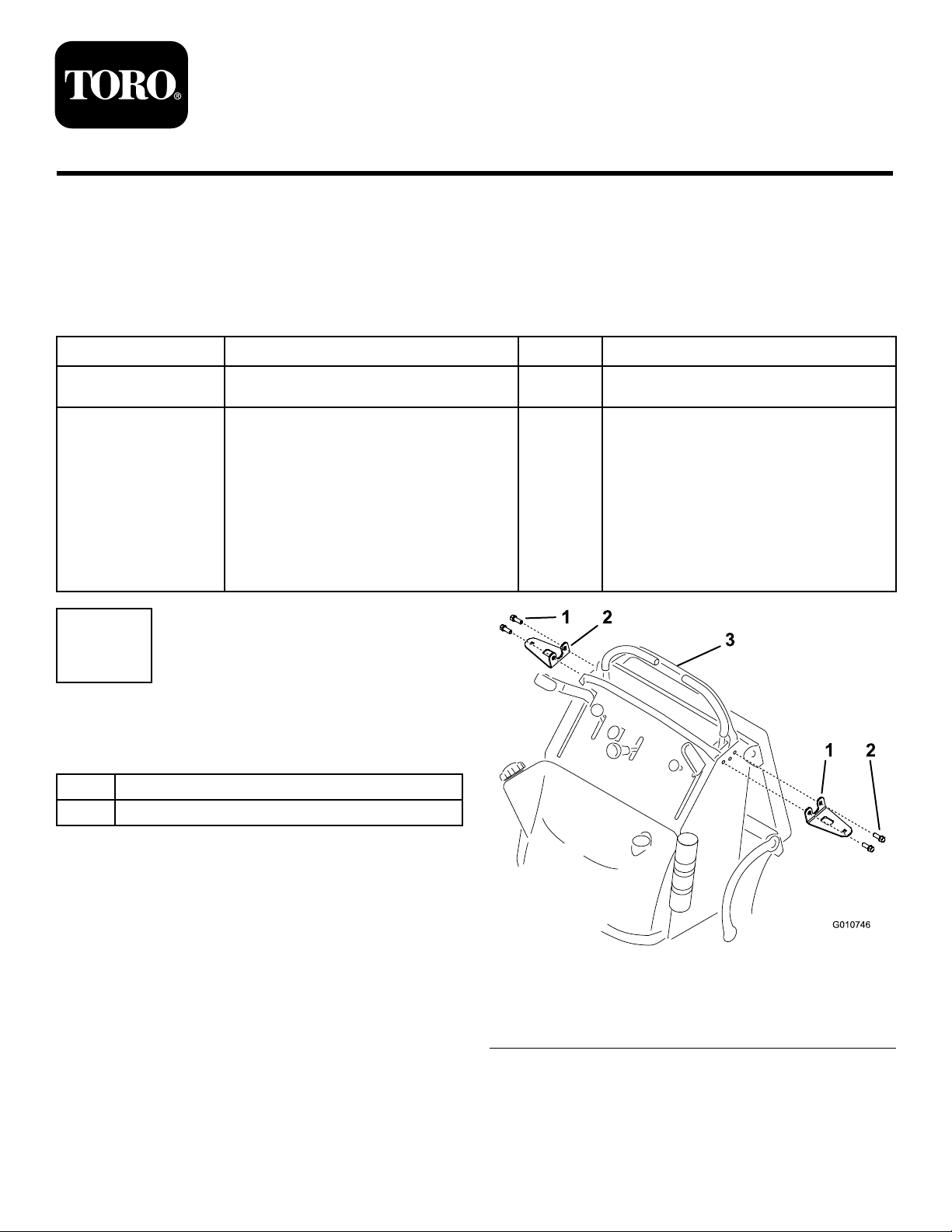
Installthebrackets.
Installthelights.
Procedure
1.Stoptheengine,settheparkingbrake,andremovethe
keyfromtheignitionswitch(Figure1).
2.Removethenegative(-)batterycablefromthebattery.
3.Installthe2bracketstothesideofthemachinewith4
bolts(3/8x1inch).
Note:Thesearethread-forming(self-tapping)bolts
andtheframeholesdonotrequiretapping.
©2012—TheT oro®Company
8111LyndaleAvenueSouth
Bloomington,MN55420
Registeratwww.T oro.com.
1.Self-tappingbolt(3/8x1
inch)
2.Bracket
OriginalInstructions(EN)
PrintedintheUSA.
AllRightsReserved
Figure1
3.Controllevers
*3373-815*A
Page 2

2
InstallingtheLights
Partsneededforthisprocedure:
1Rightlight
1
Leftlight(hasbuttonswitch)
2
Locknut(5/16inch)
1Wireharness
1
Fuse(15amp)
2
Convolutedtube
8Plastictie
2Frictionwasher
1Y-Adapter
Procedure
1.Installtheconvolutedtubeontotheexposedwires
connectedtothelights.
lightandtestthefrictiontomovelight.Loosenor
tightenthenuttocontrolthefrictionholdingthe
lightandallowingthelighttobeaimed.
3.Discardthe2nutsincludedwiththelights.
4.Installtheleft-handlight(withthebuttonswitch)to
theleftbracketwithalocknut(5/16inch),afriction
washer,andalockwasherandboltincludewiththe
light(
Figure3).
Note:Ensurethelightisinplacesothefrictionallows
thelighttopivotandswivel.
5.Installtherightlighttotherightbracketwithalocknut
(5/16inch),africtionwasher,andalockwasherand
boltincludedwiththelight(Figure3).
Note:Ensurethelightisinplacesothefrictionallows
thelighttopivotandswivel.
Note:Use4plastictiesoneachendoftheconvoluted
tubetosecureittothewires(Figure3).
2.Slidethelightconnectorsintotheholesinthebrackets
(Figure2).
Figure2
1.Rightlight
2.Bracketinstalled
3.Leftlight(hasbutton
switch)
Note:Thelockwashertsinsidethefrictionwasher
andcentersthefrictionwasher.
Important:Donotovertightenthehardwarefor
thelights.Gentlytightenthenuttosecurethe
1.Leftlight(hasbutton
switch)
2.Locknut(5/16inch)
3.Lockwasherincludedwith
light
4.Frictionwasher
5.Bracketinstalled
Figure3
6.Boltincludedwithlight
7.Rightlight
8.Plastictie
9.Convolutedtube
2
Page 3

6.Removethehairpincottersecuringtherearcushion
g018322
1
2 3
1
bracket(Figure4).
7.Slidethebushingnexttothemachine(Figure4).
8.Lowertherearcushionbracketontotheplatform
(Figure4).
Figure5
1.2-wireconnector3.3-wireconnector
2.Wireharness
11.Routethewireharnessdowntothefuseblock.
12.Locatetheshortconnectorbehindthefuseblockand
removetheinsulatorcapfromtheconnector.
Figure4
1.Hairpincotter3.Rearcushionbracket
2.Bushing
9.Routethelightkitwireharnessinfrontofthecontrol
cablesandnearthetractionunitwireharness.
10.Plugthewireharnessintothelights(
Note:Therightlighthasa2-wireconnectorand
theleftlight(withthebuttonswitch)hasa3-wire
connector.
Figure5).
3
Page 4

13.InstalltheY-adapter.
g018573
6
4
3
6
2
1
5
g018576
1
•PlugthesingleendoftheY-adapterintotheshort
connectorbehindthefuseblock(Figure6).
•Plugthewireharnessforthelightsintotheother
endoftheY-adapter(Figure6).
•PlugthewireharnessfortheHydraulicCooling
Assembly(ifpresent)intotheY-adapter(
Figure6).
Figure7
1.Fuse
15.SecuretheY -adaptertothemainwireharnesswitha
wiretiesuppliedinthekit.
Note:PositiontheY-adaptersothatthefusesarein
anuprightposition(
Figure6).
Figure6
1.Wireharnessforeither
theLightsortheHydraulic
SystemCoolingAssembly
2.Wireharnessforeither
theLightsortheHydraulic
SystemCoolingAssembly
3.Y-adapter6.Mainwireharness
4.Shortconnectorbehind
5.Fusebox
14.Installthefuse(Figure7).
thefuseblock
16.Securethelightkitwireharnesstothetractionunit
with3plastictiessuppliedinthekit.
17.Installtherearcushion(
Figure4).
18.Installthenegative(-)batterycabletothebattery.
Operation
OperatingtheLights
Note:Thelightscanonlybeonwhentheignitionswitch
isintheRunposition.
1.WiththeignitionswitchintheRunposition,turnthe
lightsonoroffbydepressingthebuttonswitchonthe
leftlight.
2.Pivotorswivelthelightstothedesiredposition.
4
 Loading...