

Page 1
Heat Shield Kit
For Dingo TX Traction Unit
Model No. 114–1289
Installation
Loose Parts
Use the chart below to verify that all parts have been shipped.
Form No. 3358-251 Rev A
Installation Instructions
Step
1
2
3
Step
1
Preparing the Machine
Description
No parts required
No parts required
Heat shield with large hole
Heat shield
Mufer clamp
U-bolt
Flat washer (5/16 inch)
Flange nut (1/4 inch)
Bolt (1/4 x 3/4 inches)
Bolt (#10 x 1/2 inch)
Flat washer (7/32 inch)
Qty.
–
–
1
1
1
1
7
7
5
1
1
Contact with hot surf aces may cause
per sonal injur y .
K eep hands, feet, f ace, clothing and other
body par ts a w ay fr om hot surf aces.
Prepare the machine.
Remove the existing heat shield.
Install the existing heat shield.
Use
No Parts Required
Procedure
1. P ark the mac hine on a flat surface , lo w er the
loader ar ms to the g round, set the parking
brak e , stop the engine , and remo v e the k ey
from the ignition.
2. Disconnect batter y neg ati v e cable .
3. Allo w all the mac hine components to
thoroughly cool before installing the kit.
© 2007—The Toro® Company
8111 Lyndale Avenue South
Bloomington, MN 55420
Register at www.Toro.com. Original Instructions (EN)
Allo w all the machine components to
thor oughl y cool bef or e installing the kit.
Printed in the USA.
All Rights Reserved
Page 2
Step
2
Removing the Existing Heat
Shield
No Parts Required
Procedure
1. Raise the hood.
2. R emo v e the 4 bolts holding the oil cooler to
the frame of the mac hine ( Figure 1 ).
3. R emo v e the 2 bolts and loc kw ashers from
the heat shield attac hed to the pump mount
( Figure 1 ). R etain these for installing the new
heat shield.
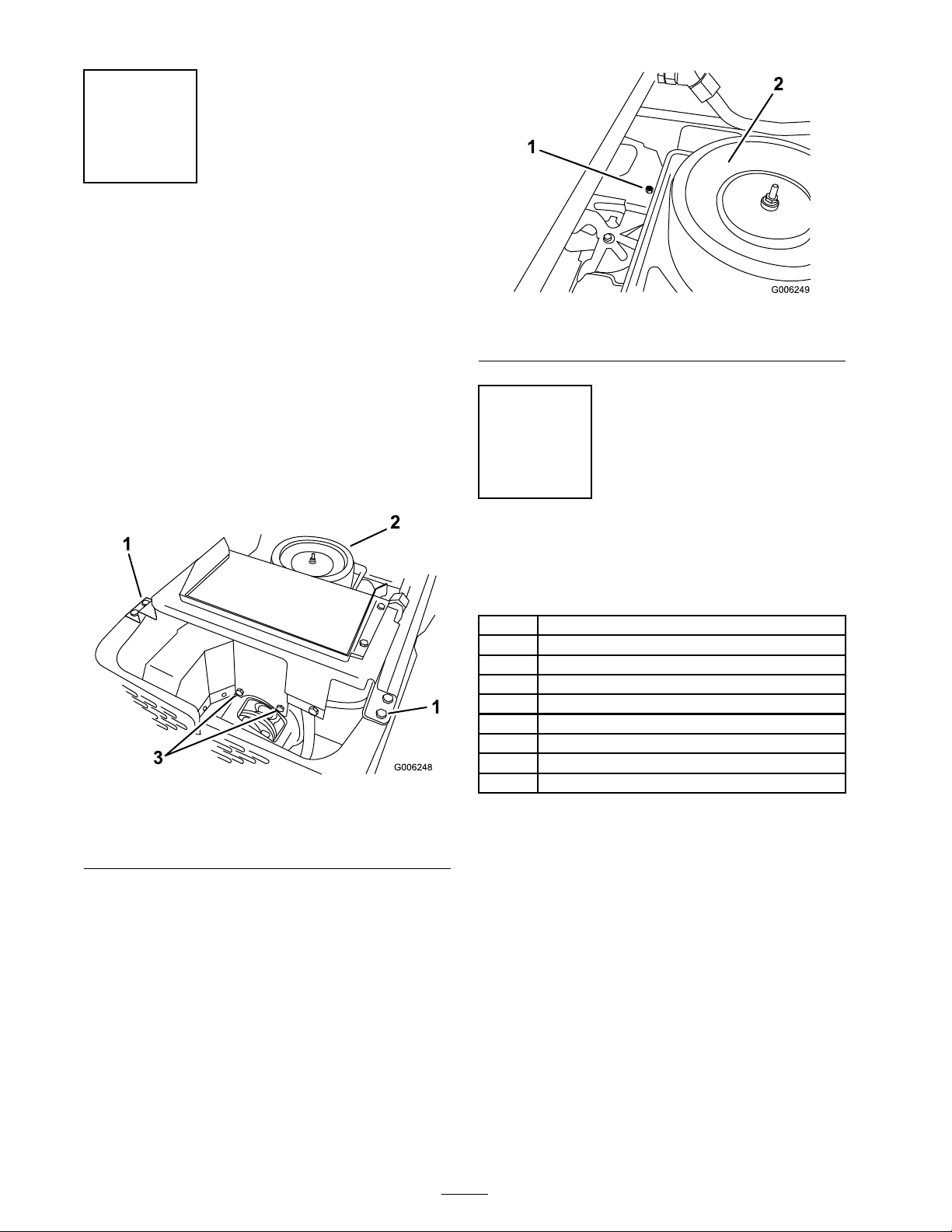
Figure 2
1. Top bolt in heat shield 2. Air cleaner
Step
3
Installing the New Heat
Figure 1
1. Bolts holding oil cooler 3. Bolts and lock washers
attached to pump mount
2. Air cleaner
4. R emo v e the air cleaner co v er from the engine
to g ain access to the top bolt in the heat shield.
5. R emo v e the one bolt from the top of the heat
shield ( Figure 2 ).
6. R emo v e the heat shield assembly from the
mac hine . Raise the oil cooler to allo w more
space to remo v e the heat shield.
Shield
Parts needed for this step:
1
Heat shield with large hole
1
Heat shield
1
Mufer clamp
1
U-bolt
7
Flat washer (5/16 inch)
7
Flange nut (1/4 inch)
5
Bolt (1/4 x 3/4 inches)
1
Bolt (#10 x 1/2 inch)
1
Flat washer (7/32 inch)
Procedure
1. Bolt the tw o for med heat shield par ts tog ether
with 5 bolts (1/4 x 3/4 inc hes), 5 flat w ashers
(5/16 inc h), and 5 flang e n uts (1/4 inc h) as
sho wn in Figure 3 .
2
Page 3

Figure 3
1. Bolt (1/4 x 3/4 inches) 4. Flange nut (1/4 inch)
2. Flat washer (5/16 inch)
3. Heat shield with large hole
5. Heat shield
2. Lift the oil cooler up and position the heat
shield in front of the engine manifold.
3. Install the heat shield to the pump mount with
the previously remo v ed bolts and loc k w ashers .
4. Install the heat shield to the top of the engine
with a bolt (#10 x 1/2 inc h) and a flat w asher
(7/32 inc h) ( Figure 4 ).
5. Install the co v er onto the engine air cleaner .
6. Deter mine the cor rect position to install the
m uffler clamp . R efer to Figure 4 for the cor rect
position and serial n umbers .
7. Install the m uffler clamp to the exhaust
manifold with a U-bolt, 2 flat w ashers (5/16
inc h), and 2 flang e n uts (1/4 inc h) ( Figure 4 ).
Figure 4
1. Flange nut (1/4 inch)
2. Flat washer (5/16 inch)
3. Holes for machines with
serial numbers 270000001
and up
4. Mufer clamp
5. U-bolt 11. Holes for machines with
6. Exhaust manifold
7. Install bolts and lcok
washers into the pump
mount
8. Heat shield assembly
9. Flat washer (7/32 inch)
10. Bolt (#10 x 1/2 inch)
serial numbers 269999999
and below
8. Install the oil cooler to the frame of the
mac hine with the previously remo v ed bolts .
9. Close the hood.
3
Page 4

 Loading...