

Page 1
Brake Lever Kit
For 2006 and Before TX Compact Utility Loaders
Model No. 114–1261
Loose Parts
Use the chart below to verify that all parts have been shipped.
Form No. 3357-908 Rev A
Installation Instructions
Step
1
2
No parts required
Right control panel plate
Brake lever
Bushing
Leaf spring
Shoulder bolt
Locknut
Cotter pin
Knob
Step
1
Removing the Brake Lever
No Parts Required
Description
Qty.
–
1
1
1
1
1
1
1
1
Remove the brake lever.
Install the new brake lever.
Use
Procedure
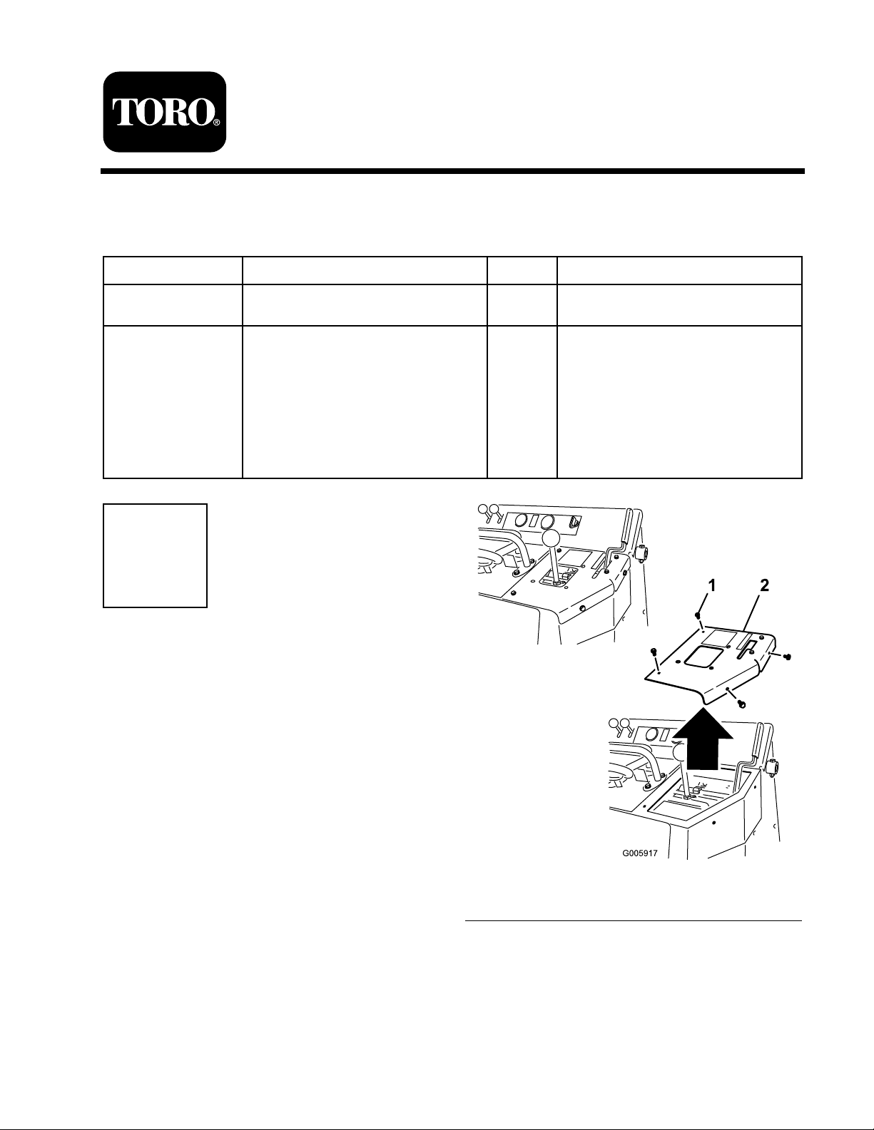
1. R emo v e and sa v e the 4 bolts securing the right
control panel plate and remo v e and discard the
plate ( Figure 1 ).
© 2007—The Toro® Company
8111 Lyndale Avenue South
Bloomington, MN 55420
Figure 1
1. Bolt 2. Right control panel plate
2. If y ou are installing this kit on a European,
CE cer tified compact utility loader , remo v e
the loader ar m lev er loc k, spring, w asher , and
hair pin cotter from the plate before discarding
it ( Figure 2 ). Y ou will need to install these par ts
on the new plate .
Register at www.Toro.com. Original Instructions (EN)
Printed in the USA.
All Rights Reserved
Page 2
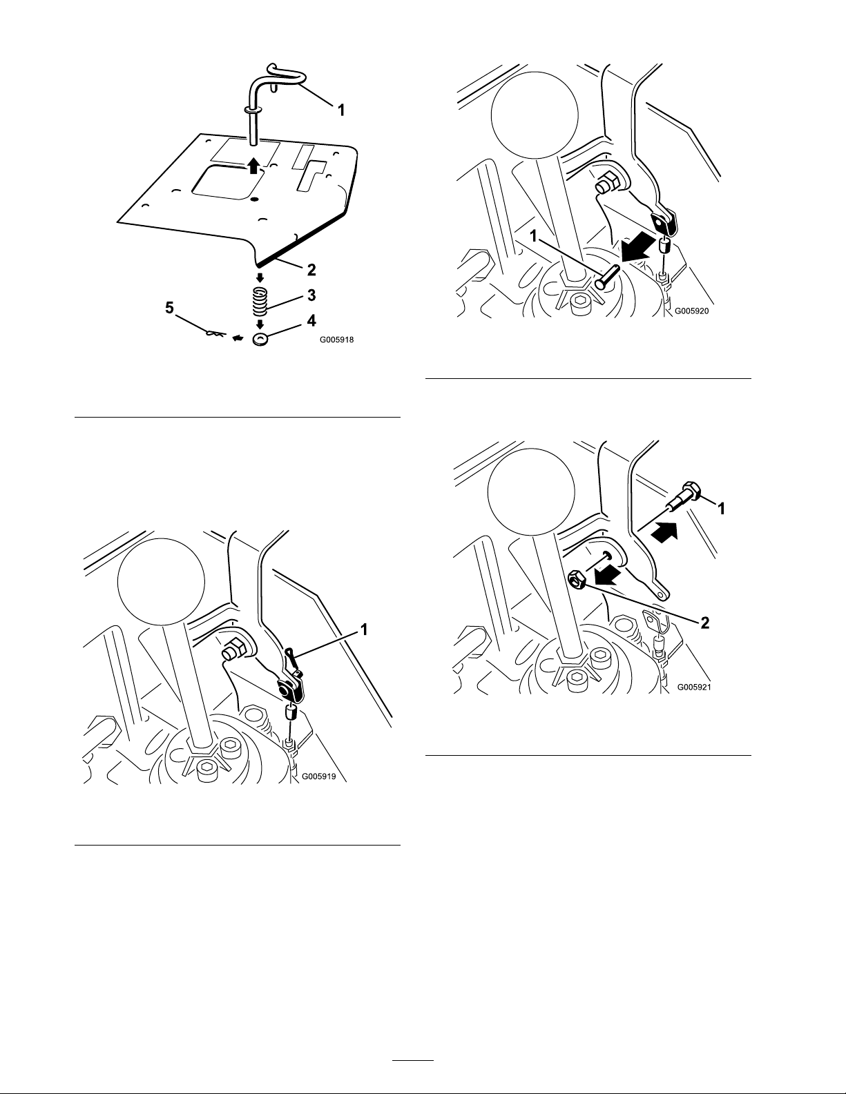
Figure 2
1. Loader arm lever lock 3. Washer
2. Spring 4. Hairpin cotter
3. R emo v e the cotter pin ( Figure 3 ) and clevis
pin ( Figure 4 ) whic h secure the brak e cable
clevis to the brak e lev er . Discard the cotter pin
and sa v e the clevis pin for use in installing the
brak e cable clevis to the new brak e lev er .
Figure 4
1. Clevis pin
4. R emo v e and discard the shoulder bolt and n ut
securing the brak e lev er ( Figure 5 ).
Figure 5
1. Shoulder bolt
2. Nut
1. Cotter pin
5. R emo v e and discard the brak e lev er ( Figure 6 ).
Figure 3
2
Page 3
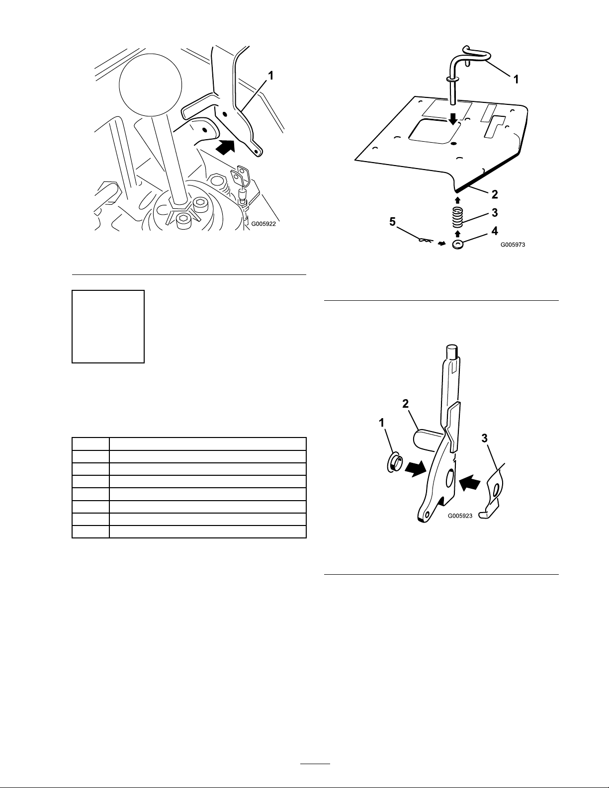
Figure 6
1. Brake lever
Step
2
Installing the New Brake
Lever
Parts needed for this step:
1
Right control panel plate
1
Brake lever
1
Bushing
1
Leaf spring
1
Shoulder bolt
1
Locknut
1
Cotter pin
1
Knob
Procedure
Figure 7
1. Loader arm lever lock 3. Washer
2. Spring 4. Hairpin cotter
2. Install the bushing and leaf spring onto the
new brak e lev er as illustrated in Figure 8 .
Figure 8
1. Bushing 3. Leaf spring
2. Brake lever
1. If y ou are installing this kit on a European,
CE cer tified compact utility loader , install the
loader ar m lev er loc k, spring, w asher , and
hair pin cotter onto the new plate ( Figure 7 ).
3. Install the brak e lev er assembly to the traction
unit using the new shoulder bolt and loc kn ut
( Figure 9 ).
3
Page 4

Figure 9
1. Shoulder bolt 2. Locknut
Figure 11
1. Cotter pin
4. P osition the brak e cable clevis onto the brak e
lev er and secure it with the clevis pin y ou
remo v ed previously ( Figure 10 ).
Figure 10
1. Clevis pin
5. Secure the clevis pin with a new cotter pin,
bending the ends to hold it in place ( Figure 11 ).
6. Install the new right control panel plate o v er
the brak e lev er and secure it with the 4 bolts
y ou remo v ed previously ( Figure 12 ),
Figure 12
1. Bolts removed previously 3. Right control panel plate
2. Knob
7. Install the brak e lev er knob ( Figure 12 ).
8. Place the brak e in the On position.
4
Page 5

9. Star t the engine .
10. Mo v e the traction unit using the traction
control handle .
T he engine should stop . If it does not, and
the traction unit mo v es , ensure that the brak e
cable is connected to the brak e lev er and install
it using the clevis pin and cotter pin. If the
cable w as connected, ha v e y our brak es c hec k ed
b y an A uthorized Ser vice Dealer .
11. Star t the engine .
12. Place the brak e in the Off position.
13. Mo v e the traction unit using the traction
control handle .
If the engine stops when y ou tr y to mo v e ,
complete the follo wing:
A. Loosen the bolts securing the brak e loc king
plate ( Figure 13 ).
Figure 13
1. Bolts
2. Brake locking plate (under
the right control panel
plate)
B . Slide the brak e loc king plate forw ard and
tighten the screws .
C . R e peat ste ps 11 through 13 to test the
adjustment.
5
Page 6

Page 7

Page 8

 Loading...