

Page 1
Parts needed for this step:
2
Wheel pivot bushing (109-6041)
4
Nylon washer (77-0350)
2
Locknut (5/16-inch) (104-8300)
2
Flat washer (98-3499)
Procedure
Form No. 3358-329 Rev B
Front Height Adjuster Kit
For 66cm Heavy-Duty Rear Bagger Lawn Mowers
Model No. 112-9715
Installation Instructions
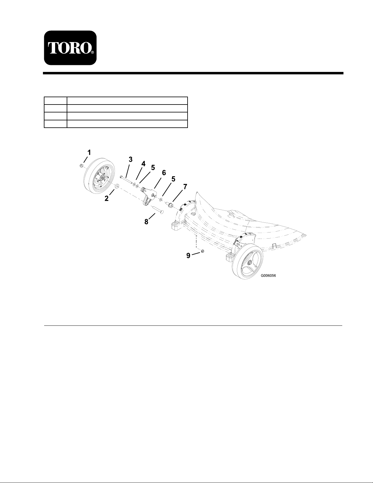
Figure 1
1. Locknut (3/8 inch; not in kit) 6. Pivot arm assembly (not in kit)
2. Wheel spacer (not in kit)
3. Hex head screw (5/16 x 3-1/4 inch; not in kit) 8. Wheel screw (3/8 x 2-1/2 inch; not in kit)
4. Flat washer
5. Nylon washer
1. R emo v e the front wheels and sa v e all the
hardw are .
2. R emo v e the pi v ot ar m assemblies from the
mo w er housing and discard the loc kn uts
7. Wheel pivot bushing
9. Locknut (5/16 inch)
Note: W hen installing eac h nylon w asher
betw een the outer w asher and the wheel pi v ot
bushing, ensure that y ou do not pinc h the
nylon w asher ( Figure 2 ).
(5/16-inc h) ( Figure 1 ).
3. Disassemble the pi v ot ar m assemblies , and
discard the flat w ashers and the wheel pi v ot
bushings .
4. Assemble the pi v ot ar m assemblies (including
the par ts pro vided in the kit) as sho wn in
Figure 1 .
5. Install the updated pi v ot ar m assemblies to the
mo w er housing ( Figure 1 ).
© 2007—The Toro® Company
8111 Lyndale Avenue South
Bloomington, MN 55420
Register at www.Toro.com. Original Instructions (EN)
Printed in the USA
All Rights Reserved
Page 2
Figure 2
1. Flat (outer) washer
2. Nylon washer 5. Wheel pivot bushing
3. Hex head screw
4. Pivot arm assembly
Note: T or que the hex head screws and
loc kn uts (5/16 inc h) to 200 to 250 in-lb (22.6
to 28.2 N·m).
Note: If y ou cannot easily rotate a pi v ot ar m
assembly , loosen the bolt a quar ter tur n until
y ou ac hiev e the desired tension.
6. Install the front wheels using the loc kn uts (3/8
inc h) that y ou previously remo v ed ( Figure 1 ).
Note: T or que the loc kn ut (3/8 inc h) on eac h
wheel to 250 to 400 in-lb (28.2 to 45.2 N·m).
2
 Loading...