

Page 1

Deck Belt Service Kit
For LX460 Tractors
Model No. 112-5881
Installation
Loose Parts
Use the chart below to verify that all parts have been shipped.
Form No. 3356-158 Rev B
Installation Instructions
Step
3
5
Important: R ead and under stand these instr uctions bef or e perf or ming the pr ocedur es
described. If y ou ar e not a trained and experienced ser vice and r epair technician, contact an
Authoriz ed Ser vice Dealer .
Note: Sa v e these instr uctions and refer to them when ordering re placement par ts .
Note: Deter mine the left and right sides of the mac hine from the operating position.
Belt
Lower PTO lever
Flange locknut
Description
Step
1
Preparing for Service
Qty.
1
1
2
Replace the upper deck belt.
Install the new lower PTO lever.
Step
2
Removing the Deck
Use
No Parts Required
Procedure
1. Mo v e the tractor to lev el g round.
2. Shut off the engine , w ait for all mo ving par ts
to stop , and remo v e the ignition k ey .
3. Set the parking brak e .
4. Lo w er the mo w er dec k to the lo w est position.
5. Ensure that the PTO lev er is in the diseng ag ed
(Off) position.
6. Allo w the m uffler and engine to cool.
© 2006—The Toro® Company
8111 Lyndale Avenue South
Bloomington, MN 55420
Register at www.Toro.com. Original Instructions (EN)
No Parts Required
Procedure
Important: R etain all hard w ar e or par ts
r emo v ed unless stated otherwise.
1. Use a 1/2-inc h soc k et and ratc het to loosen
the n ut that secures the left side of the engine
pulley belt guide to allo w the belt to clear the
guide ( Figure 1 ).
Printed in the USA.
All Rights Reserved
Page 2
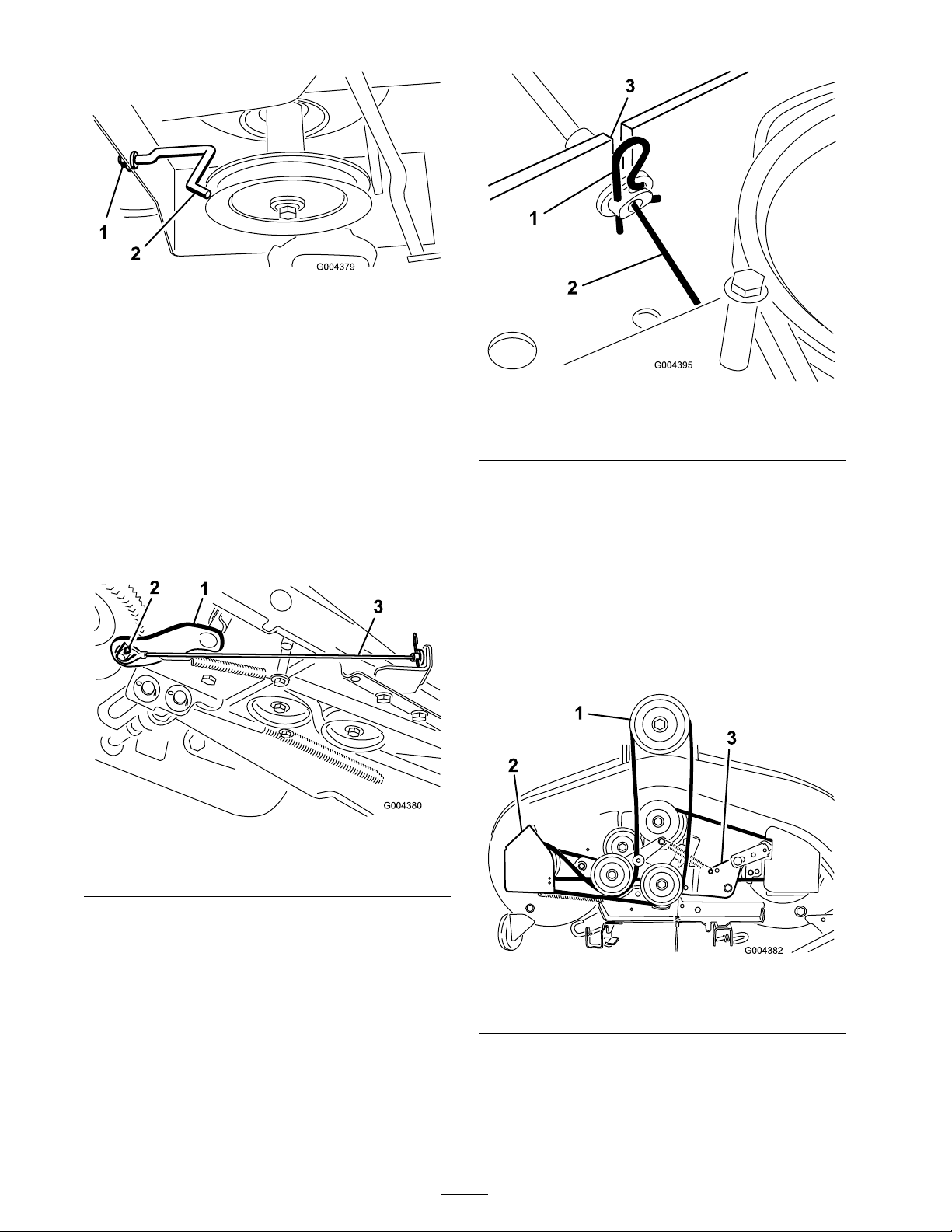
Figure 1
1. Belt guide nut 2. Engine pulley belt guide
2. Use a 1/4-inc h soc k et and ratc het to remo v e
the engine pulley belt guide .
Note: Note in whic h hole the belt guide
mounts for re-installation later .
3. R emo v e the belt from the engine pulley .
4. R emo v e and discard the cotter pin and flat
w asher that secure the loop end of the dec k
eng ag ement cable to the lo w er PTO lev er
( Figure 2 ).
Figure 3
1. Hairpin clip 3. Cross brace slot
2. Deck engagement cable
7. At the cable end, remo v e the hair pin clip ,
pull bac k on the cable housing until the metal
por tion of the cable is in the cross brace slot,
and lift the cable out of the slot ( Figure 3 ).
Note: T he straight leg of the hair pin clip g oes
through a hole in the fitting end of the cable .
8. Unhook the dec k eng ag ement cable spring
from the right hand idler brac k et on the dec k
( Figure 4 ).
Figure 2
1. Lower PTO lever 3. Deck engagement cable
2. Loop end of the cable
5. Slip the cable end off the PTO lev er stud.
6. F rom the right side of the unit, locate the other
end of the dec k eng ag ement cable on the cross
brace at the bac k of the dec k ( Figure 3 ).
Figure 4
1. Engine pulley 3. Right hand idler bracket
2. Left hand belt cover
9. R emo v e the dec k from under the tractor .
Note: R efer to the Operator’ s Manual for
instr uctions on ho w to remo v e the dec k from
under the tractor .
2
Page 3
Step
Step
3
Replacing the Upper Deck
Belt
Parts needed for this step:
1
Belt
Procedure
Note: R efer to Figure 4 for this procedure .
1. Use a 3/8-inc h soc k et and ratc het to remo v e
the 3 screws that secure the left belt co v er
from the cutting dec k.
2. Use a 5/8-inc h soc k et and ratc het and a
5/8-inc h bo x/open end wrenc h to loosen
(not remo v e) both the upper belt (engine to
dec k belt) and the idler pulleys on their idler
brac k ets .
4
Removing the Lower PTO
Lever
No Parts Required
Procedure
1. Lift the engine hood.
2. Drain the fuel tank or remo v e the fuel cap
from the tank, place a piece of thin plastic film
o v er the mouth of the tank, and re place the
fuel cap securely .
3. R emo v e the fuel tank mounting hardw are
( Figure 5 ).
Note: T his will pro vide sufficient belt guide
clearance to remo v e the belt from the pulleys .
3. R emo v e and discard the damag ed upper dec k
belt.
4. Install the new belt around the upper pulley of
the left spindle and route around the 2 upper
belt idler pulleys .
Note: Ensure that the belt is routed betw een
the 2 belt k ee pers and the pulleys on both idler
brac k ets .
5. Tighten both idler pulleys mounting hardw are .
6. Install the left belt co v er .
7. Set the dec k aside .
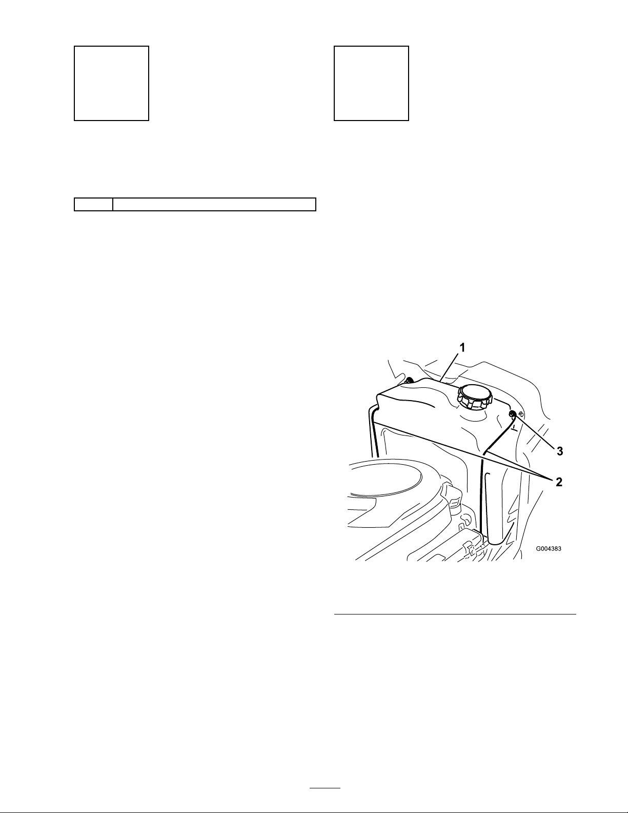
Figure 5
1. Fuel tank
2. Fuel tank brackets
4. Car efull y lift the tank up and out to pro vide
access to the bolt and n ut connection of the
stop eng ag ement brac k et and the upper and
lo w er PTO lev ers ( Figure 6 ).
3. Screws
3
Page 4
W atch that the fuel line connected to the
fuel tank is not kink ed, pulled fr om the
fuel tank nipple, and that ther e is not
str ess placed on the nipple that w ould
cause it to br eak.
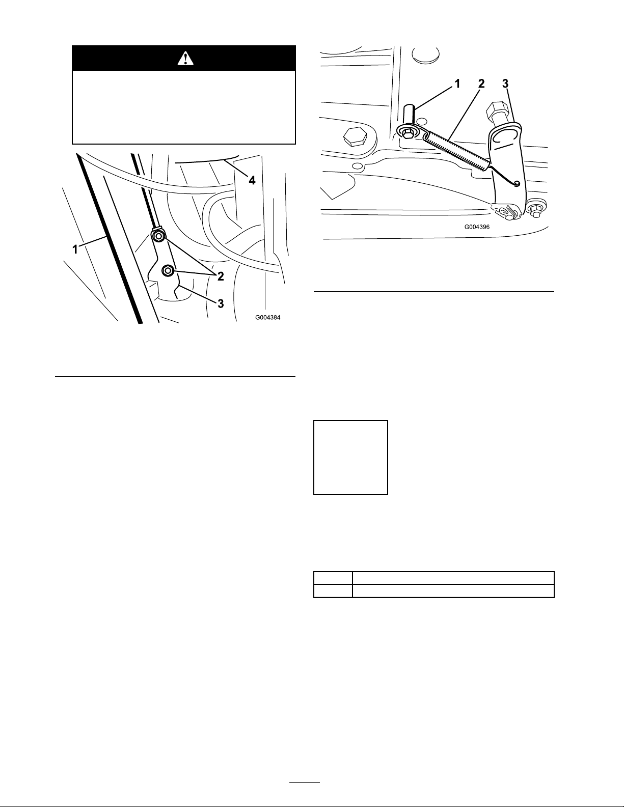
Figure 6
1. Steering column 3. Stop engagement bracket
2. Flange locknuts 4. Bottom of fuel tank
5. Use a 1/2-inc h soc k et and ratc het to remo v e
and discard the 2 flang e loc kn uts that secure
the connection of the stop eng ag ement brac k et
and the upper and lo w er PTO lev ers ( Figure 6 ).
Figure 7
1. Shoulder bolt 3. Lower PTO lever
2. Spring
7. Push up the lo w er PTO lev er to slip the split
plastic bushing out the hex hole in the frame .
8. Push the plastic split bushing off the round
section of the lo w er PTO lev er shaft.
9. R emo v e the lo w er PTO lev er do wn through
the hex hole of the frame . Discard the lo w er
PTO lev er .
Step
Note: T he 2 car riag e screws are secured in
the upper PTO lev er b y 2 speed n uts; do not
remo v e .
6. R emo v e the stop eng ag ement brac k et and
lo w er PTO lev er from the tw o screws attac hed
to the upper PTO lev er .
Note: If the spring attac hed to the lo w er
PTO becomes detac hed, install it as sho wn in
Figure 7 .
5
Install the New Lower PTO
Lever
Parts needed for this step:
1
Lower PTO lever
2
Flange locknut
Procedure
1. Install the new lo w er PTO lev er , using the 2
flang e loc kn uts pro vided in the kit.
R efer to Figure 8 and Figure 9 for the cor rect
assembly sequence .
4
Page 5
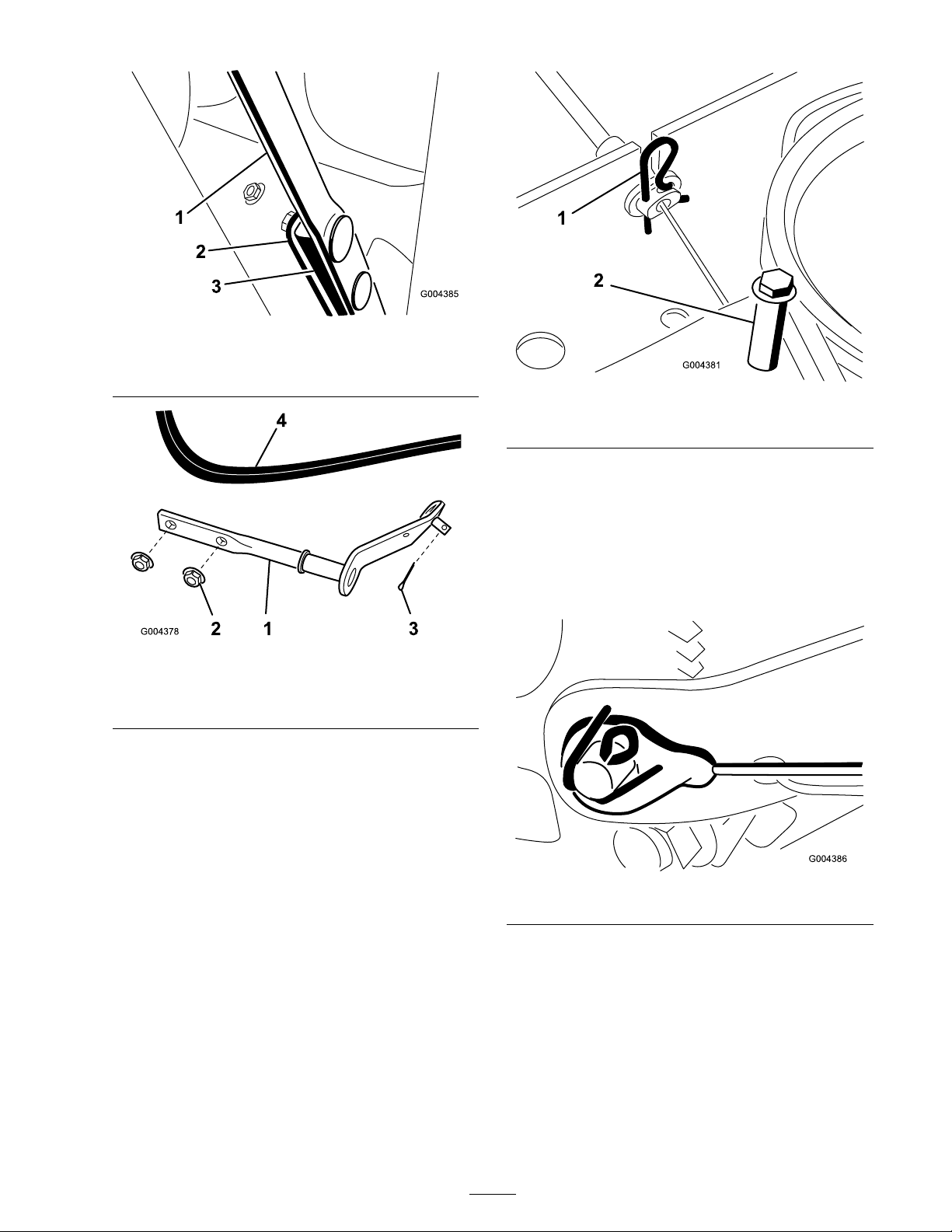
Figure 8
1. Upper PTO lever 3. Lower PTO lever
2. Stop engagement bracket
Figure 9
1. Lower PTO lever
2. Flange locknut (2)
3. Cotter pin (through the
stud)
4. Belt
Note: If the tank w as not remo v ed, remo v e
the plastic film from under the fuel cap and
re place the fuel cap .
Figure 10
1. Hairpin clip 2. Screw and spacer
7. Connect the dec k eng ag ement cable loop end
to the stud on the new lo w er PTO lev er with
the new cotter pin ( Figure 9 ).
Note: No flat w asher is required.
8. Inser t the cotter pin and bend the cotter pin
ends as sho wn in Figure 11 .
2. Install the fuel tank.
3. Slide the dec k under the tractor and connect
the lift links and the front hang er bar as
described in the Operator’ s Manual .
4. Attac h the dec k eng ag ement cable spring to
the right idler brac k et assembly .
5. Install the dec k eng ag ement cable spring to the
right idler brac k et assembly .
6. Install the dec k eng ag ement cable into the rear
cross brace ( Figure 10 ).
Figure 11
9. Place the upper dec k belt around the engine
pulley .
Note: Ensure that the belt is not twisted.
10. Install both engine pulley belt guides ( Figure 1 ).
11. With the dec k installed and lev eled properly ,
raise the dec k to its highest cutting position.
12. Ensure that the belt has sufficient clearance
with the stud on the lo w er PTO lev er when
5
Page 6

the PTO is in the eng ag ed position, the unit is
r unning, and the dec k is eng ag ed.
19. R emo v e the clevis pin and mo v e the lift cable
end loop to the hole indicated in Figure 12 .
Secure the lift cable with the clevis pin and
cotter pin previously remo v ed.
Do not get y our hands or feet near the
cutting deck when the engine is r unning .
13. Shut off the engine . If the clearance is g ood
with the dec k r unning in the highest position,
y ou ha v e completed the procedure .
Note: If the lo w er PTO lev er stud still
interferes with the upper dec k belt when
r unning in the highest cutting position, then
g o to the next ste p .
Note: T he follo wing ste p will result in the
cutting dec k cutting lo w er in all positions . T he
lo w est position ma y cause scalping if the dec k
wheels are not properly adjusted.
14. R elease the man ual PTO lev er in the
diseng ag ed position and lo w er the dec k to its
lo w est cutting height.
15. F rom the right or left side of the tractor , locate
the rear dec k lift ar m ( Figure 12 ).
20. R e peat ste ps 16 through 19 for the other lift
ar m.
21. Raise the dec k to its highest cutting position.
22. Ensure that the belt has sufficient clearance
with the stud on the lo w er PTO lev er when
the PTO is in the eng ag ed position. Chec k
this clearance when the unit is r unning and the
dec k eng ag ed.
Do not get y our hands or feet near the
cutting deck when the engine is r unning .
Figure 12
1. Deck lift bracket
2. Lift arm 5. Move the lift cable pin here.
3. Lift cable clevis pin
4. J-pin
16. Suppor t the dec k so that there is no w eight
hanging on the lift ar m.
17. Pull the J-pin out so that the lift ar m diseng ag es
from the dec k lift brac k et.
18. R emo v e the cotter pin and clevis pin that
secures the lift cable to the lift ar m ( Figure 12 ).
6
Page 7

Page 8

 Loading...