

Page 1
Form No. 3326-451
GTS 150 to GTS 200 Engine Conversion Kit
For 21-inch Super Recycler Lawn Mowers
Model No. 105-1293
Installation
Instructions
Loose Parts
Note: Use the following chart to identify the parts you need to install the kit.
Description Qty. Use
Engine screws 3 Installing the new engine
Throttle control and cable assembly 1 Replacing the new throttle control and cable
Cable ties 2 Installing the cable ties
Rope stop 1 Installing the rope stop
Engine decal (98-2002) 1 Installing the decal
Before Installing the Kit
Caution
2
If you leave the wire on the spark plug, someone
could accidently start the engine and seriously
injure you or other bystanders.
Disconnect the wire from the spark plug before
you install the kit. Set the wire aside so that it does
not accidentally contact the spark plug.
1. Disconnect the wire from the spark plug (Fig. 1).
1
Figure 1
1. Spark-plug wire 2. Fuel tank cap
2. If the engine is hot, allow it to cool down.
495
Warning
If you spill gasoline on a hot engine, it could ignite
and burn, causing serious personal injury.
Drain gasoline from a cold engine only.
2001 by The Toro Company
8111 Lyndale Avenue South
Bloomington, MN 55420-1196
All Rights Reserved
Printed in the USA
1
Page 2
3. Transfer the fuel from the fuel tank into a clean,
approved gasoline container.
4. Drain the engine oil. Refer to your Operator’s Manual
for more information.
Disassembling the Old
Components
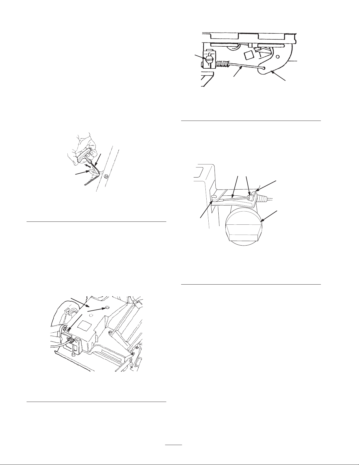
Removing the Starter Rope
Remove the starter rope from the rope guide (Fig. 2).
2
1
210
Figure 2
1. Rope guide 2. Starter rope
1
2
3
Figure 4
1. Cable clamp screw
2. Throttle cable
3. Throttle lever
Disconnecting the Blade Brake Cable
1. Disconnect the blade brake cable from the brake arm
(Fig. 5).
23
4
5
1
Removing the Cable Ties
Cut the cable ties that hold the cables to the handle.
Disconnecting the Throttle Cable
1. Remove the 2 bolts that secure the belt cover to the
deck (Fig. 3). Set the cover and the bolts aside.
1
2
Figure 3
1. Belt cover 2. Bolts
Figure 5
1. Brake arm
2. Brake cable
3. Brake cable fitting
4. Brake assembly
5. Dipstick
2. Use a pliers to squeeze the tabs on the top and bottom
of the cable fitting, and slide the brake cable out of the
brake assembly (Fig. 5).
2. Loosen the cable clamp screw and disconnect the
throttle cable from the throttle lever (Fig. 4).
2
Page 3

Removing the Blade Assembly
Remove the following items (see Figure 6):
• bolt
• lock washer
• accelerator
• blade
3
Installing the Conversion Kit
Installing the New Engine
1. Carefully set the new engine onto the housing (Fig. 8).
1
2
1
Figure 6
1. Bolt and lock washer
2. Accelerator
3. Blade
Removing the Old Engine
Remove the 3 engine screws and carefully lift the engine
off the housing (Fig. 7). Discard the screws and the engine.
1
2
Figure 8
1. New engine 2. New engine screw (3)
2. Secure the engine with 3 new engine screws (Fig. 8),
torquing them to 250 to 400 in-lb (28 to 45 N⋅m).
Installing the Blade Assembly
Install the blade assembly in the reverse order of its
removal. Refer to Removing the Blade Assembly on
page 3.
Important Torque the blade bolt to 50 ft-lb (68 N⋅m).
Replacing the Throttle Control and Cable
1. Pry up the tab on the backside of the control panel that
holds the old throttle control in place (Fig. 9).
2
Figure 7
1. Old engine 2. Engine screw (3)
12
1778
Figure 9
1. Back side of throttle
control
2. Tab
2. Remove the old throttle control assembly and discard it.
3. Install the new throttle control.
4. Secure the new throttle control by setting the tab in its
original position.
3
Page 4

5. Route the new throttle cable the same way as the old
cable had been.
6. Connect the new throttle cable to the throttle arm on the
engine (Fig. 10).
3
2. Loosen the jam nut on the brake cable (hand-push
models only) or the nut on the cable bracket (self-propel
models only). Insert a 3/16 to 1/4 in. (5 to 6 mm) thick
object between the brake lever and the handle.
3. Turn the cable adjuster on the brake cable (hand-push
models only) or pull down on the cable conduit
(self-propel models only) until you remove all the slack
from the wire.
1
2
4
m-3638
Figure 10
1. Cable clamp screw
2. Cable clamp
3. Throttle cable
4. Throttle arm
7. Move the throttle to the (Fast) position.
8. Push the throttle arm to the rear of the engine as far as
possible.
9. Install the new cable clamp and the cable clamp screw
to the engine (Fig. 10). Tighten the cable clamp screw
to lock the throttle cable in place.
10.Install the belt cover (Fig. 3).
Connect the Blade Brake Cable
Connect the blade brake cable in the reverse order of its
disconnection. Refer to Disconnecting the Blade Brake
Cable on page 2.
4. Tighten the nut.
Installing the Starter Rope
Install the starter rope in the rope guide (Fig. 12).
Installing the Rope Stop
Crimp the rope stop onto the starter rope about 2 inches
(5 cm) from the recoil opening on the engine (Fig. 12).
2
3
Figure 12
1. Rope stop
2. 2 in. (5 cm)
1
3. Decal P/N 98-2002
Adjusting the Blade Brake Cable
1. Move the control bar toward the handle until you
remove the slack in the cable (Fig. 11).
Note: The gap between the brake lever and the handle must
be 3/16 to 1/4 in. (5 to 6 mm).
1
2
3
4
Figure 11
1. Handle
2. Brake lever
3. 3/16 to 1/4 in. (5 to 6 mm)
4. Cable bracket
Installing the Cable Ties
Attach the cables to the handle using the new cable ties.
Installing the Decal
Install the new decal on the engine (Fig. 12).
Using the New Engine
To operate and maintain your new engine, refer to your
engine owner’s manual.
4
 Loading...