

Page 1

1
Operation & Maintenance Manual
For Commercial Use Only
SWB 26/8
Battery Sweeper
Form No L9730 © 2011 Tornado Industries, LLC Issue A 06/2011
https://harrissupplyind.com - To Order Parts Call 608-268-8080
Page 2

2
https://harrissupplyind.com - To Order Parts Call 608-268-8080
Page 3

3
Table of content
1 Safety information ...................................................................................................................................... 4
1.1 Safety and Warning Symbols ........................................................................................................... 4
1.2 General information .......................................................................................................................... 4
1.3 Operating information ....................................................................................................................... 4
1.4 Maintenance information .................................................................................................................. 5
1.5 Particular risks .................................................................................................................................. 5
1.6 Environmental protection .................................................................................................................. 6
1.7 Labels on the machine ..................................................................................................................... 6
2 Starting Up .................................................................................................................................................. 7
2.1 Unpacking and assembling .............................................................................................................. 7
2.2 Instruction ......................................................................................................................................... 8
2.3 Initial battery charge ......................................................................................................................... 8
2.4 Prior to starting up ............................................................................................................................ 8
2.5 Operation .......................................................................................................................................... 8
2.6 Stopping the machine ....................................................................................................................... 8
2.7 After completing work ....................................................................................................................... 9
3 Operation .................................................................................................................................................... 9
3.1 Method of operation ......................................................................................................................... 9
3.2 Operating and indicator elements .................................................................................................. 10
4 Technical Data .......................................................................................................................................... 11
5 Maintenance and Service ........................................................................................................................ 12
5.1 Maintenance Plan ........................................................................................................................... 12
5.2 Battery system ................................................................................................................................ 13
5.3 Side brushes ................................................................................................................................... 14
5.4 Rotary brush ................................................................................................................................... 15
5.5 Debris container ............................................................................................................................. 16
5.6 Dust vacuum ................................................................................................................................... 16
EC Declaration of Conformity ................................................................................................................... 17
https://harrissupplyind.com - To Order Parts Call 608-268-8080
Page 4

4
1 Safety information
1.1 Safety and Warning Symbols
All paragraphs in this manual referring to your
personal safety, the safety of your machine and
the environment protection are attributed one of
the following warning symbols:
Symbol
Hazardous for
Description
Safety Provisions
persons and goods
Safety Provisions in dangerous situation
caused by misuse inaccurate adherence
of instructions or prescribed work
routine.
CAUTION
the machine
Important information on handling the
machine in order to maintain operability.
Ecological hazard
the environment
Due to use of substances representing
an inherent danger to health of
environment
1.2 General information
In addition to the information provided
Before starting up the machine for the first
time, read the operating manual supplied
with it thoroughly as well as any separate
manuals provided with additional or
attachment devices and observe all the
information during work.
The equipment may only be operated,
serviced and repaired by personnel trained in
the operation of its use.
Particular attention should be paid to the
information regarding safety. Technical
expertise is the key to preventing errors
when operating the machine and ensuring
trouble-free operation.
The operating manual must always be kept
at the operating location of the machine and,
as a result, should be kept in a safe place on
the equipment.
The warning labels attached to the machine
provided important information concerning
safe operation. Illegible or missing labels
must be replaced by new ones.
For reasons of safety, always use original
spare parts.
1.3 Operating information
Before starting the machine up for the first
time, the battery to be used must be fully
charged, properly, by implementing the initial
battery charge routine. Please pay attention
to the operating manual provided with the
charging unit as well as the manual from the
battery manufacturer.
Tornado assumes no liability for damage to
the battery caused by a fault when the
battery is charged for the first time.
Check the operational safety of the machine
each time before starting it up! Clear any
faults immediately!
Before starting work, the operator must be
fully familiar with all adjustment, operating
and control elements as well as their
https://harrissupplyind.com - To Order Parts Call 608-268-8080
Page 5

5
respective function! It is too late to do this
when the machine is actually in operation!
Always wear heavy duty, non-slip footwear
when working with the machine.
The machine may only be used on those
surfaces which have been approved by the
contractor or person appointed by him.
When using the machine, it is essential to
pay attention to third parties, especially
children.
Accelerate the machine immediately after
switching on the brush head drive, otherwise
imprints of the brush could be produced.
The machine is not suitable for clearing up
hazardous, inflammable or explosive fluids,
dust or substances.
It is forbidden to use the machine in
potentially explosive atmospheres.
The side brush must be raised in order to
transport the machine.
The machine has been conceived for use on
level surfaces with a maximum gradient of
2%.
1.4 Maintenance information
Operating personnel must complete the
necessary daily and weekly maintenance
work. All other maintenance work must be
completed at your local Tornado authorized
service center.
The maintenance work and maintenance
intervals prescribed in the operating manual
must be adhered to.
Suitable tools must be used for cleaning and
maintenance work.
The machine must be inspected by a
recognized technical expert in respect of
operational safety, within the terms of the
applicable accident prevention laws, at
reasonable intervals (we recommend at least
once a year) and following modification or
repairs.
Spare parts must comply with the minimum
technical requirements stipulated by the
manufacturer! This is ensured by the use of
original spare parts.
The machine must be switched off prior to
cleaning or servicing it or to replacing parts.
The drive bar must be out of operation!
Always disconnect the battery plug before
starting any work on the electrical
installation.
When working in the area of the raised hood,
it must be hinged open fully to prevent it
being knocked shut or further open and down
unintentionally.
It is not permitted to clean the machine with a
pressure washer or steam blaster.
It is not permitted to use aggressive and
corrosive cleaning agents.
Allow the machine to dry after being cleaned,
e.g. over the weekend.
Only start the machine up when all the safety
equipment has been installed and brought to
its protecting position.
1.5 Particular risks
Electronics
In the case of defects in the electrical
installation, switch the machine off
immediately and clear the fault.
Work on the electrical equipment may only
be carried out by electricians who have
received the necessary training
The machine's electrical equipment must be
inspected/checked at regular intervals.
Defects, such as loose connections and
cable damage, must be rectified immediately.
Batteries
It is possible that sparking will occur when
connecting the batteries.
Batteries may only be handled and changed
by properly skilled maintenance personnel.
The machine has been set up for operation
using maintenance-free batteries. If other
battery types are used, the machine must be
set up for use with them by an authorized
Tornado service center.
Never lay any metallic objects or tools on
batteries - risk of short circuit!
https://harrissupplyind.com - To Order Parts Call 608-268-8080
Page 6

6
1.6 Environmental protection
A certain factual expertise is required in
order to use substances which could
represent a risk to health and the
environment.
Observe the applicable laws and local
regulations when disposing of waste.
Used batteries with the recycling symbol
contain reusable commodities. In accordance
with symbol with the crossed out bin, these
batteries must not be disposed of in domestic
waste.
1.7 Labels on the machine
The following safety and warning labels are
attached to the machine where easily legible.
Missing or illegible labels must be replaced
immediately.
Company logo
Rating plate
Maximum permissible
gradient
Filter shaker
Wear compensator for
side brush
Read and observe the
operating manual
Wear compensator for
rotary brush
https://harrissupplyind.com - To Order Parts Call 608-268-8080
Page 7

7
2 Starting Up
2.1 Unpacking and assembling Fig 1
Open the box, two people are required
to remove the machine from the protective
wrap and place it on the floor.
1. To fix the side brush (Fig 1/1) align the drive
pins on the side brush drive plate and secure
with the wing bolt and washer supplied.
2. Loosen the two knurled screws (Fig. 1/2)
holding the handle a few revolutions until the
handle can be raised and positioned. Set the
handle to a height comfortable for the user
and then tighten the knurled screws.
3. Remove the locking bolt (Fig 1/3) holding
the hood and pivot the hood open.
4. Fix the disassembled cable lug (Fig. 2) to the
corresponding battery contact. It is possible
that sparking will occur when connecting the
batteries!
5. Close the hood and lock in place with the
bolt.
6. The unit is now ready to operate.
Fig 2
Fig 1/2
Fig 1/1
Fig 1/3
https://harrissupplyind.com - To Order Parts Call 608-268-8080
Page 8

8
2.2 Instruction
Instructions to operators are required before
putting the machine into service.
Only technicians from your local, authorized
Tornado dealer are allowed to provide initial
instruction on how to use the machine.
2.3 Initial battery charge
Before starting the machine up for the
first time, the batteries to be used must
be fully charged, properly, by
implementing the initial battery charge
routine.
2.4 Prior to starting up
Carry out the following checks before starting the
machine:
1. Check the charge status of the batteries.
2. Check the levels of wear on the rotary brush
and side brush.
3. Check the fill level of the debris
container.
2.5 Operation
Please read the Safety Information in
Chapter 1. Before switching the machine
on, ensure that the drive bar (Fig.
3/3) on the handle has not been actuated.
1. Switch the machine on using the (Fig. 3/1)
button: rotary brush drive, dust vacuum and
side brush drive are ready to operate.
2. Lower the side brush to its working position
using the lever (Fig. 3/4). When working
without the side brush: do not lower the side
brush and press the button (Fig. 3/2) for the
side brush once. The green control lamp
goes out.
3. Actuate the drive bar (Fig. 3/3) on the
handle: the machine starts to work.
Start work immediately after actuating
the drive bar, otherwise imprints could
be produced on the floor. Release the
drive bar when driving over thresholds.
Fig.3
2.6 Stopping the machine
When the drive bar is released, the rotary brush
drive, dust vacuum and side brush drive switch
off automatically.
https://harrissupplyind.com - To Order Parts Call 608-268-8080
Page 9

9
2.7 After completing work
1. Drive to an appropriate maintenance area.
2. Stop the machine. Raise the side brush to its
idle position and switch the machine off.
3. Actuate the filter shaker.
4. Empty the debris container.
5. Check the brush space for accumulations of
dirt.
6. Check the charge status of the batteries.
It is not permitted to clean the machine
with a pressure washer or steam
blaster.
3 Operation
3.1 Method of operation
The Tornado SWB 26/8 is a machine designed to
sweep and clean waste from hard floors and
carpets. The side brush (Fig. 4/1) sweeps the dirt
from corners to a position in front of the rotary
brush (Fig. 4/2). The rotary brush sweeps the
larger particle dirt overhead into the debris
container (Fig. 4/3). The finer dust picked up is
drawn up by the suction turbine, fed into the filter
system (Fig. 4/4) and filtered out.
Only dust-free air is fed back into the ambient air.
The machine is equipped with maintenance- free
batteries (Fig. 4/5), a specially adapted, fully
automatic battery charger (Fig. 4/6) and a total
discharge signal transducer to protect it against
total discharge.
Fig. 4
https://harrissupplyind.com - To Order Parts Call 608-268-8080
Page 10

10
3.2 Operating and indicator elements
3.2.1 Operating panel
1. Control lamp for rotary brush drive, side
brush drive and suction turbine
2. ON/OFF button for rotary brush drive, side
brush drive and suction turbine
3. Control lamp for side brush drive
4. ON/OFF button for side brush drive
5. Control lamp for battery charger operation
6. Charge control indicator
7. Drive bar
Fig. 5/7
Fig. 5
ON/OFF button for rotary brush, side
brush and suction turbine (Fig. 5/1)
The button activates the rotary brush drive, side
brush drive and suction turbine so they are ready
to operate.
The side brush drive can be switched off
separately. The suction turbine cannot be
switched off separately which prevents the dust
vacuum being activated by accident.
To prevent unauthorized use of the
machine, switch the machine off using
the button (Fig. 5/1).
Control lamp for rotary brush drive, side
brush drive and suction turbine (Fig. 5/2)
The green control lamp indicates that the rotary
brush drive and suction turbine are ready to
operate. If the rotary brush or suction turbine is
overloaded, a safety shutdown is triggered and
the control lamp flashes.
ON/OFF button for side brush drive (Fig. 5/3)
The button can be used to switch off the side
brush drive independently of the rotary brush
drive and to activate it for use again.
Control lamp for side brush drive (Fig. 5/4)
The green control lamp indicates that the side
brush drive is ready to operate. If the side brush
is overloaded, a safety shutdown is triggered and
the control lamp flashes.
Control lamp for battery charger operation
(Fig. 5/5)
This control lamp indicates that the batteries are
being charged
Charge control indicator (Fig. 5/6)
During the charging process, the machine's
electronics system controls the machine is not
switched on inadvertently and indicates the
charge status. The battery charge status is
indicated by 4 green and 1 red LED.
The battery voltage is depicted in 5 levels:
> 25.1 V = all green LEDs on
> 24.5 V = bottom 3 green LEDs on
> 23.9 V = bottom 2 green LEDs on
> 22.7 V = bottom green LED on
< 22.7 V = red battery LED flashes
Drive bar (Fig. 5/7)
The drive bar switches all the drives which are
ready to operate on or off.
The drive bar serves to prevent damage.
If the drive bar is released during operation, all
the drives are switched off.
https://harrissupplyind.com - To Order Parts Call 608-268-8080
Page 11

11
3.2.2 Operating elements on the machine
1 Knurled screw for the handle
2 Shaking device lever
3 Debris container lock
4 Side brush lever
5 Charger cable flap
Fig. 6
Knurled screws for handle (Fig. 6/1)
The two knurled screws enable the handle
to be adjusted to a comfortable
height for the user.
Shaking device lever (Fig. 6/2)
In order to clean the filter in the dust
vacuum, switch the shaking device lever
several times quickly to the left and
right.
Debris container locks (Fig. 6/3)
Pull the lock lever up in order to remove
the debris container.
Side brush lever (Fig. 6/4)
Use the lever to lower or raise the side
brush.
Charger cable flap (Fig. 6/5)
The battery charger cable is located behind the
flap to the right beside the operating
panel. Pull the lock downwards
to open the flap.
Technical Data
Machine length
cm/in
80/32
Machine height (handle folded)
cm/in
60/24
Machine width
cm/in
70/28
Working width
cm/in
66/26
Rotary brush width
cm/in
40/16
Rotary brush diameter
cm/in
19/7
Area Coverage, theoretical
m²/sqft/h
2400/26000
Debris Container Volume
Liter/Gal
40/9
Filter Surface
m²/sqft
1.1/12
Nominal Voltage
V
24
Power Consumption, rotary brush drive
W/A
210/8.75
Power Consumption, side brush drive
W/A
48/2
Power Consumption, suction turbine
W/A
60/2.5
Weight without batteries
kg/lbs.
42/93
Weight with batteries
kg/lbs
56/124
Noise emission value
The sound pressure level (LpA) (at the ear of the operator)
measured according to DIN IEC 60335-2-72 under normal
working conditions:
dB (A)
70
Measurement inaccuracy (KpA):
dB (A)
2
https://harrissupplyind.com - To Order Parts Call 608-268-8080
Page 12

12
5 Maintenance and Service
General information
It is essential to pay attention to the information
in Chapter "Safety Information" before
completing any service or maintenance work!
By adhering to the maintenance work
recommended by us, you can be sure that the
machine is always ready to be put into operation.
Maintenance and repair work necessary on a
daily and weekly basis can be carried out by an
operator trained to complete the work, all other
Tornado system maintenance may only be
completed by personnel who are correspondingly
qualified and trained.
Please contact your nearest Tornado service
center or Tornado authorized dealer.
Failure to observe this annuls any rights to
claims under the terms of guarantee in respect of
resulting damage or consequential damage.
Always specify the serial number in the case of
inquiries and spare parts orders, refer to section
1.7 - Rating plate.
5.1 Maintenance Plan
System maintenance, customer
The following maintenance work must be
completed by the customer at the intervals
stipulated.
Activity
Interval
Daily
Weekly
Check the battery charge; recharge if necessary
o
Empty the debris container
o
Clean the brush space
o
Check the filter in the dust vacuum; clean, if necessary
o
Check the rotary brush and side brush; clean, if necessary
o
Check the sweeping pattern; readjust, if necessary
o
Check the sealing strips on the rotary brush for signs of wear; clean, if
necessary
o
Check the gasket on the debris container
o Check the function of the suction turbine
o Check the debris container lock
o Test drive and function test
o
https://harrissupplyind.com - To Order Parts Call 608-268-8080
Page 13

13
5.2 Battery system
1. Battery indicator for charger
2. Charge control indicator
3. Charger
4. Flap for charger mains power cable
5. Connection cable
6. Lashing straps
7. Batteries
8. Hood
9. Connection plan
Batteries may only be handled and
changed by properly skilled
maintenance personnel.
The charge control indicator (Fig. 7/2)
indicates the charge status of the
batteries during operation. When the
batteries are discharged, the red LED
flashes. The machine functions are
restricted. Charge the batteries
immediately!
Fig. 7
5.2.1 Charging batteries
The charge control indicator (Fig. 7/2) indicates
the charge status of the batteries during
operation. The batteries must be charged
immediately the red LED lights up. The batteries
(Fig. 7/7) are charged using the integrated
battery charger (Fig. 7/3). The charger is
connected by means of the power cable
(Fig. 7/4).
While the battery is being charged, the battery
indicator on the charger (Fig. 7/1) lights up.
Before starting the machine up for the
first time, the batteries to be used must
be fully charged, properly, by
implementing the initial battery charge
routine. Tornado assumes no liability
for damage to the battery caused by a
fault when the battery is charged for
the first time.
5.2.2 Total discharge signal transducer (TSG)
The machine is equipped with a total discharge
signal transducer to protect the batteries against
total discharge.
The total discharge signal transducer is
integrated in the electronics.
5.2.3 Servicing the driving batteries
Never leave discharged batteries lying
around; recharge them immediately!
5.2.4 Removing the batteries
1. Park the machine on a level area of floor.
2. Switch off the machine.
3. Loosen the locking bolt holding the hood
(refer to Figure 1/3) and pivot the hood open.
4. Slacken the lashing straps (Fig. 7/6).
5. Disconnect the connection cable (Fig. 7/5)
from the batteries and remove the batteries.
https://harrissupplyind.com - To Order Parts Call 608-268-8080
Page 14
14
5.2.5 Inserting the batteries
Only the special batteries approved by
Tornado may be installed at the
prescribed position.
1. Install the two lower batteries in the battery
holder in accordance with Figure 7.
2. Lay the rubber mat on the batteries.
3. Place the other two batteries on the rubber
mat.
4. Tighten the lashing straps (Fig. 7/6).
5. Connect the battery poles to the connection
cables in accordance with the connection
plan (Fig. 7/9).
It is possible that sparking will occur when
connecting the batteries! Check a firm fit!
6. Close the hood (Fig. 7/8) and lock in place
with the locking bolt on the frame.
5.2.6 Disposing of batteries
Used batteries with the recycling symbol contain
reusable commodities. In accordance with
symbol with the crossed out bin, these batteries
must not be disposed of in domestic waste.
Fig 8
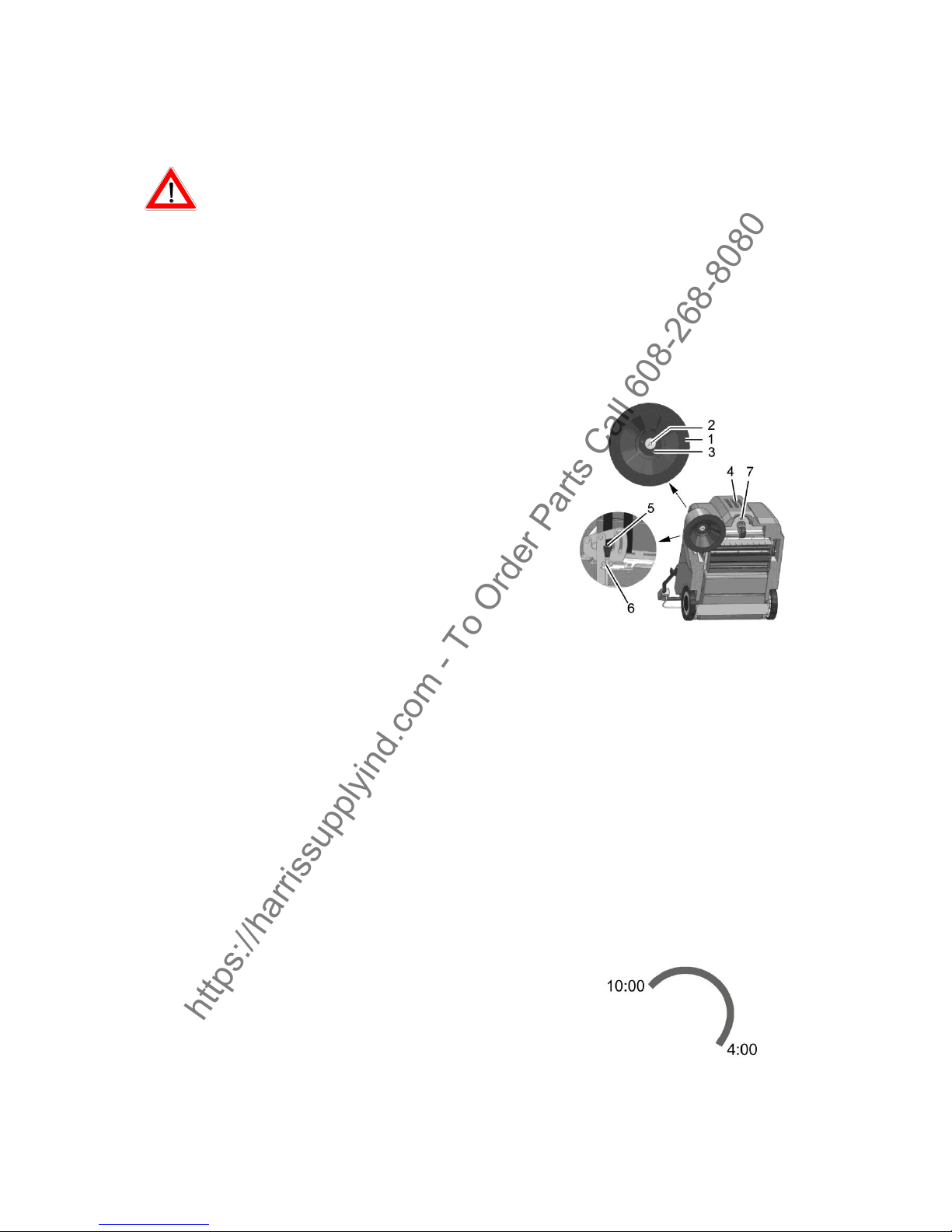
5.3 Side brushes
1. Side brushes
2. Wing bolt
3. Carrier
4. Hood
5. Adjusting bolt
6. Counternut
7. Locking bolt
5.3.1 Changing the side brush
Check the side brush (Fig. 8/1) weekly and change in the case of wear.
1. Switch the machine off and lay it on its side.
2. Remove the wing bolt (Fig. 8/2) with the washer from underneath the side brush
(Fig. 8/1).
3. Pull the side brush off.
4. To fix the side brush align the drive pins on the side brush drive plate and secure with the wing bolt
and washer supplied.
5.3.2 Setting the sweeping pattern
In the case of brush wear and after changing the
side brush (Fig. 8/1), readjust the sweeping
pattern.
1. Switch the machine off; unscrew the locking
bolt (Fig. 8/7) and open the hood (Fig. 8/4).
2. Loosen the counternut (Fig. 8/6) and adjust
the sweeping pattern by turning the adjusting
bolt (Fig. 8/5) clockwise and counter
clockwise so that it touches the floor.
3. Tighten the counternut again and close the
hood.
4. Switch the machine on and allow the side
brush to run while standing still for a short
time.
5. Switch the machine off, raise the front a little
and pull it back.
6. Check the sweeping pattern, comparing it
with a clock viewed driving forward.
When set correctly, the sweeping pattern
must make an impression on the floor
between approx. 10:00 and 4:00 o' clock.
7. Repeat the process, if necessary, until the
sweeping pattern is set correctly.
https://harrissupplyind.com - To Order Parts Call 608-268-8080
Page 15

15
8. Close the hood (Fig. 8/4) and screw the
locking bolt (Fig. 8/7) back in.
5.4 Rotary brush
1. Rotary brush
2. Fillister head self-tapping screws
3. Rotary brush segment
4. Sealing strips
5. Sweeping pattern adjusting lever
6. Timing belt
7. Hood
8. Locking bolt
Fig 9
5.4.1 Cleaning the brush space
The brush space with rotary brush (Fig. 9/1) and
gaskets (Fig. 9/4) must be checked daily for
signs of dirt and cleaned, if necessary.
5.4.2 Changing the rotary brush
The rotary brush (Fig. 9/1) must be checked
weekly and changed in the case of wear.
1. Switch the machine off and lay it on its side.
2. Loosen the six fillister head screws (Fig. 9/2)
in the rotary brush and remove the two roller
segments.
3. Install the two new roller segments and fix in
place with the fillister head screws.
4. After changing the rotary brush, readjust the
sweeping pattern as necessary.
5.4.3 Setting the sweeping pattern
In the case of brush wear, and after changing the
rotary brush (Fig. 9/1), readjust the sweeping
pattern.
1. Switch the machine off, unscrew the locking
bolt (Fig. 9/8) and open the hood (Fig. 9/7).
2. Loosen the wing nut on the adjusting lever
(Fig. 9/5) and adjust the sweeping pattern
using the adjusting lever by pivoting it up and
down until it touches the floor.
3. Tighten the wing nut again and close the
hood.
4. Switch the machine on and allow the rotary
brush to run while standing still for a short
time.
5. Switch the machine off, raise the front a little
and pull it back.
6. When adjusted correctly, there must be an
approx. 50 mm wide sweeping pattern on the
floor which has parallel sides.
7. Repeat the process, if necessary, until the
sweeping pattern is set correctly.
8. Close the hood (Fig. 9/7) and screw the
locking bolt (Fig. 9/8) back in
5.4.4 Changing the sealing strips
The four sealing strips (Fig. 9/4) must
be checked weekly and changed in the
case of wear.
1. Switch the machine off and lay it on
its side.
2. Remove all four sealing strips (Fig.
9/2) with holders.
3. Loosen the screws in the holders
and remove the damaged sealing
strips.
4. Fix the new sealing strips on the
holders and reinstall them.
5. Adjust the sealing strips so that they
touch the floor lightly.
https://harrissupplyind.com - To Order Parts Call 608-268-8080
Page 16

16
5.4.5 Changing the timing belt
The timing belt (Fig. 9/6) must be
checked every 500 operating hours and
changed in the event of wear.
1. Switch the machine off, unscrew the
locking bolt (Fig. 9/8) and open the
hood (Fig. 9/7).
2. Slacken the timing belt (Fig. 9/6) using
the tension pulley and remove
the belt.
3. Slacken the tension pulley and install
the new timing belt. The timing belt is
automatically tensioned by means of
a tension spring.
4. Close the hood (Fig. 9/7) and screw
the locking bolts (Fig. 9/8) back in.
5.5 Debris container
1 Debris container
2 Locking mechanism
3 Seal
4 Handle
Fig. 10
5.5.1 Emptying the debris container
Check the fill level of the debris container (Fig.
10/1) at regular intervals (max. load capacity 25
kg) and empty as necessary.
1. Switch the machine off and pull the locking
mechanism (Fig. 10/2) on the debris
container (Fig. 10/1) upwards.
2. Pull the debris container to the rear out of the
machine using the handle (Fig. 10/4) and
dispose of the waste according to the
applicable environmental laws.
3. Reinstall the debris container and press it
against the locking mechanism until it audibly
latches into place.
5.5.2 Changing the seal
Check the seal (Fig. 10/3) weekly for signs of
wear and change it as necessary.
1. Switch off the machine and pull the locking
mechanism (Fig. 10/2) on the debris
container (Fig. 10/1) upwards.
2. Pull the debris container (Fig. 10/3) to the
rear and out of the machine using the handle
(Fig. 10/4).
3. Pull the seal for the debris container from the
filter support frame. Install a new seal.
4. Reinstall the debris container and press it
against the locking mechanism until it audibly
latches into place
5.6 Dust vacuum
1 Filter
2 Sealing strip
3 Filter support frame
4 Shaking device
5 Wing bolts
6 Holders
Fig. 11
https://harrissupplyind.com - To Order Parts Call 608-268-8080
Page 17

17
5.6.1 Cleaning the filter
Clean the filter (Fig. 11/1) in the dust vacuum as
necessary using the shaking device (Fig. 11/4).
In the case of extreme accumulation of dirt, clean
the filter as follows:
1. Switch the machine off and remove the
debris container.
2. Loosen the wing bolts (Fig. 11/5). Pivot the
filter support frame (Fig. 11/ 3) down and
remove it.
3. Remove the filter from the filter support
frame.
Beat the filter clean or use a vacuum cleaner.
Be careful not to damage the filter ribs!
4. Insert the correct side of filter in the filter
support frame. The sealing strip (Fig. 11/2)
must point towards the suction turbine!
5. Hook the filter support frame in the holder
(Fig. 11/6) and fix in place with the wing
bolts.
6. Reinstall the debris container
5.6.2 Changing the filter
Check the filter (Fig. 11/1) every 250 operating
hours for signs of wear and change it as
necessary.
1. Switch the machine off and remove the
debris container.
2. Unscrew the wing bolts (Fig. 11/5). Pivot the
filter support frame (Fig. 11/3) down and
remove it.
3. Remove the filter from the filter support
frame.
4. Insert the correct side of the new filter in the
filter support frame. The sealing strip (Fig.
11/2) must point towards the suction turbine!
5. Hook the filter support frame in the holder
(Fig. 11/6), if necessary, and fix in place with
the wing bolts.
6. Reinstall the debris container
5.6.3 Install the Lint filter
If the machine is mainly used on carpet, you
have to install the lint filter (7).
1. Switch the machine off and remove the
debris container.
2. Unscrew the wing bolts (Fig.11/5). Pivot the
filter support frame (3) down and remove it.
3. Mount the lint filter (7) between filter and the
filter support frame
4. Hook the filter support frame in the holder
(Fig.11/6), if necessary, and fix in place with
the wing bolts.
5. Reinstall the debris container.
Noise emission value
The sound pressure level (LpA) (at the ear of the
operator) measured according to DIN IEC 603352-72 under normal working conditions: 70 dB (A)
Measurement inaccuracy (KpA): 2 dB (A)
EC Declaration of Conformity (corresponds to
EC Directive 2006/42/EC)
Tornado Industries declares that the products
Tornado SWB 26/8
to which this declaration relates, conform
to the relevant provisions of the
safety and health requirements stipulated
in EC Directive 2006/42/EC and is in
accordance with 2004/108/EC.
Reference was made to the following standards
and/or norms and/or technical specifications to
ensure proper implementation of the safety and
health requirements in the EC Directive:
EN 60335-2-72
EN 55012
EN 61000-6-2
https://harrissupplyind.com - To Order Parts Call 608-268-8080
 Loading...