

Page 1
WIRING INSTRUCTIONS: WOS-M
1. Turn power off at the electrical panel.
2. Connect the sensor black wire to line. Connect the sensor red wire to the load.
3. Connect the green wire to the ground. Unit must be properly grounded to operate correctly.
4. Mount the sensor to the electrical box using 2 mounting screws provided.
5. Install wall plate.
6. Turn power on at the electrical panel.
7. Program only if custom setting is desired. Refer to push button chart and follow FOUR & OUT THE
DOOR instructions.
INSTALLATION INSTRUCTIONS
DESCRIPTION
The WOS Series is a line voltage powered wall switch occupancy sensor.
They turn lighting systems on and off based on occupancy. The sensor is
configured to turn lighting on, and hold it on as long as the sensor detects
people moving in the room. After no movement is detected for a user
specified set time (5 to 30 minutes), the lights are switched off.
Optional energy savings features are included. The "walk-through" mode
shortens turn-off timing to 3 minutes when no activity is detected after 30
seconds. An integral light sensor can keep lights off if sufficient daylight is
present in the room.*
*WOS-SN no light sensor
SPECIFICATIONS
VOLTAGE: 120/230/277 VAC
WOS-SN: 120 VAC Only
OPERATING TEMPERATURE: 32°to 131°F (0°to 55°C)
ADJUSTABLE TIME DELAY: 5 minutes - 30 minutes (software settable)
WALK-THROUGH MODE: 3 minutes if no activity after 30 seconds
(software settable)
TEST MODE: Software setting
PIR COVERAGE: SENSITIVITY ADJUSTMENT - Software settable
COVERAGE: 1200 sq. ft. PIR
*WOS-SN VOLTAGE: 120 VAC Only
*WOS-MN2T COVERAGE: 1200 sq. ft. PIR and 400 sq. ft. Ultrasonic
LI-959(A)
FOR TECHNICAL SUPPORT: techsupport@nsiindustries.com 888.500.4598
WOS Series
PLACEMENT GUIDELINES
The sensor should be installed with a visually unobstructed view of the workspace normally
occupied. If the occupant cannot see the sensor from their normal work position, the sensor will
not be able to detect their presence. File cabinets, doors, partitions, and walls are typical types
of obstructions.
Avoid sensor placement with a view through a doorway. If doorway view is unavoidable, set
sensor to manual move (vacancy setting) with Function 6. If hallway movement trips ultrasonic
sensor, set to PIR only for initial trigger (Function 10 For WOS-MN2T Only).
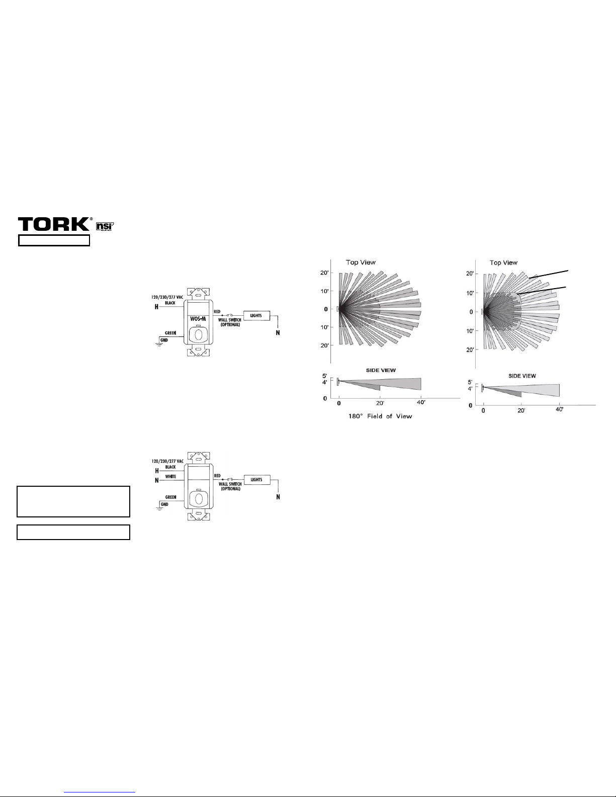
COVERAGE PATTERN: WOS-MN2T
The WOS-MN2T Series provides a pattern of 1200 square feet with the PIR. The diagram shows
the motion detection area with small motion detection closer to the sensor. Barriers within the
space that block line-of-sight to PIR sensor detection will decrease coverage area. Workspace
area should be placed to fall within the Ultrasonic coverage area.
WARNING
Unit must be properly grounded to operate correctly.
WIRING INSTRUCTIONS: WOS-MN, WOS-SN, WOS-MN2T
1. Turn power off at the electrical panel.
2. Connect the sensor black wire to line. Connect the sensor white wire to neutral. Connect the sensor red
wire to the load.
3. Connect your system grounding wire to the green screw on the sensor. Unit must be properly grounded
per local codes.
4. Mount the sensor to the electrical box using 2 mounting screws provided.
5. Install wall plate.
6. Turn power on at the electrical panel.
7. Program only if custom setting is desired. Refer to push button chart and follow FOUR & OUT THE
DOOR instructions.
COVERAGE PATTERN: WOS-M, WOS-MN, WOS-SN
The WOS Series provides a pattern of 1200 square feet. The diagram shows the motion detection
area with small motion detection closer to the sensor. Barriers within the space that block line-ofsight to sensor detection will decrease coverage area.
WOS-M
WOS-MN
WOS-SN
WOS-MN2T
PIR Sensor
PIR Sensor
PIR Sensor
PIR and Ultrasonic Sensor
*WOS-SN 120 VAC only
*
PIR Coverage
Ultrasonic Coverage
CAUTION
We recommend that installation be made by a liscensed electrician.
Before wiring and servicing, power to this unit and the
equipment it controls must be turned off at the main panel. Connect in
accordance with national and local electrical codes.
Page 2

LI-959(A)
EXAMPLE:
To change time delay from 5 min to 10 min:
1. START Press the button 5 times.
a. The LED is now on.
2. CHOOSE Press the button the number of times for the mode you wish to change.
a. Press the button 1 time for Function 1.
b. The sensor now flashes twice, pauses, flashes twice, pauses, etc.
(This shows the current program)
3. CHANGE Press the button 1 time.
a. The sensor now flashes once, pauses, flashes once, pauses, etc.
(This shows the new program setting)
4. SAVE Now press and hold the button for 5 seconds.
a. The LED is now on
b. Now press the button 5 times
c. The time delay is changed to 5 minutes
NOTE: To exit programming without making a change, if no button is pressed for 30 sec the
sensor will return to run mode with the last settings that were locked in.
FOUR & OUT THE DOOR SETTINGS CHANGE
To change a program feature:
PREP: Review the function to see the function number, current setting and new setting that is
to be entered.
1. START program mode:
a. Press the button 5 times consecutively. (The LED flashes with each press)
NOTE: After the 5th button press the LED will stay on. The sensor is now in Program Mode.
2. CHOOSE the function:
a. Press the button "X" number of times to enter a function to change. (The LED
flashes with each press)
NOTE: When the button presses stop the sensor will then flash back the current setting for
that function. (The sensor will do this 10 times and then go back to run mode if nothing is
processed with prior settings)
3. CHANGE Function:
a. Press the button the number of times for the new setting. (The LED flashes
with each press)
NOTE: When the button presses stop, the sensor will then flash back the new setting for
that function. (The sensor will do this 10 times and then go back to run mode if nothing is
pressed and the new setting will not be saved)
4. SAVE Setting
a. Press and hold the button until the LED stays on, then release the button.
b. Press the button 5 times to lock in the setting. (The LED flashes with each press)
After the 5th press the sensor will go back to run mode with the new setting active.
FOR TECHNICAL SUPPORT: techsupport@nsiindustries.com 888.500.4598
INSTALLATION INSTRUCTIONS
PUSH BUTTON FUNCTION CHART
Function 1 - Time Delay
1. 10 min*
2. 5 min
3. 15 min
4. 20 min
5. 25 min
6. 30 min
Function 2 - Ultrasonic Coverage
(For WOS-MN2T Only)
1. Large Area*
2. Medium Area
3. Small Area
Function 3 - Photocell Set Point Ones
Digit
(Not WOS-SN)
1. Disabled*
2. 2 fc
3. 3 fc
4. 4 fc
5. 5 fc
6. 6 fc
7. 7 fc
8. 8 fc
9. 9 fc
10. 0 fc
Function 4 - Photocell Set Point Tens
Digit
(Not WOS-SN)
1. 0 fc*
2. 10 fc
3. 20 fc
4. 30 fc
5. 40 fc
6. 50 fc
7. 60 fc
8. 70 fc
9. 80 fc
10. 90 fc
11. 100 fc
12. 200 fc
Function 5 - PIR Coverage
1. Large Area*
2. Small Area
Function 6 - Mode
1. Auto On/Off*
2. Manual On/Auto Off (Vacancy)
3. Walk Through
4. Test Mode (if left in test mode for
30 min, revert to default settings)
Function 7 - Push Button Disable
1. Button Active*
2. Button Disabled
Function 8 - 100 Hour Burn-In
1. Disabled *
2. Enabled
Function 9 - Warning Flash before shut off
1. Disabled*
2. Enabled
Function 10 - Initial Turn On Sensor Trigger
(For WOS-MN2T Only)
1. PIR and Ultrasound*
2. Ultrasound Only
3. PIR Only
Function 11 - Maintain On Sensor Trigger
(For WOS-MN2T Only)
1. Either PIR or Ultrasound*
2. Ultrasound Only
3. PIR Only
Function 15 - Factory Defaults
1. Disabled*
2. Enabled
*Default Settings
Page 3

INSTRUCTIONS DE CÂBLAGE: WOS-M
1. Coupez l’alimentation électrique au panneau électrique.
2. Connectez le fil noir du détecteur à la ligne. Connectez le fil rouge du détecteur à la charge.
3. Connectez le fil vert à la masse. L’appareil doit être correctement mis à la terre pour fonctionner
correctement.
4. Montez le détecteur à la boîte électrique au moyen des 2 vis de montage fournies.
5. Installez la plaque murale.
6. Rallumez l’alimentation électrique au panneau électrique.
7. Programmez seulement si vous voulez un réglage personnalisé. Reportez-vous au diagramme des
boutons-poussoirs et suivez les instructions FOUR & OUT THE DOOR.
INSTRUCTIONS D'INSTALLATION
DESCRIPTION
La série WOS est une ligne de détecteurs de présence à commutateur mural
alimentés sur secteur. Ils activent et désactivent les systèmes d’éclairage
selon la présence. Le détecteur est configuré pour activer l’éclairage et le
maintenir actif aussi longtemps que le détecteur détecte des personnes se
déplaçant dans la pièce. Lorsqu’aucun mouvement n’est détecté pendant un
délai de consigne spécifié par l’utilisateur (de 5 à 30 minutes), les lumières
sont éteintes.
Des fonctionnalités d’économie d’énergie facultatives sont incluses. Le mode
« traversant » réduit la temporisation à 3 minutes si aucune activité n’est
détectée après 30 secondes. Un détecteur de lumière intégré peut maintenir
les lumières éteintes si suffisamment de lumière du jour est présente dans
la pièce.*
*WOS-SN pas de capteur de lumière
CARACTÉRISTIQUES
TENSION: 120/230/277 V c.a.
WOS-SN: 120 V c.a. seulemente
TEMPÉRATURE DE FONCTIONNEMENT: De 32 à 131°F (de 0 à 55°C)
TEMPORISATION RÉGLABLE: De 5 minutes à 30 minutes (réglage
logiciel)
MODE TRAVERSANT : 3 minutes après 30 secondes d'inactivité (réglage
logiciel)
MODE D’ESSAI: Réglage logiciel
COUVERTURE IRP: RÉGLAGE DE LA SENSIBILITÉ – Réglage logiciel
COUVERTURE: 1200 pieds carrés
*WOS-SN TENSION: 120 V c.a. seulemente
*WOS-MN2T COUVERTURE: 1200 pieds carrés IRP et pieds carrés
Ultrasonique
LI-959(A)
SOUTIEN TECHNIQUE: techsupport@nsiindustries.com 888.500.4598
WOS SÉRIE
DIRECTIVES DE PLACEMENT
Le détecteur doit être installé avec une vue sans entrave de l’espace de travail normalement
occupé. Si l’occupant ne peut pas voir le détecteur depuis sa position de travail habituelle, le
détecteur ne sera pas en mesure de détecter sa présence. Les classeurs, les portes, les cloisons ou
les murs sont des obstacles typiques.
Évitez de placer le détecteur avec la vue sur une entrée de porte. Si la vue d'une entrée de
porte est inévitable, réglez le détecteur sur mouvement manuel (réglage pièce libre) avec la
Fonction 6. Si le mouvement de couloir voyages capteur ultrasonique, mis à IRP seulement pour
déclenchement initial (Function 10 WOS-MN2T Seulemente).
MODÈLE DE COUVERTURE: WOS-MN2T
La série WOS-MN2T fournit un modèle de 1200 pieds carrés avec l’IRP. Le diagramme montre la
zone de détection de mouvement avec détection de mouvement petit plus près de la sonde. Les
obstacles dans l'espace qui bloquent la ligne de mire de détection du capteur IRP diminueront
zone de couverture. Espace de travail devrait être mis à tomber dans la zone de couverture
ultrasons.
AVERTISSEMENT
L’appareil doit être correctement mis à la terre pour fonctionner correcte-
ment.
INSTRUCTIONS DE CÂBLAGE: WOS-MN, WOS-SN, WOS-MN2T
1. Coupez l’alimentation électrique au panneau électrique.
2. Connectez le fil noir du détecteur à la ligne. Connectez le fil blanc du détecteur au neutre. Connectez le
fil rouge du détecteur à la charge.
3. Connectez le fil vert à la masse. L’appareil doit être correctement mis à la terre pour fonctionner
correctement.
4. Montez le détecteur à la boîte électrique au moyen des 2 vis de montage fournies.
5. Installez la plaque murale.
6. Rallumez l’alimentation électrique au panneau électrique.
7. Programmez seulement si vous voulez un réglage personnalisé. Reportez-vous au diagramme des
boutons-poussoirs et suivez les instructions FOUR & OUT THE DOOR.
MODÈLE DE COUVERTURE: WOS-M, WOS-MN, WOS-SN
La série WOS-M fournit un modèle de 1200 pieds carrés. Le diagramme montre la zone de
détection de mouvement avec une détection de mouvement réduit plus près du détecteur. Les
obstacles de l’espace qui bloquent la ligne de visée de la détection du détecteur diminueront la
zone de couverture.
WOS-M
WOS-MN
WOS-SN
WOS-MN2T
Capteur IRP
Capteur IRP
Capteur IRP
Capteur de IRP et Ultrasonique
*WOS-SN 120 V c.a. seulemente
LANTERNES
INTERRUPTEUR (OPTION)
VERT
MASSE
NOIR
ROUGE
120/230/277 V. c.a.
WOS-M
LIGNE-HOT
NEUTRE
NOIR
BLANC
ROUGE
LANTERNES
INTERRUPTEUR (OPTION)
VERT
MASSE
LIGNE-HOT
NEUTRE
NEUTRE
120/230/277 V. c.a.*
VUE DE DESSUS
VUE DE CÔTÉ
180° CHAMP DE VUE
VUE DE DESSUS
VUE DE CÔTÉ
IRP Couverture
Couverture Ultrasonic
ATTENTION
Nous recommandons de confier l’installation à un électricien qualifié.
Avant le raccordement et la maintenance, l’alimentation de ce commutateur
doit être coupée au panneau électrique principale. Effectuez les branche-
ments conformément aux codes de l’électricité en vigueur dans votre pays
et votre région.
Page 4

LI-959(A)
EXEMPLE:
Pour modifier la temporisation de 5 min à 10 min:
1. DÉMARRER Appuyez sur le bouton 5 fois.
a. La DEL est maintenant allumée.
2. CHOISIR Appuyez sur le bouton le nombre de fois correspondant pour accéder au mode à
changer
a. Appuyez sur le bouton 1 fois pour la Fonction 1
b. Le détecteur clignotera maintenant deux fois, fera une pause, clignotera deux fois, fera
une pause et ainsi de suite.
(Cela montre le programme actuel)
3. MODIFIER Appuyez sur le bouton 1 fois.
a.Le détecteur clignotera maintenant une fois, fera une pause, clignotera une fois, fera une
pause et ainsi de suite.
(Cela montre le nouveau réglage du programme).
4. ENREGISTRER Appuyez sur et maintenez enfoncé le bouton pendant 5 secondes.
a. La DEL est maintenant allumée
b. Maintenant, appuyez sur le bouton 5 fois
c. La temporisation est changée à 5 minutes
REMARQUE: Pour quitter la programmation sans effectuer de changements, si aucun bouton
n’est appuyé pendant 30 secondes, le détecteur reviendra au mode de fonctionnement avec les
derniers paramètres enregistrés.
Modification des paramètres FOUR & OUT THE DOOR
Pour modifier une fonctionnalité du programme:
PRÉPARATION: Revoyez la fonction pour voir le numéro de la fonction, le réglage actuel et
le nouveau réglage à introduire.
1. LANCER le mode de programmation:
a. Appuyez sur le bouton 5 fois de suite (la DEL clignote à chaque pression)
REMARQUE : Après la 5ème pression du bouton, la DEL restera allumée. Le détecteur est
maintenant en mode de programmation
2. CHOISIR la fonction:
a. Appuyez sur le bouton "X" fois pour accéder à une fonction à modifier (la DEL clignote
à chaque pression)
REMARQUE : Lorsque les pressions du bouton s’arrêtent, le détecteur fera alors clignoter le
réglage actuel pour cette fonction (le détecteur fera cela 10 fois, puis reviendra au mode
de fonctionnement avec les paramètres précédents si aucun bouton n'est appuyé)
3. MODFIER la fonction:
a. Appuyez sur le bouton le nombre de fois correspondant pour le nouveau réglage. (La
DEL clignote à chaque pression)
REMARQUE : Lorsque les pressions du bouton s’arrêtent, le détecteur fera alors clignoter
le nouveau réglage pour cette fonction. (Le détecteur fera cela 10 fois, puis reviendra au
mode de fonctionnement si aucun bouton n'est appuyé et le nouveau réglage ne sera pas
enregistré)
4. ÉCONOMIE réglage
a. Appuyez et maintenez enfoncé le bouton jusqu’à ce que la DEL reste allumée, puis
relâchez le bouton
b. Appuyez sur le bouton 5 fois pour verrouiller le réglage (la DEL clignote à chaque
pression) Après la 5ème pression le détecteur reviendra au mode de fonctionnement avec
le nouveau réglage actif.
SOUTIEN TECHNIQUE: techsupport@nsiindustries.com 888.500.4598
INSTALLATION INSTRUCTIONS
DIAGRAMME DE FONCTIONS DES BOUTONS-POUSSOIRS
Fonction 1 - Temporisation
1. 10 min*
2. 5 min
3. 15 min
4. 20 min
5. 25 min
6. 30 min
Fonction 2 - Sensibilité à ultrasonique
(WOS-MN2T Seulement)
1. Grande zone*
2. Moyenne zone
3. Petite zone
Fonction 3 - Chiffre des unités du point
de consigne des cellules photoélectriques
(Pas WOS-SN)
1. Désactivée*
2. 2 fc
3. 3 fc
4. 4 fc
5. 5 fc
6. 6 fc
7. 7 fc
8. 8 fc
9. 9 fc
10. 0 fc
Fonction 4 - Chiffre des dizaines du point
de consigne des cellules photoélectriques
(Pas WOS-SN)
1. 0 fc*
2. 10 fc
3. 20 fc
4. 30 fc
5. 40 fc
6. 50 fc
7. 60 fc
8. 70 fc
9. 80 fc
10. 90 fc
11. 100 fc
12. 200 fc
Fonction 5 - Sensibilité à IRP
1. Grande surface*
2. Petite surface
Fonction 6 - Mode
1. Activation/Désactivation
automatique *
2. Activation manuelle/Désactivation
automatique
3. Traversant
4. Mode d’essai (s’il est laissé en
mode d’essai pendant 30 min,
il reviendra aux paramètres par
défaut)
Fonction 7 - Désactiver le bouton-poussoir
1. Bouton actif*
2. Bouton désactivé
Fonction 8 - 100 heures de fonctionnement
1. Désactivée *
2. Activée
Fonction 9 - Clignotement d’avertissement
avant l’arrêt
1. Désactivée*
2. Activée
Fonction 10 - Initiale tour sur capteur de
déclenchement
(WOS-MN2T Seulement)
1. IRP et ultrasons*
2. Ultrasons seulement
3. IRP seulement
Fonction 11 - Maintenir sur le capteur de
déclenchement
(WOS-MN2T Seulement)
1. IRP ou ultrasons*
2. Ultrasons seulement
3. IRP seulement
Fonction 15 - Paramètres par défaut
1. Désactivée*
2. Activée
*Paramètres par défaut
Page 5

INSTRUCCIONES DE CABLEADO: WOS-M
1. Apague la corriente en el panel eléctrico.
2. Conecte el cable negro del sensor a la línea. Conecte el cable rojo del sensor a la carga.
3. Conecte el cable verde a tierra. La unidad debe estar conectada a tierra debidamente para funcionar
correctamente.
4. Monte el sensor en la caja eléctrica usando los 2 tornillos de montaje provistos.
5. Instale la placa de pared.
6. Encienda la corriente en el panel eléctrico.
7. Programe solo si se desea un ajuste personalizado. Remítase a la tabla de botones y siga las
instrucciones CUATRO Y SALIDA.
INSTRUCCIONES DE INSTALACIÓN
DESCRIPTION
El WOS es un sensor de ocupación con interruptor de pared que funciona con
voltaje de línea. Enciende y apaga los sistemas de iluminación basándose
en la ocupación. El sensor está configurado para encender las luces, y
mantenerlas encendidas mientras el sensor detecte que hay gente circulando
en el cuarto. Después de que no se detecte movimiento por un tiempo
especificado por el usuario (5 a 30 minutos), se apagan las luces.
Se incluyen funciones opcionales para ahorrar energía. El modo “walkthrough” [recorrido] abrevia el tiempo a 3 minutos cuando no se detecta
actividad después de 30 segundos. Un sensor integral de luz puede
mantener las luces apagadas si hay suficiente en el cuarto.*
*WOS-SN sin sensor de luz
ESPECIFICACIONES
VOLTAJE: 120/230/277 VCA
WOS-SN: 120 VCA Only
TEMPERATURA OPERATIVA: 32° a 131°F (0°a 55°C)
RETARDO DE TIEMPO AJUSTABLE: 5 minutos - 30 minutos (fijable
mediante software)
MODO RECORRIDO: 3 minutos si no hay actividad después de 30
segundos (fijable mediante software)
MODO PRUEBA: Ajuste mediante software
COBERTURA PIR: AJUSTE DE SENSIBILIDAD - Fijable mediante software
COBERTURA: 1200 pies2 PIR
*WOS-SN VOLTAJE: 120 VCA solamente
*WOS-MN2T COBERTURA: 1200 pies2 PIR y 400 pies2 Ultrasónico
LI-959(A)
PARA ASISTENCIA TÉCNICA: techsupport@nsiindustries.com 888.500.4598
WOS SERIE
PAUTAS DE COLOCACIÓN
Debe instalarse el sensor con una vista sin obstrucciones del espacio de trabajo que se ocupa
normalmente. Si el ocupante no puede ver el sensor desde su posición normal de trabajo, el
sensor no podrá detectar su presencia. Los muebles de archivo, puertas, particiones o paredes
son tipos comunes de obstrucciones.
Evite colocar el sensor con vista a través de un umbral. Si no se puede evitar la vista a través
de un umbral, fije el sensor en movimiento manual (ajuste vacante) con la función 6. Si el
movimiento en el pasillo dispara el sensor ultrasónico fije en Solo PIR para disparo inicial
(Función 10 Para WOS-MN2T Solamente).
PATRÓN DE COBERTURA: WOS-MN2T
La serie WOS-MN2T proporciona un patrón de 1200 pies cuadrados con PIR. El diagrama
muestra el área que tiene detección de movimiento con la detección de poco movimiento más
cerca del sensor. Las barreras que haya dentro del espacio que bloqueen la línea de visión
detectora del sensor PIR disminuyen el área de cobertura. Área de trabajo debe ser colocado a
caer dentro del área de cobertura de ultrasonidos..
ADVERTENCIA
La unidad debe estar conectada a tierra debidamente para funcionar
correctamente.
INSTRUCCIONES DE CABLEADO: WOS-MN, WOS-SN, WOS-MN2T
1. Apague la corriente en el panel eléctrico.
2. Conecte el cable negro del sensor a la línea. Conecte el cable blanco del sensor a la posición neutral.
Conecte el cable rojo del sensor a la carga.
3. Conecte el cable verde a tierra. La unidad debe estar conectada a tierra debidamente para funcionar
correctamente.
4. Monte el sensor en la caja eléctrica usando los 2 tornillos de montaje provistos.
5. Instale la placa de pared.
6. Encienda la corriente en el panel eléctrico.
7. Programe solo si se desea un ajuste personalizado. Remítase a la tabla de botones y siga las
instrucciones CUATRO Y SALIDA.
PATRÓN DE COBERTURA: WOS-M, WOS-MN, WOS-SN
La serie WOS proporciona un patrón de 1200 pies cuadrados. El diagrama muestra el área
que tiene detección de movimiento con la detección de poco movimiento más cerca del sensor.
Las barreras que haya dentro del espacio que bloqueen la línea de visión detectora del sensor
disminuyen el área de cobertura.
WOS-M
WOS-MN
WOS-SN
WOS-MN2T
Sensor PIR
Sensor PIR
Sensor PIR
Sensor PIR y Ultrasónico
*WOS-SN 120 VCA solamente
120/230/277 VCA
NEGRO
VERDE
TERRENO
INTERRUPTOR DE LA
PARED (OPCIONAL)
ROJO
LUCES
NEUTRAL
LÍNEA-HOT
WOS-M
120/230/277 VCA*
NEGRO
BLANCO
LÍNEA-HOT
NEUTRAL
NEUTRAL
LUCES
INTERRUPTOR DE LA
PARED (OPCIONAL)
ROJO
VERDE
TERRENO
VISTA DESDE ARRIBA
VISTA LATERAL
180° CAMPO DE VISIÓN
VISTA LATERAL
VISTA DESDE ARRIBA
Cobertura Ultrasonic
Cobertura PIR
PRECAUCIÓN
Se recomienda que la instalación sea realizada por un electricista
calificado. Antes de cablear y dar servicio, debe apagarse la corriente
a este interruptor en el panel principal. Conecte de acuerdo con los
códigos eléctricos locales y nacionales.
Page 6

LI-959(A)
PARA ASISTENCIA TÉCNICA: techsupport@nsiindustries.com 888.500.4598
INSTRUCCIONES DE INSTALACIÓN
TABLE DE FUNCIONES DE LOS BOTONES
Función 1 - Retardo de tiempo
1. 10 min*
2. 5 min
3. 15 min
4. 20 min
5. 25 min
6. 30 min
Función 2 - Cobertura Ultrasónico
(Para WOS-MN2T Solamente)
1. Área grande*
2. Área medio
3. Área pequeña
Función 3 - Queridos dígitos puntos de
ajuste fotocélula
(No WOS-SN)
1. Desactivado*
2. 2 fc
3. 3 fc
4. 4 fc
5. 5 fc
6. 6 fc
7. 7 fc
8. 8 fc
9. 9 fc
10. 0 fc
Función 4 - Decenas digitos puntos de
ajuste fotocélula
(No WOS-SN)
1. 0 fc*
2. 10 fc
3. 20 fc
4. 30 fc
5. 40 fc
6. 50 fc
7. 60 fc
8. 70 fc
9. 80 fc
10. 90 fc
11. 100 fc
12. 200 fc
Función 5 - Cobertura de PIR
1. Área grande*
2. Área pequeña
Función 6 - Modo
1. Enc/apag autom*
2. No se usa
3. Recorrido
4. Modo prueba (Si queda en modo
de prueba por 30 min, revierte a
los ajustes predeterminados)
Función 7 - Pulsador Desactivar
1. Botón activo*
2. Botón deshabilitado
Función 8 - 100 horas marcar a fuego
1. Desactivado *
2. Habilitado
Función 9 - Advertencia del flash antes
apagado
1. Desactivado *
2. Habilitado
Función 10 - Gatillo de inicial sensor activar
(Para WOS-MN2T Solamente)
1. PIR y Ultrasónico*
2. Ultrasound Solamente
3. PIR Solamente
Función 11 - Mantener el gatillo sensor
(For WOS-MN2T Only)
1. PIR o Ultrasónico*
2. Ultrasónico Solamente
3. PIR Solamente
Función 15 - Ajustes predeterminados de
fábrica
1. Desactivado*
2. Habilitado
*Ajustes predeterminados de fábrica
CAMBIO DE AJUSTES CUATRO Y SALIDA
Para cambiar la función de un programa:
PREP: Revise la función para ver el número de la función, el ajuste de corriente y el nuevo
ajuste que debe colocarse.
1. INICIAR el modo de programa:
a. Presione el botón 5 veces consecutivas (Destella el LED cada vez que presione)
NOTA: Después de la 5a vez que presione el botón, el LED permanece encendido. El sensor
ahora está en el Modo Programa.
2. ELEGIR la función:
a. Presione el botón “X” número de veces para introducir una función a cambiar
(Destella el LED cada vez que presione)
NOTA: Cuando ya no presione más, el sensor destella con el ajuste actual para esa función
(El sensor hace esto 10 veces y luego vuelve al modo para funcionar si no se presiona
nada con los ajustes anteriores)
3. CAMBIAR la función:
a. Presione el botón el número de veces que desee para el nuevo ajuste. (El
LED destella cada vez que presione)
NOTA: Cuando se deja de presionar, el sensor destella con el nuevo ajuste para esa
función. (El sensor hace esto 10 veces y luego vuelve al modo para funcionar si no se
presiona nada y no se guarda el ajuste nuevo)
4. GUARDAR el ajuste:
a. Presione y mantenga así el botón hasta que quede encendido el LED, luego
suelte el botón.
b. Presione el botón 5 veces para fijar el ajuste (El LED destella cada vez que
presione) Después de la 5a vez que presione, el sensor vuelve al modo para funcionar
quedando activo el nuevo ajuste.
EJEMPLO:
Para cambiar el retardo de tiempo de 5 min a 10 min:
1. INCIAR Presione el botón 5 vecees.
a. Ahora queda encendido el LED.
2. ELEGIR Presione el botón el número de veces para el modo que desea cambiar.
a. Presione el botón 1 vez para la Función 1.
b. Ahora el sensor destella dos veces, hace una pausa, destella dos veces, hace una pausa, etc.
(Esto muestra el programa actual)
3. CAMBIAR Presione el botón 1 vez.
a. Ahora el sensor destella una vez, hace una pausa, destella una vez, hace una pausa, etc.
(Esto muestra el nuevo ajuste del programa)
4. GUARDAR Ahora presione y mantenga así el botón durante 5 segundos .
a. Ahora queda encendido el LED
b. Ahora presione el botón 5 veces
c. El tiempo de retardo cambia 5 minutos
NOTA: Para salir de la programación sin hacer un cambio, si no se presiona ningún botón durante 30
segundos, el sensor regresará al modo para funcionar con los últimos ajustes que se fijaron.
 Loading...