

Page 1

valve & automation
TREAE SERIES
ELECTRICAL ACTUATOR
USER MANUAL
NOVEMBER / 2018
PLEASE READ THE INSTRUCTIONS BEFORE USE
www.smstork.com
Page 2

CONTENT
1. PURPOSE OF DOCUMENT ....................................................................................................................................................3
2. PRODUCT OVERVIEW ............................................................................................................................................................3
a. Intended Use of the Product ..............................................................................................................................................3
b. Product Coding System .......................................................................................................................................................4
c. Product and Part Pictures ...................................................................................................................................................5
d. Labeling Details ...........................................................................................................................................................................6
3. PRODUCT OPERATION ..........................................................................................................................................................7
a. Storage Conditions ...................................................................................................................................................................7
b. Operation Conditions .............................................................................................................................................................7
4. PRODUCT INSTALLATION ..................................................................................................................................................8
a. Valve Mounting .............................................................................................................................................................................8
b. Manual Working ...........................................................................................................................................................................11
c. Adjusting Cam and Limit Switches .............................................................................................................................12
d. Technical Dimensions ............................................................................................................................................................13
e. Wiring Schemes ........................................................................................................................................................................15
f. Warnings ..........................................................................................................................................................................................17
5. PRODUCT LIFE ..............................................................................................................................................................................17
6. PRODUCT CARE AND MAINTENANCE ..................................................................................................................18
a. Troubleshooting ........................................................................................................................................................................19
7. PRODUCT SPARE PARTS ....................................................................................................................................................19
8. GENERAL CARE, REPAIR AND CLEANING .......................................................................................................20
9. PRODUCT SHIPMENT ...........................................................................................................................................................20
10. WARRANTY CONDITIONS ............................................................................................................................................20
2
SMS-TORK Endüstriyel Otomasyon Ürünleri San. Tic. Ltd. Şti.
Page 3

1. PURPOSE OF DOCUMENT
This document is prepared for showing TORK brand named TREAE series electrical
actuators’ installation, operation and maintenance information.
Security Notifications:
Warning: This sign show personal and product’s security notifications. It warns
user about probably dangers. If cautions are not regarded personal injuring or
product damaged is become unavoidable.
2. PRODUCT OVERVIEW
Electrical actuators are equipment converting electrical power to mechanical power
used for valve control. Electric motor’s torque is transmitted to valve shaft through the
electrical actuator gearbox. This torque makes the valve open or close. Gearbox provides
a steady torque while turning.
TREAE series electric actuators are produced as “On / Off Controlled Electric Actuator “.
Electrical actuators manufactured by SMS-TORK do not use asbestos, PCB, mercury and
other prohibited chemicals.
a. Intended Use of the Product
Electrical actuator is one the most used valve control equipment. The purpose of an
electrical actuator is poening or closing the valve. This opening or closing can be full open/
close or proportional open/close. This can be changed according to process application.
Electrical actuators can be used on ball valve, butterfly valve, plug valve and other proper
valve types.
Advantages of electrical actuators are,
• Electric power is accessible.
• High output torque can be produced with low energy.
• Products have longer life.
• Products are compact and have light weight.
• Sensitive control.
• High protection class.
• Wide power supply range.
• Wide turn angle range.
www.smstork.com
3
Page 4

b. Product Coding System
TREAE XXXX XX XX XX XX
There may not be all the
variations at the product
coding table. For more
details, please contact us.
0200
0300
.....
PROTECTION
CLASS
01 IP 67
02 IP68
03 Explosion Proof
04 IP65
Rotary
Electric
Actuator
Economic
TORQUE
0040
0060
0080
0100
0150
01 230VAC
02 24VDC
03 230VAC/24
VDC Multiboard
02 PROPORTIONAL
SERIES
Tork
OUTPUT
OPERATING
VOLTAGE
CONTROL TYPE
01 ON-OFF
Display)
03 RBU (With Chargeable Battery Unit)
4
SMS-TORK Endüstriyel Otomasyon Ürünleri San. Tic. Ltd. Şti.
OPTIONS
00 NA
01 PIU (With Potentiometer Unit)
02 LCU (Local Control Unit With LCD
Table 1. Product Coding System
Page 5
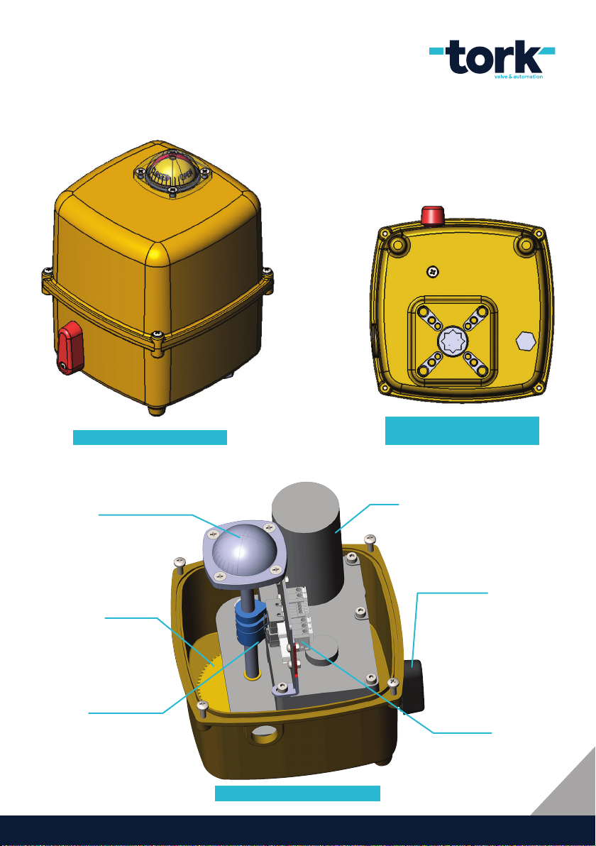
c. Product and Part Pictures
Fig 1. TREAE Electrical Actuator
Fig 2. TREAE Electrical
Actuator Valve Connection Point
Position Indicator
Gear
Cams and Limit
Switches
Fig 3. Electrical Actuator Parts
Motor
Manual Control
Lever
Control Card
5
www.smstork.com
Page 6

d. Labeling Details
Electrical actuators’ general information must be written on their labels. Fig 3 shows a
sample label and the information it contains. For more detailed information, the user
manual, technical support department or sales department can be helpful.
Electrical actuator label contains these informations:
• Model
• Type
• Serial No
• Protection Class
• Ambient Temperature
• Output Torque
• Operation Voltage
• Power
• Operation Time
• Optional Units
Manufactured By Sms-tork Co. Inc.
Model : TREAE006001010100
Type : ON - OFF
Serial No : TREAE60-17-0001
Protection Class : IP67
Ambient Temperature : -20
6
SMS-TORK Endüstriyel Otomasyon Ürünleri San. Tic. Ltd. Şti.
0
C, +600C
Fig 4. Label Details
www.smstork.com
Electric Actuator
Output Torque : 60Nm
Operating Volyage : 230V AC 50Hz
Power : 6W 20 VA
Operation Time : 14 SEC / 90
0
Option :
Page 7

3. PRODUCT OPERATION
When supply voltage (100 - 240 VAC or 24VAC/DC) applied to the electrical actuator,
motor and gearbox produce a rotary force. This force makes the valve acting. According
to this act valve is opened or closed.
a. Storage Conditions
Electrical actuators must be stored in clean, dry and cool ambient. Electrical actuators’
cover screws must be tightened up and cable entries must be closed. When electrical actuators are stored in an open ambient, they must be protected from weather conditions.
b. Operation Conditions
• Small, light and compact design
• On/Off control
• 60 Nm torque value
• High moment with low energy consumption
• Mechanically manual control
• Manual control by electronic card
• 14 sec. opening and closing time
0
• 90
rotation angle
• Torque limiter with current control
• Body Ingress Protection: IP67
• Body Material: Plastic Injection
• Ambient Temperature: -20
• Electric Supply: 100-240VAC, 24VDC, 24VAC
• Limit Switches: 2x OPEN/CLOSE SPDT, 250VAC 3A, 125 VAC 5A
• Aux. Limit Switches : 2x OPEN/CLOSE SPDT, 250VAC 3A, 125 VAC 5A
• Position Indicator : Continuous, as OPEN/CLOSE
• Manual Control: With no 15 switches
• Cable Entrances : M20x1,5
• Greasing : Gear Oil
• Motor operation rate: S4
• Adjustable at different angles
0
C...+700C
www.smstork.com
7
Page 8
4. PRODUCT INSTALLATION
Before installation, it must be checked if there is any damage on the product and
there is any missing part. If there is any damage or missing part, product must not be accepted.
Before the installation inform on the labels and the boxes must be checked.
Before the installation, line voltage and voltage written on the label must be checked
if they are in the same range. Before the installation product’s suitability to the system
must be checked.
Before the installation, the line voltage must be switched OFF. Be careful about
during the installation if anybody can switch it ON. This probability must be prevented
and must be sure about it.
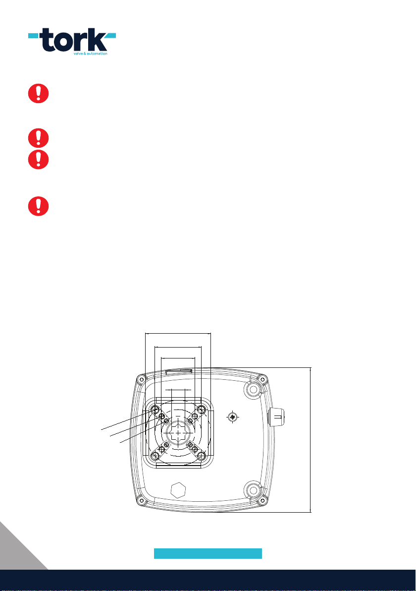
a. Valve Mounting
Electrical actuators are manufactured so that the valve can be mounted according to ISO
5211 standard.
Ø 70
Ø 50
Ø 36
M8
M6
M5
8
SMS-TORK Endüstriyel Otomasyon Ürünleri San. Tic. Ltd. Şti.
14
155
Fig 5. ISO5211 Mounting Surface
Page 9

Fig 6. Valve Mounting
9
www.smstork.com
Page 10

10
SMS-TORK Endüstriyel Otomasyon Ürünleri San. Tic. Ltd. Şti.
Fig 7. Valve Mounting with Bracket
Page 11

b. Manual Control
Manual
Control
Lever
Fig 8. Manual Control Lever
There are two different manual control ways. First way is with manual control lever, and
the second way is by buttons on PCB card.
1) Controlling with manual control lever is only recommended to use in case of emergency as power failure or interreptuion of the control signal. The reason for this is, even the
valve’s position changed with manual control lever while there is control signal on electric
actuator. In this control system, manual control lever which is located near to the body
is pull down. By this way, motor’s connection with gears is cut. Switch under the body is
opened and closed by no 15 switch. For switch to automatic control mode, manual control
lever is pull up, then motor will activated and actuator will be controlled automatically.
When the manual arm is pulled down, there is a high possibility of strain. To prevent
this strain and prevent the manual arm from breaking, the keyway under the handle must
be loosened by moving the handle 15 to the left and right while the manual arm is being
pulled down. In this way, it is easily transitioned into manual mode and the motor is disconnected from the gears. Otherwise, the manual arm may break. Manual arm breakage
caused by force is not covered by guarantee.
www.smstork.com
11
Page 12

2) When card is on energy, press both direction buttons on the card. Red LEDs next
to buttons on and off 3 times and be on continuosly; and switch to manual control. After that, on and off process is controlled by direction butttons. Information coming from
control signal information do not take into account at the manual mode. To exit manual
mode, press both direction buttons. After LEDs on and off 3 times, it be off and switch
to automatic mode. Control can be done by control signals. By doing on and off process,
one of the LEDs work.
c. Adjusting Cams and Limit Switches
SW4
OPEN
CAMS
OLS
SW2
OPEN LIMIT
SWITCHES
EOLS
SW1
CLOSE
CAMS
ECVLS
SW3
CLOSE LIMIT
SWITCHES
CLS
Fig 8. Cams and Limit Switches
Firstly, loosen the setscrew on cams, so they can move easily. Bring the valve to CLOSE
position manually. While it is in CLOSE position, the cams are turned by pressing cams to
CLOSE LIMIT SWITCHES 3.(SW1) and 4. (SW3), and press the CLOSE switch. After that,
3. and 4. cams are squeezed and fastened. Follow same instructions for OPEN position.
At this time, 1. (SW4) and 2. (SW2) cams position are adjusted.
12
SMS-TORK Endüstriyel Otomasyon Ürünleri San. Tic. Ltd. Şti.
Page 13

d. Technical Dimensions
M8
M6
M5
Ø 70
Ø 50
Ø 36
14
155
193,80
M 20 X1,5
165,30
Fig 10. TREAE Electrical Actuator ABC Measures
13
www.smstork.com
Page 14

LED Meanings
LED NAME LED POSITION EXPLANATION
Left
Right
Switch 1 Stop
Switch 2 Stop
Open
Close
Open
Close
Open Valve way is open.
Close Valve way is in the middle.
Open Valve way is close.
Close Valve way is in the middle.
1) There is valve open control signal.
2) It works on manual mode, if it light up
with right LED.
1) No energy on card.
2) No First Control Signal
1) There is valve close control signal.
2)It works on manual mode, if it light up
with left LED.
1) No energy on card.
2) No First Control Signal
Table 2. LED meanings
14
SMS-TORK Endüstriyel Otomasyon Ürünleri San. Tic. Ltd. Şti.
Page 15

e. Wiring Schemes
100 - 240 VAC On-Off Wiring Schemes
www.smstork.com
15
Page 16

24 VDC / VAC On-Off Wiring Schemes
16
SMS-TORK Endüstriyel Otomasyon Ürünleri San. Tic. Ltd. Şti.
Page 17

h. Warnings
If electrical actuator’s wiring is damaged, it must be changed by producer company,
certificated service or someone having technical qualification, for preventing any
dangerous conditions,
If the product is to be used in outdoor, explosive or in environments where harmful
animals such as mice live, It is necessary that the supply cables and the connection
materials have the appropriate specifications (armor-plated, atex, etc.).
Preventing from any short circuit fault, a 4A B type automat fuse must be used in the
power line that electrical actuator connected.
Every electrical actuator must be supplied with voltage written on it. Every electrical
actuator must be mounted the proper valve according the output torque written on it.
When it is necessary in some fluid applications, a filter must be used. Because, some
sediments gathered in the valve cause corrosion and forcing the electrical actuator. This
forcing makes difficult to open or close the valve and can damage the electrical actuator.
When manual hand wheel has traced to its limits, it must not be turned over more.
Preventing from any short circuit or open circuit fault, the electrical actuator cables
must not have any damage(twisting, smashing) on them.Moreover, the cable twisting on
the cable entries can cause to moisture or water entrance to the body. To prevent from
this, proper cable diameter must be selected according to the cable entries.
Used cable must have minimum 3x 0.75 mm
2
section.
5. PRODUCT LIFE
Electrical actuators’ operating times change according to their models. Product’s
life changes according to application and ambient conditions. Periodic preventative
maintenance extends the product’s operating life.
The duty class level of the motors used in our electric actuators is S4. Therefore, in AC ONOFF electrical actuators, the motors can be operated continuously for up to 30 minutes,
then the motor must not run until the motor temperature is equal to ambient temperature.
www.smstork.com
17
Page 18

6. PRODUCT CARE AND MAINTENANCE
Under normal conditions, the electrical actuator must be checked in every 6 months. For
more hazardous conditions, it must be checked more frequently.
Before electrical actuator displaced from the system, the power on the electrical actuator
must be switched OFF and pressure in the pipe must be zero.
• Be sure about valve and actuator mounting is right.
• Be sure about all electrical wiring is isolated and wired regularly.
• Be sure about all screws are mounted and tightened up.
• Be sure about the parts in the electrical actuator is clean.
• Be sure about cable glands and blind plugs are mounted and dry.
• Be sure about if there is no humidity in actuator.
• Be sure about inner heater is working. The internal heater prevents the formation of
moisture inside the actuator and prevents the electronic parts from breaking down.
• Be sure about is manual hand wheel is operating.
• Be sure about actuator’s position indicator and valve position are correlate.
• Be sure about label is readable. If it is necessary request to change the label with more
readable one.
During both installation and maintenance be careful about sensitive inner parts.
They must not be damaged. Before and after any maintenance electrical wirings must
be controlled, electrical precautions must be taken; valve must be tested if it is working
proper with actuator.
18
SMS-TORK Endüstriyel Otomasyon Ürünleri San. Tic. Ltd. Şti.
Page 19

a. Troubleshooting
Problem Probably Case Corrective/Preventive Action
The motor is not spinning.
There is no energy on the
product.
Manual on / off handle turns
hardly.
Valve only opens or closes.
Manual on / off handle does
not control the valve.
The motor is turning but the
valve is not opening /
closing.
There is an open in control
circuit.
Motor isolation is damaged.
There is no supply voltage.
Valve shaft does not greased
enough.
Actuator gear greased has
problem.
Valve has jammed.
Limit siwtch adjusting
has gone off.
Gears turn useless.
Manuel handwheel’s shaft has
broken down.
Valve shaft has broken down. Valve shaft must be changed.
Gears turn useless.
Wiring scheme must be
checked.
Motor windings must be
checked with Megger Test.
Supply voltage and insurance
must be checked.
Valve shaft must be
greased.
Gears must be geared with
proper one.
Valve maintenance must be
repeated.
Limit switches must be checked
and must be adjusted again
if it necessary.
Stripped gears must be
changed with proper one
Broken shaft must be changed
with proper one.
Stripped gears must be
changed with proper ones.
7. PRODUCT SPARE PARTS
Electrical actuators’ spare parts are;
• Gears
• Motor
• Electronic Control Cards
• Position Indicator
• AC-DC Converter
You must choose spare parts according to your actuator model. For supplying spare
parts and detailed information please contact to SMS TORK.
www.smstork.com
19
Page 20

8. GENERAL CARE, REPAIR AND CLEANING
The device must be checked by the user before used. All cables must be checked for breakage, crushing, cracking etc; whether device’s connections are applicable according to
use manual; whether taking protection for leakage. Before cleaning the device, cut off the
electricity. Use soft cleaning solution and dry cloth. Do not use abrasive materials.
8. PRODUCT SHIPMENT
During transportation be careful about electrical actuator’s not falling down and not being
subjected hard knocks. Don’t put any weight damaging the product on electrical actuator
boxes. Electrical actuators must be carried on their carton boxes.
9. WARRANTY CONDITIONS
1) The period of warranty shall start from the date of delivery of the product to the
customer and shall cover a period of 2 years.
2) Every and all parts of the product are under SMS Sanayi Malzemeleri Üretim ve Satışı
A.Ş. warranty coverage. (against any defect that may occur during production, assembly
and/or defective parts)
3) In the case that the product fails within warranty period, the time spent on the repair
work is added to the warranty period. Repair time of the product is maximum 20 (twenty)
working days. This time starts from the date on which the failure concerning the product
is notified to the service station and to seller of the product, dealer, agency, representative,
importer or producer. It is possible to make the consumer failure notification by telephone,
fax, e-mail, registered mail or similar. However, in case of disagreement, the obligation of
proof belongs to the consumer.
4) Product replacement or refund is mandatory depending on the choice of the consumer
in case one of the conditions below:
a) If failure occurs in the product at least four times in one year or six times with the
condition of being within the warranty period.
b) If the maximum time for its repair is exceeded.
c) In case a service station is not exist by a report issued by seller, dealer, agency,
representative, importer or producer respectively that, repair of the failure is not possible,
exchange process will be carried out free of charge.
d)The warranty period of the products changed during the warranty condition is limited
20
SMS-TORK Endüstriyel Otomasyon Ürünleri San. Tic. Ltd. Şti.
Page 21

to the remaining warranty period of the purchased products.
5)Free repair and product exchange obligations will be annulled under the following
conditions:
a) If the product becomes faulty due to use contrary to the terms or conditions stated in
the user guide,
b) If the product serial number has been altered or removed
c)The warranty labels have been destroyed,
d) If the product has been opened, used, or previously repaired by unauthorized persons,
e) Use of the product by plugging into inappropriate voltages or with faulty electric
installation without the prior knowledge of our authorized services,
f) If the fault or damage to the product occurred during the transportation outside of the
responsibility of SMS Sanayi Malzemeleri Üretim ve Satışı A.Ş.,
g) When our product is damaged due to use with accessories or devices purchased from
other firms or unauthorized services,
h) Those damages caused by natural disasters such as fire, lightning, flood, earthquake, etc.
6) A report prepared by the SMS Sanayi Malzemeleri Üretim ve Satışı A.Ş. will determine
whether the damage was caused by improper use.
7) The warranty certificate should be kept throughout the warranty period. The customer
must provide the warranty certificate during request for repair. Otherwise, the cost of
repair will be charged.
8) The warranty certificate attached to the product during sale should be fully completed
by the retailer and customer, signed and stamped. The customer copy must be
immediately provided to the customer, followed by the other piece to be mailed out to
SMS Sanayi Malzemeleri Üretim ve Satışı A.Ş. by the retailer.
9) In the case when you send the product via courier, please remember to add a
description your complaint, the photocopy of your warranty certificate, your address and
telephone number.
10) For possible problems which may arise concerning the warranty certificate, it can be
applied to the Ministry of Customs and Trade, Directorate General of Consumer Protection
and Market Surveillance.
www.smstork.com
21
Page 22

SECTOR
LEADER WITH
30 YEARS
EXPERIENCE
22
SMS-TORK Endüstriyel Otomasyon Ürünleri San. Tic. Ltd. Şti.
Page 23

Page 24

HEAD OFFICE Bostancı Yolu Cad. Kuru Sok. No:16 Y. Dudullu, 34776 Ümraniye İstanbul - TURKEY P +90 216 364 34 05 F +90 216 364 37 57
FACTORY İMES O.S.B.S Cad. No:5 Çerkesli - Dilovası KOCAELİ - TURKEY P +90 262 290 20 20 F +90 262 290 20 21
SMS-TORK Endüstriyel Otomasyon Ürünleri San. Tic. Ltd. Şti
www.smstork.com/SMSTORK /sms-tork
KUL45-TREAE.001 / 09.11.2018 / REV.01-EN
 Loading...