

Page 1
INSTRUCTION MANUAL
LISTED
DIGITAL TIME SWITCH
7 DAY WITH INPUT
DGU-A SERIES
DGUM-A SERIES
DGLC-A SERIES
FOR TECHNICAL SUPPORT:
888.500.4598
888.500.4598 • www.nsiindustries.com
MLI-201(B)
Page 2

TABLE OF CONTENTS
Section Page
Installation Instructions and
Capabilities ...........................1
0.0 Photo Sensor Calibration . . . . . . . . . . . . . . . . . . 2
1.0 Clock Format ..........................2
2.0 Clock Set Mode . . . . . . . . . . . . . . . . . . . . . . . . 2
3.0 Date Set Mode .........................3
4.0 Daylight Saving Time.....................3
4.1 To Modify Daylight Savings Dates ............4
5.0 Holiday Dates..........................5
5.1 To Set Holiday Dates .....................5
6.0 Schedule Set Mode ......................6
6.1 Setting Hours, Minutes, and Days ............6
7.0 To Set SUNSET Astronomic Schedule ..........8
7.1 Selecting ASTRO Days....................8
8.0 SUNSET ON and User-Selected Time OFF . . . . . . 9
8.1 User-Selected Time ON and SUNSET OFF . . . . . 10
8.2 To Delete SUNSET Settings ................10
9.0 Review, Modify, and Delete . . . . . . . . . . . . . . . 11
Planning Your Program ..................13
Timed Override........................14
Input Connections ......................14
Photo Sensor Calibration Diagram ..........16
Front Panel Controls . . . . . . . . . . . . . . . . . 17, 18
Wiring Diagrams ......................19
Schedule Sheets . . . . . . . . . . . . . . . . . . . .20 - 24
Page 3

TORK MODEL
DGU-A/DGUM-A/DGLC-A SERIES
7 DAY DIGITAL TIME SWITCH WITH INPUT
READ INSTRUCTIONS CAREFULLY BEFORE
ATTEMPTING TO INSTALL TIME SWITCH. SEE
WARNING ON FRONT PANEL – Failure to comply with
instructions could result in personal injury and/or property
damage.
INSTALLATION:
UNIT IS TO BE INSTALLED BY A LICENSED ELECTRICIAN
1. Remove unit from enclosure by pushing the inside
tab (located near the outside hasp) to the right.
Swing unit to left and remove.
2. Mount the enclosure at eye level using screws
or other suitable fastening device. Bring supply
and load wires in through or side knockouts.
DO NOT USE TOP.
3. Reinstall unit by reversing step #1 above and
connecting wires to units as per suggested
wiring diagrams at the back of the manual.
4. Unit should be programmed with AC power. Do
not program under super cap back up power.
AT POWER UP;
Connect unit to main power source prior to entering the
settings. When powering up the unit for the first time,
allow 1-2 minutes for super cap to charge and the
display will show 12 HOUR. Press reset button after 2
minutes if screen is blank.
CAPABILITIES
- 7 day scheduling
- 56 set points
- 9 Block holidays
- Photo sensor and switched inputs
- Sunset Astronomic
1
Page 4

FEATURES
Daylight saving - Automatic (user selectable)
Leap year - Automatic compensation
Power outage - Permanent schedule retention. Super
capacitor provides 7 days of real time back up.
Manual override - Until the next scheduled event
AM/PM or 24 hour format - user selectable
Multi-Voltage Input: 120 – 277VAC
0.0 PHOTO SENSOR CALIBRATION
(IF EPC-A installed, per wiring at the back of the manual)
a. Completely cover the EPC-A sensor.
b. Gently press the recessed Sensor Cal
Switch for at least 5 seconds then release.
After this button has been pressed, the red
LED directly above the button will blink four
times.
c. Calibration complete go to step 1.0 for
control set-up.
1.0 CLOCK FORMAT
The first time unit is powered up, it will display a
flashing 12 Hour. Use HOUR key to set clock format to
either 12 Hour (AM/PM) or 24 Hour. Press the ENTER
key.
2.0 CLOCK SET MODE
Press HOUR and MIN to advance to the present hour
2
Page 5
and minutes. Check AM/PM, and press ENTER.
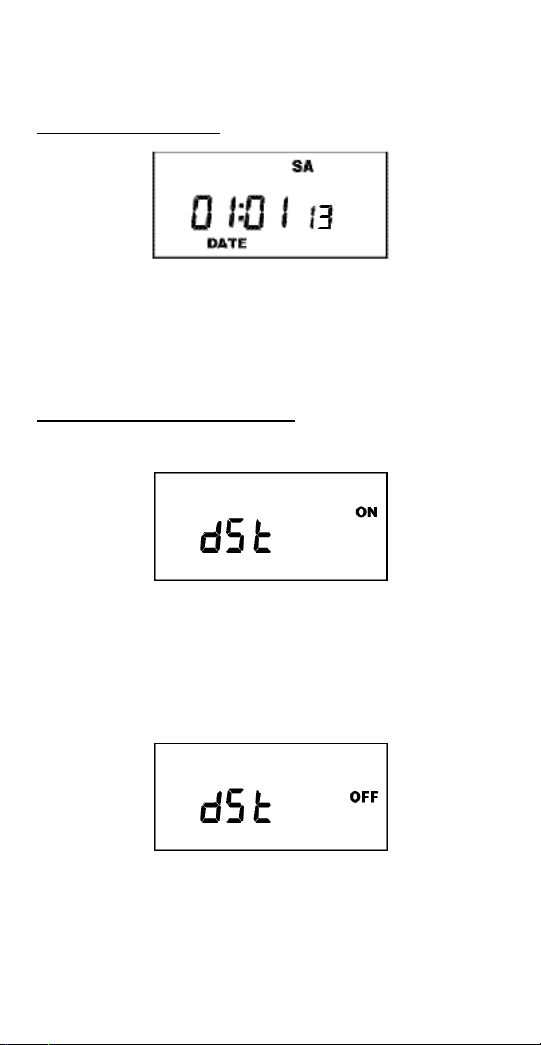
3.0 DATE SET MODE
Press MONTH, DATE, and YEAR key to advance to
the desired month, date and year, then press ENTER.
NOTE: The day of the week will automatically set
once the date is entered.
4.0 DAYLIGHT SAVING TIME
After setting or modifying the date, display will show:
a. For standard USA daylight savings (DSt), press
MODE and go to step 5.0.
b. For dates other than standard USA dates, press
MONTH and go to step 4.1.
c. If daylight saving time (DSt) is NOT required, press
DEL display will show:
Press ENTER then go to step 5.0.
3
Page 6
4.1 TO MODIFY STANDARD USA DAYLIGHT SAVINGS DATES
NOTE: The first two digits represent the month and
the second set of digits represent the week in the
month. Choices for week are 01 (1st), 02 (2nd), 03
(3rd) or L (Last) week of the month. The default day
is Sunday (SU.) Once modified date set, the unit will
automatically calculate the correct start dates in the
future.
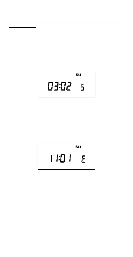
Now press MONTH and DATE buttons to modify the
starting DST settings. Pressing D AY changes default
day. EXAMPLE: A screen showing “04:01 SU S” repre sents April (04), the first week (01), Sunday (SU), and
the Start (S) of daylight savings time.
Press ENTER to save and the display will show:
Now press MONTH and DATE buttons to modify the
ending DST settings. Pressing DAY changes default
day. EXAMPLE: A screen showing “10: L SU E”
represents October (10), the Last week (L), Sunday
(SU), and the End (E) of daylight savings time.
Press ENTER to save and the display will show the
modified DSt starting date.
Press MODE twice to go to step 5.0.
4
Page 7
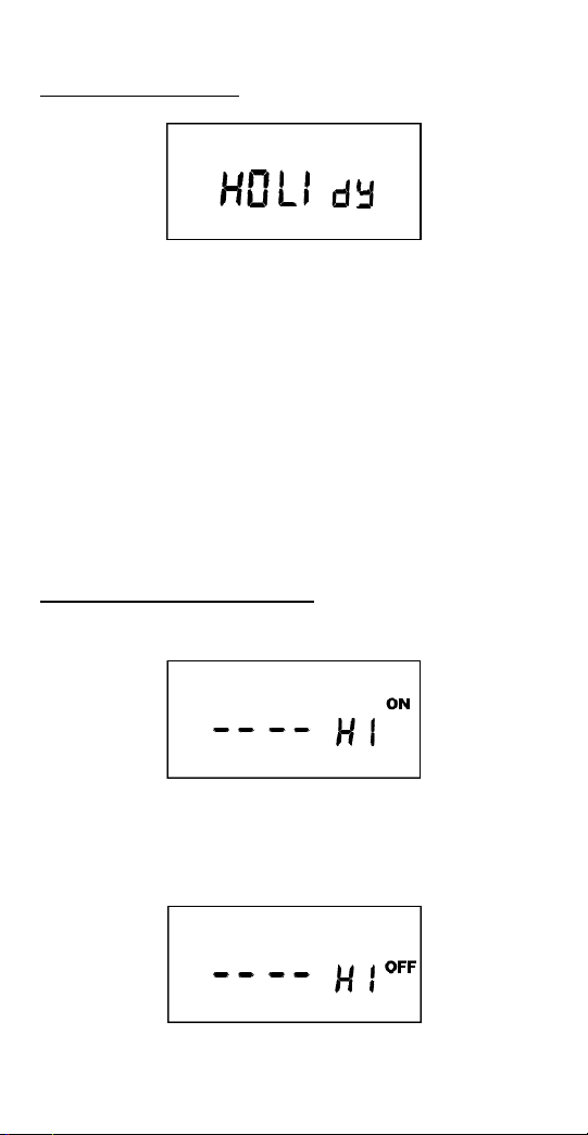
5.0 HOLIDAY DATES
You are able to select up to 9 holiday blocks, which
will exclude all of the regular schedules, and execute a
special set that will only run on those specified days. If
no holiday schedule is entered in step 6, operations
will be omitted during the block. Holiday blocks can be
anywhere from 1 day in length (the same start and end
dates) or up to 364 days. Holiday blocks cannot
end after they begin. If a holiday block must run from
December 18th through January 5th, you have to
program one block from 12/18 to 12/31, and then
another from 01/01 to 01/05.
To skip, press the MODE key.
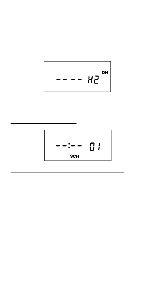
5.1 TO SET HOLIDAY DATES
Press the ENTER key.
Press the MONTH, and DATE keys to set the date to
the desired start date (H1 ON).
Press the ENTER key.
5
Page 8
For a single day holiday, press the ENTER key
(OR)
Press the MONTH, and DATE keys to set the date to
the desired end date (H1 OFF)
Press the ENTER key.
Repeat for all holidays.
Press MODE when holidays are complete.
6.0 SCHEDULE SET MODE
6.1 SETTING HOURS, MINUTES, AND DAYS
Note: A schedule is needed for each event. If a typical
ON/OFF pair is required, use SCH 01 for the ON
event and SCH 02 for the OFF event.
Press the HOUR, and MIN keys to set the desired time.
Press EVENT to set desired event (ON or OFF)
Press CH SELECT key to select channel on
two channel units.
Press DAY to set desired day(s).
Note: With each DAY button push a different group of
days will appear.
6
Page 9
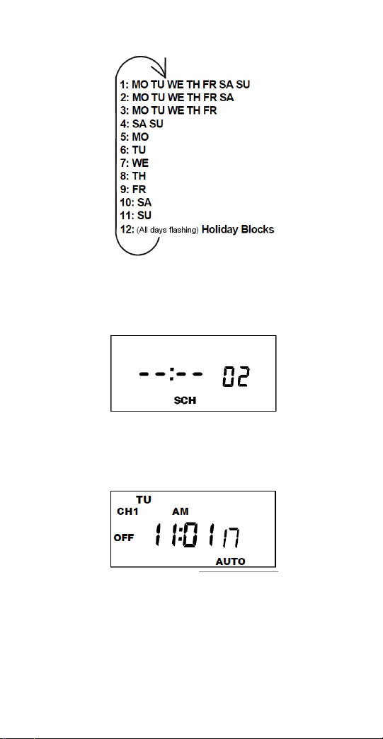
Note: Selection #12 will only show if a holiday date
has been entered in step 5.
Press ENTER to save.
Follow the same procedures above to set more
schedule entries.
Press MODE when schedules are complete.
Unit is in the AUTO (automatic) mode.
The word FLASH may appear to indicate a new
program has been written to memory.
7
Page 10

Press the EVENT key once (or twice for two channel
units) to activate current schedule then EVENT key
again to return to AUTO mode.
7.0 TO SET SUNSET ASTRONOMICAL SCHEDULE
Press MODE until display shows:
MO TU WE TH FR SA SU ASTRO
Press CH1/CH2 to select channel 1 or 2.
Press LAT key to advance to the desired degree of
latitude, from 0° to 60° north or 0° to 60° south.
Press ENTER. The display will show:
MO TU WE TH FR SA SU ASTRO
CH1 MOM AM PM OFFSET CH2
ON
OFF
7.1 SELECTING ASTRO DAYS
Press DAY to select desired days in which you want
the indicated channel to turn ON at sunset and then
press ENTER.
NOTE: Sunset Time will be based on Date and
Latitude entered. The display will show:
MO TU WE TH FR SA SU ASTR
CH1 MOM AM PM OFFSET CH2
ON
OFF
O
If an offset to sunset time is required, press HOUR
and MIN. Offset can be set to 3 hours and 59 minutes max. Press EVENT to select + or - and then
press ENTER.
8
Page 11

NOTE: A + sign will turn load ON that many hours
and/or minutes after sunset. A - sign will turn load
ON that many hours and/or minutes before sunset.
The display will show:
MO TU WE TH FR SA SU ASTR
CH1 MOM AM PM
ON
OFF
O
Press DAY and then ENTER to activate sunrise time.
NOTE: To turn load OFF at a preset OFF time, leave
this field blank. Press ENTER. The display will show:
MO TU WE TH FR SA SU ASTR
CH1 MOM AM PM OFFSET CH2
ON
OFF
O
If an offset to sunrise time is required, press HOUR
and MIN. Offset can be set to 3 hours and 59 minutes max. Press EVENT to select + or - and then
press ENTER.
NOTE: A + sign will turn load OFF that many hours
and/or minutes after sunrise. A - sign will turn load
OFF that many hours and/or minutes before sunrise.
Press MODE to return to the AUTO mode.
8.0 SUNSET ON AND USER-SELECTED TIME OFF
Set sunset ON per sections 7.0 and 7.1
USER-SELECTED TIME OFF:
Press MODE until SCH 01 appears. Press ENTER
until a blank schedule appears then press CH1/CH2
to select channel 1 or 2. Press HOUR, MIN and
EVENT to set desired OFF time. Press DAY to select
desired days and then press ENTER.
9
Page 12

8.1 USER-SELECTED TIME ON AND SUNSET OFF
Press MODE until SCH 01 appears. Press ENTER
until a blank schedule appears then press CH1/CH2
to select channel 1 or 2. Press HOUR, MIN and
EVENT to set desired ON time. Press DAY to select
desired days and then press ENTER.
SUNSET OFF:
Set sunset OFF per sections 7.0 and 7.1
8.2 TO DELETE SUNSET SETTINGS
a. To delete selected channel
Press MODE until the display shows:
MO TU WE TH FR SA SU ASTRO
CH1 MOM AM PM OFFSET CH2
Press CH1/CH2 to select desired channel and press
ENTER. Press DEL and then ENTER to delete all
unwanted entries.
b. To delete the sunset schedule for both channels
press MODE until the display shows:
MO TU WE TH FR SA SU ASTRO
CH1 MOM AM PM OFFSET CH2
Press DEL and ENTER. The display will show:
MO TU WE TH FR SA SU ASTRO
Press the MODE key to return to the AUTO mode.
10
Page 13

9.0 REVIEW, MODIFY AND DELETE
Press MODE to advance to any of the following
MODES:
1. AUTO MODE: In this automatic mode, the unit will
execute the scheduled programs. Time, day, seconds
and load status are displayed. If today is a
programmed holiday, the day of the week will flash.
OVERRIDE IN AUTO MODE: The load status of the
channel can be manually changed by pressing the
OVRD key (or OVR1 and OVR2 key for two channel
units).
The unit will stay in this position until the next
scheduled event. A flashing LCD load indication (ON,
OFF) shows the status was changed by the override
not a scheduled event.
Note: To force the circuit ON when an EPC-A photo
sensor installed, you must cover the photo sensor and
place the override into the ON position.
2. MAN MODE: In this manual mode, the unit will
ignore the schedule programs. Time, day, seconds
and load status are displayed. If today is a
programmed holiday, the day of the week will flash.
This can be used as a VACATION SETTING to keep
load off while away. Use override to set to OFF
position.
OVERRIDE IN MAN MODE: The load status of the
channel can be manually changed by pressing the
OVRD key (or OVR1 and OVR2 key for two channel
units).
The unit will stay in this position until OVRD is pressed
again. A flashing LCD load indication (ON, OFF)
shows the status was changed by the override not a
scheduled event.
11
Page 14

3. CLOCK MODE: Press HOUR and MIN to modify
existing settings. Press ENTER to save changes.
4. DATE MODE: Press MONTH, DATE and YEAR to
modify existing settings. Press ENTER to save
changes. DAY is automatically adjusted.
5. DSt MODE: Factory default is set at US standard
daylight savings dates noted by ON. To remove
daylight savings time setting, press DEL to
change screen to show OFF. DST may be activated
again by pressing DEL. Press ENTER to save
changes. To change from the standard DST month/
week/day setting press HOUR and refer to step 4.1.
6. HOLIDAY MODE: Press ENTER to advance to
desired holiday. Press MONTH and DATE to modify
start of holiday (ON) then press ENTER. Press
MONTH and DATE to modify end of holiday (OFF)
then press ENTER to save changes.
7. SCH MODE: To change schedule, press ENTER to
advance to desired event. Press HOUR, MIN, EVENT,
and DAY to modify time settings. Press DEL to delete.
Press ENTER after each modification to save changes.
NOTES:
1. Unit has a look back feature. Press the EVENT key
once (or twice for two circuit units) to activate current
schedule then EVENT key again to return to the
time (run) screen. Unit will automatically pick up the
last schedule.
2. To clear date and time only and provide unit with
a soft reboot, press and release the reset button that is
recessed under the small hole to right side of LCD
screen.
3. Clear all memory. To clear all memory, while in the
RUN mode, press ENTER, display will show:
12
Page 15

Use the EVENT key to display:
Now Press ENTER briefly and everything in the timer
memory is cleared and 12HOUR will flash.
4. A “PF” on the display indicates a Power Failure and
the unit requires AC power to operate. The time and
date are protected for 7 days by the super cap. The
program is retained in permanent memory.
5. A “Lo” on the display indicates that the super cap
has run low and the unit needs to be powered with AC.
A minimum of 8 hours is required to fully charge the
super cap.
Planning Your Program
The single channel unit will operate as a standard
timer for typical indoor or outdoor control needs. Only
if a photo sensor is connected can it operate with a
photo and time logic.
Two channel units allow you to set-up different control
logic for each channel by using the Select Switch. To
meet Title 24 requirements, one channel could be
sunset to sunrise while the other channel is sunset
to time OFF. Also one channel could be used for indoor
lighting control with fixed ON and OFF times while the
other channel is set for sunset to sunrise.
The photo sensor will only operate when the program is
set to ON. Here are examples for the most common
uses. For other ideas call the toll free Tork Tech Help
Line 888-500-4598.
1. Sunset ON and Sunrise OFF 7 days a week:
Program the channel for an ON event at 12:00am
Monday through Sunday. The photo sensor will take
full control and turn on the load ON only when light
level drops to the preset footcandles then turns OFF
13
Page 16

when the light level is twice the preset footcandles.
(For two channel units also set select switch to PHOTO
setting.)
2. Sunset ON and Time OFF: Program an ON event
at the earliest time you want to allow photo sensor to
begin to operate. Then program a night time OFF
event. (For two channel units also set select switch to
PHOTO setting.)
Example: ON at 3:00pm and OFF at 11:00pm MO –
SU. The photo sensor will take control at 3:00pm and
turn ON the load only when light level drops to the
preset footcandles, but timer will shut OFF the load at
11:00pm regardless of the light level at that time.
3. Time ON and Time OFF: Program the channel for an
ON event and an OFF event for the times you choose.
Do not connect a photo sensor. (For two channel units
photo sensor may be connected but also set select
switch to TIMER setting.)
Timed Override
Wiring a Tork SS410 to the remote override
connections provides an easy way to meet various
energy code requirements for indoor lighting. Include
the Tork #TRP to power the low voltage switch.
A Tork A502H may also be used to provide a low
cost 2 hour override.
INPUT CONNECTIONS
There are two removable terminal blocks on the rear of
the units. The terminal blocks, as viewed from the rear,
are labeled TB3 (left side, green), and TB2 (right side,
black).
TB3 is used to connect the EPC-A to the unit. Wire
the terminal block from left to right, with the blue, black,
and red wires going to the EPC-A, wire length not to
14
Page 17

exceed the length shown in the chart above. Calibrate
per instructions below.
The other terminal block, TB2 is used as remote
override inputs. Three wires are used: common
wire, channel 2 (if DGLC200A), and channel 1.
NOTE: Do not use any supply voltage for these wires.
They should only be connected to dry (unpowered)
switches. Closing contacts between the wires for
channel 1 and common together will turn load 1 ON.
Load will stay ON as long as the two wires are
connected, no matter what the timer is set for, or the
light level. Closing contacts between the wires for
channel 2 and common together will turn load 2 ON.
The load status change due to remote override will not
be shown in the display.
Photo Sensor Calibration
After installation, in order to ensure accurate light level
performance, completely cover the EPC-A sensor.
Then gently press the recessed Sensor CAL Switch
for at least 5 seconds. After this button has been
pressed, the red LED directly above the button will
blink four times. If the button is pressed accidentally
when the light level is above 10 foot candles, the unit
will not recalibrate and the LED will blink once to signal
that it did not change calibration.
15
Page 18

16
Page 19

The Light Level dial adjusts the foot-candle (fc) set
is for timer function only
point for the control to turn ON. The load will be turned
OFF and continue to hold OFF when the light level is
twice this level or more. A timer program must be active
for the light level feature to function see “Planning Your
Program” below.
The Time Delay dial adjusts the amount of time before
the load turns ON or OFF due to light level change.
The range is between 1 and 100 seconds. To prevent
short-duration events such as clouds or stray lighting
from prematurely turning the load ON or OFF, select
longer time durations.
Front Panel Controls
SENSOR CALIBRATION LED
SENSOR CALIBRATION SWITCH
connected, the control will follow a timer/light level logic.
Single channel front panel controls are used if photo sensor EPC-A
(Included with DGLC100A) is connected. When the photo sensor is
17
Page 20

SENSOR CALIBRATION LED
SENSOR CALIBRATION SWITCH
level logic. The down position (TIMER) is timer logic and ignores the photo sensor.
Each channel has a switch to set its independent control logic. The up position (PHOTO) is timer/light
Two channel front panel controls are use if photo sensor EPC-A (included with DGLC200A) is connected.
is for timer function only
18
Page 21

DGU100A/DGLC100A
DGUM100A
120/277VAC
DGU100A/DGLC100A
120/277VAC
DGU100A/DGLC100A
120/277VAC
DGU100A/DGLC100A
DGUM100A
120/277VAC
DGLC200A
120/277VAC
19
Page 22

2021222324
Page 23

Page 24

Page 25

Page 26

Page 27

Page 28

888.500.4598 • www.nsiindustries.com
 Loading...