

Page 1
CLOSED
OPEN
TX-Series
Quick Start Guide
Certifications and Specifications
For Options D, S, L, M, K, T, P, R, AS, & PB, calibration may be performed
using a Volt-Ohm meter by using the Ohm setting across COM and NO. When
switch is active, the meter will read <1.0 Ohms, or the Diode setting may be
used simply to indicate continuity. If a direct power source is being used, an
appropriately sized resistor must be used in series with the contacts, or
permanent damage will occur.
For all INDUCTIVE sensor options, a power source and resistors will be required
for calibration. (Refer to the product nameplate for current limitations.)
Setting Switches
GO™ Switch, Mechanical Switches, Reed Switches, AS-i, Profibus, & ALL
threaded, cylindrical inductive sensor options (except the D & S options).
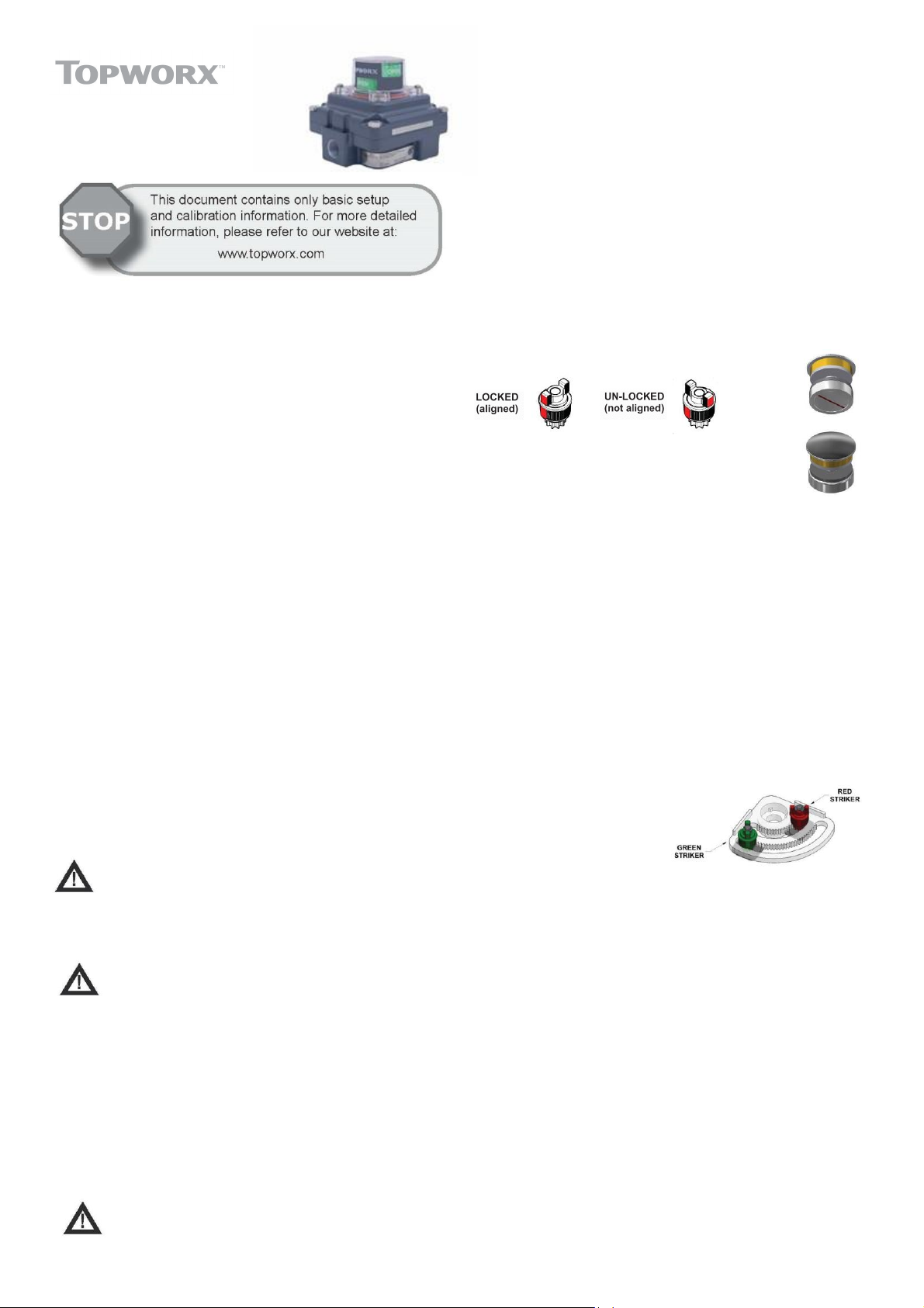
Each TX-Series unit is equipped with 2 or 4 adjustable targets with a usable
range between 45° and 90°. For normal acting applications, the targets are color
coded red for closed and green for open. The color code would be reversed for
reverse acting units. After installing the unit on the actuator or valve assembly,
the targets must be set.
Wiring Diagram
Installation Notes
TX-S eries products can be used on both linear and rotary valve automation
applications. Always use sound mechanical practices when mounting. When
fastening the TopWorx™ Switchbox to the bracket on the actuator, torque the
fasteners to 8 ft·lbs (10 .8 N·m) after cycling the valve a couple of times. This
allows the shaft to self-center in the pinion slot, or coupler. Be cautious not to
allow undue axial (thrust) load on the shaft.
This product comes shipped with conduit covers in an effort to
protect the internal components from debris during shipment and
handling. It is the responsibility of the receiving and/or installing
personnel to provide appropriate permanent sealing devices to
prevent the intrusion of debris, or moisture, when stored outdoors or
when installed.
It is the responsibility of the installer, or end user, to install t hi s
product in accordance with the National Electrical Code (NFPA 70),
or any other national or regional code defining proper practices.
Normal Acting Actuator:
Ste p 1: Rotate the valve full clockwise to the closed position.
Ste p 2: Unlock/push/twist the target as required to engage the switch and
lock target, if applicable.
Ste p 3: Rotate the valve full counterclockwise to the open position.
Ste p 4: Unlock/ push/twist the target as required to engage the switch and lock
target if, applicable.
Reverse Acting Actuator:
Ste p 1: Rotate the valve full clockwise to the open position.
Ste p 2: Unlock/push/twist the target as required to engage the switch and
lock target, if applicable.
Ste p 3: Rotate the valve or push and move the target a full counterclockwise to
the closed position.
Ste p 4: Unlock/push/twist the target as required to engage the switch and
lock target if, applicable.
For Switching Angle Under 45° (not applicable for D & S options):
When the switch box is mounted to a linear
actuator or when the actua tor strokes
less than 45°, we recommend the
following:
Ste p 1: Remove shaft from
Switchbox by removing
the circlip underneath the Switchbox .
Ste p 2: Remove the circlip underneath the cam, if equipped, then push the
cam down the shaft by 3-4mm and turn it 90°.
Ste p 3: Push the cam back up, you will see the flats fit snugly between the
locating lugs inside the hub.
Ste p 4: Replace the circlip.
Ste p 5: Remove the closed switch from the bracket and install it on the inside of
the bracket next to the open switch.
Factory Preset
All TopWorx™ products are factory set for 90° rotation on normal acting
actuators. The switch at full clockwise is for process valve closed and uses
the red striker. Whe n cha nging orientation, the target disk will must be
relocated for your application. The target is designed to be a djusted on 90°
increments allowing the TopWorx™ unit to be rotated 90°, 180°, or 270° from
standard. On reverse acting units, the switch function will be transposed.
Clockwise for open will become clockwise for closed. On units with indica tor
domes, the dome cov er with mask must be rotated to give proper indication.
Switch Calibration Procedure
Never perform the switch calibration procedure while in an area
that could be hazardous. On Intrinsically Safe models, the unit
must be wired in accordance with the control drawing included
with the product.
To Re-Assemble (not applicable for D & S options):
Ste p 1: Replace the sc rews with M3 X 25mm long screws (insert through both
switches and bracket and fasten with the nut on the inside closest to the
switch box bearing).
Ste p 2: Remove the Closed striker assembly (red) by removing the circlip or
screw on top and insta ll it on the inner rac k.
Ste p 3: Unlock target and twist the green striker to the other end of the cam’s
rack and lock target. (The red striker assembly should be twisted to
the other end of the inner rack).
Ste p 4: Re-install the shaft in the switch box and fit the s/s washer and circlip to
the underside of the switchbox.
Ste p 5: The switches can now be set anywhere between 0°& 45°.
Continued:
Page 2
For Switching Angle Up to 180° (D, S – 4 option can rotate up to
Spool Valve Specifications
Medium
Dried, filtered air (40 micron)
Operating Pressure
30psi (2.76Bar) - 100psi (6.89Bar)
Flow Coefficient
1.0Cv
Environmental Rating
Type 4, 4X, IP67 (metal enclosures only)
Port Size
1/4” NPT or BSP for 1.0Cv valve, exhaust ports are 1/8”
NPT or BSP
Ambient Temp Range
Refer to product nameplate markin g
Valve Body
Available in Hardcoat Anodized Aluminum or 316
Stainless Steel
Valve Seals
Silicone /EPDM
180° if only two targets are utilized):
Ste p 1: Remove shaft from Switchbox by removing the circlip underneath
the Switchbox.
Ste p 2: Remove the open switch from the bracket and install it on the inside
of the bracket.
Ste p 3: Remove the open striker assembly (green) by removing the circlip
or screw on top and install it on the inner rack next to the red
striker assembly.
Ste p 4: Re-install the shaft in the Switchbox and fit the s/s washer and
circlip to the underside of the Switchbox.
Ste p 5: The open switch can now be set anywhere between 90° & 180°.
Setting Slotted Inductive Sensors:
Ste p 1: Loosen set screw
Ste p 2: Rotate cam(s) and collar(s) until desired switch
function is achieved
Ste p 3: Tighten set screw
and the external ground connection, if supplied in addition, is supplemental
bonding allowed where loca l authorities permit, or is required. Refer to the TXSeries Master IOM for Proof Testing instructions. Switchbox cover sc rews are
not of standard form and they may only be replaced with identical screws
sourced from the manufacturer (minimum grade A2-70 or A4-80 to ISO 350 61).
Switchbox cover screws should be tightened to a minimum of 10.85 Nm (8 ft -lb).
When installing with a third party listed nipple-mount solenoid, it is the
responsibility of the installer to provide fittings, and apparatus, suitable for the
area classification in accordance with the National Electrical Code. All cable
entry devices or conduit stopping boxes shall be certified in type of explosion
protection, suitable for the conditions of use, and correctly installed.
The IIC enclosures are excluded from use in Carbon disulphide atmospheres.
The air pressure to the valve block, when fitted, shall not exceed 7 bar.
Preventative Maintenance
TopWorx™ Switchboxes are designed to operate for one million cycles without
servicing. Call TopWorx™ when you a re approaching this milestone for a
preventative maintenance kit and instructions.
Pneumatic Hookup Procedures:
Prior to connecting the supply air to the spool valve,
flush the system to remove any debris or contaminates.
Galvanized pipe can easily flake and contaminate the
system and therefore is not recommended. A 40 micron
point of use filter at every device is recommended.
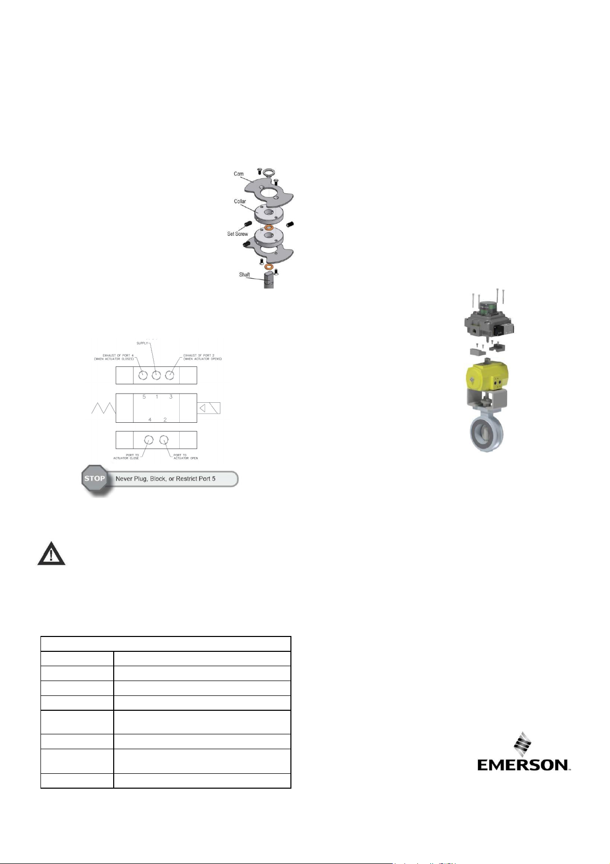
4-Way Spool Valves
The TopWorx™ spool valve is a 5-port, 4-way valve driven by an internally
mounted pilot valve. The spool valve supply port and work ports are marked as
follows:
Highly Recommended
TopWorx™ highly recommends Locktite 567 brand thread sealant. Do not use a
hard setting pipe compound. If Teflon thread seal tape is used, start the wrap
on the second thread from the leading thread of the fitting. This will
prevent tape shreds from contaminating the spool valve seals.
Breathers (AL-M30 1/8” NPT) should be installed in the exhaust
ports to k eep debris from falling into the spool valve and damaging the seals.
This must be addres sed prior to installation, or storage.
A flow control may be used in Port 3 but should NEV ER BE USED in Port 5.
Any blockage or restriction may cause an internal pressure build-up inside
the enc losure and pose a safety issue.
EC Declaration of Conformity
The products described herein conform to the provisions of the following
European Community Directives, including the lates t amendments:
Low Volta ge Directive (2014/35/EU)
EMC Directive (2014/30/EU)
ATEX Directive (2014/34/EU)
Typical Mounting Assembly
About Emerson-TopWorx
Emerson Process Management is the global leader in valve control and position
sensing for the process industries. Our solutions ena ble plants, platforms, and
pipelines to manage and control operations more intelligently and efficiently
under the most demanding and extreme conditions.
TopWorx™ discrete valve controllers enable automated on/off valves to
communicate via FOUNDATION Fieldbus, Profibus, DeviceNet, AS-Interface, and
HART protocols. They attach to all rotary and linear valves and actuators, and
carry a variety of global certifications.
GO™ Switch proximity sensors and limit switche s provide the ultimate position
sensing reliability and durability in extremely hot, wet, cold, dirty, abusive,
corrosive, and explosive environments.
For more information please visit www.topworx.com
Special Conditions of Safe Use (All Installations)
Clean only with a damp cloth to prevent possibility of electrostatic discharge.
For Explosion Proof installations, the internal ground connection shall be used
Global Locations
Americas
3300 Fern Valley Road
Louisville, Kentucky
40213 USA
+1 502 969 8000
Europe, Middle East, Africa
Horsfield Way
Bredbury Industrial Estate
Stockport SK6 2SU
United Kingdom
+44 0 161 406 5155
Asia-Pacific
1 Pandan Crescent
Singapore 128461
+65 6891 7550
The Emerson logo is a trademark and service mark of Emerson Electric Co. ©2020 Emerson
Electric Co . ©2020 TopWorx. All rights reserved. TopWorx, GO Switch, and VIP are all trademarks
of TopWorx. All other marks used in this document are the property of their respective owners.
Information contained herein is subject to change without notice.
ES-01420-1 R16
 Loading...