

Page 1

GTalarm2
Installation & Programming Manual
Security, monitoring and automation system
This manual includes steps to set up and use your system.
Page 2

The module GTalarm2 is a security, automation and access control
system with 6 zone inputs that is expandable to 32 zones, 6 analog inputs
0-10 V, 2 analog inputs 0-20 mA, 4 outputs 24 V /1000 mA open drain. 3
digital input/outputs The module GTalarm2 features up to 800 users, 32
sensors can be supported in any combination.
The module GTalarm2 provides the high level of protection residential
homes and any place where high security and automation is essential.
These systems are designed to be easy to use, and the modular concept
of these systems provides installers with labor-saving features that make
expanding, installing and servicing these systems quick and convenient.
Expand the module GTalarm2 by adding expansion module anywhere
and in any combination on the 1-wire bus. The Module is connected to the
bus at the most convenient location and then their zone inputs are
assigned to the desired zone and partition. Also, only a module’s used
inputs are assigned to zones in the system.
Once installed, all bus modules, including motion detectors, can be
programmed remotely via GPRS connection or via USB using SERA2
upload/download software.
The zones can be used to automate PGM activations.
The module GTalarm2 is a logical solution to every installer’s security,
access control and home automation installation needs.
Features of the module GTalarm2
Communication via SIA IP DC09 protocol
4 Analog inputs (pull up 5.1K) 0-10V
2 Analog Input/ Output , 0-10V , 0-20mA
3 Digital Inputs/Outputs 3.3V , 20mA,
Wiegand interface, Dallas 1-Wire Bus
4 PGM outputs 24V/1000mA. Open Drain.
Up to 32 sensors, temperature, humidity etc.
Digital expansion module BUS.
Built-in access control features
In-field firmware upgradeable via USB and SERA2 software
Events log buffer. 2048 events
Program remote controls using the master or installer codes
Up to 800 users remote controls with mob phone,
Up to 800 users remote controls with iButton or RFID keycard
Up to 800 user code. To control with Wiegand keyboard.
Built-in-real-time clock backup battery
Unlimited control via SMS.
External microphone / speaker
Push button software reset
Automation part
Security system’s part
Very important
Important
About the manual
The meaning of icons in the manual:
Page 3

Contents
1. General information about the module GTalarm2 ..................................................................................................................................................... 4
1.1. Specifications .................................................................................................................................................................................................... 4
1.2. Used definitions and terms ............................................................................................................................................................................... 4
1.3. Package content ............................................................................................................................................................................................... 5
1.4. General view of the module ............................................................................................................................................................................. 6
1.5. Meaning of LEDs and contacts ........................................................................................................................................................................ 7
1.6. Inputs ................................................................................................................................................................................................................ 8
1.7. Outputs.............................................................................................................................................................................................................. 8
2. First steps to prepare GTalarm2 and SERA2 software. ............................................................................................................................................ 8
3. Installation ................................................................................................................................................................................................................... 8
3.1. Power supply, Battery Wiring ........................................................................................................................................................................... 8
3.2. Humidity sensors AM2302/DHT22/AM2305/AM2306/AM2320/AM2321 ....................................................................................................... 9
3.3. Analog inputs 0-10V, 0-20mA, 4-20mA ......................................................................................................................................................... 10
3.4. Temperature sensors Dallas 1-wire DS18b20 installation & recommendations .......................................................................................... 11
3.5. Burglar Alarm sensor zones wiring EOL NO NC ........................................................................................................................................... 12
3.6. Guidelines for Locating Smoke Detectors and CO Detectors ...................................................................................................................... 14
3.6.1. [4-Wire] Smoke detector Wiring ................................................................................................................................................................ 14
3.6.2. [2-Wire] Smoke Detector Wiring to I/O Inputs .......................................................................................................................................... 15
3.7. Outputs. Bell & PGM Wiring ........................................................................................................................................................................... 16
3.8. Access control. Arming/ disarming methods ................................................................................................................................................. 17
3.8.1. Wiegand Keypad & RFID Card Reader Wiring ........................................................................................................................................ 18
3.8.2. iButton keys ............................................................................................................................................................................................... 19
4. Programming ............................................................................................................................................................................................................ 21
4.1. SERA2 Uploading/Downloading Software..................................................................................................................................................... 21
4.2. Security Programming Worksheets ............................................................................................................................................................... 22
4.3. General system options programming ........................................................................................................................................................... 23
4.4. System Fault/ Troubles Programming ........................................................................................................................................................... 24
4.5. Digital Inputs/ Outputs programming ............................................................................................................................................................. 26
4.6. Zones programming ....................................................................................................................................................................................... 27
4.7. 2-wire smoke detectors programming ........................................................................................................................................................... 29
4.8. Outputs. Bell & PGM programming ............................................................................................................................................................... 30
4.9. Users & Remote Control programming details. ............................................................................................................................................. 31
4.10. Wiegand Keypad & RFID card reader programming .................................................................................................................................... 32
4.11. iButton keys & RFID programming ................................................................................................................................................................ 33
4.12. DISARM /ARM/SLEEP/STAY the security system ....................................................................................................................................... 33
4.1. Reporting SMS&Dial in Case of Alarm Events .............................................................................................................................................. 34
4.1.1. Reporting to the user‘s mobile phone ....................................................................................................................................................... 35
4.1.2. Custom SMS Text ..................................................................................................................................................................................... 36
4.2. Reporting to the Central Monitoring Station .................................................................................................................................................. 36
4.2.1. GPRS/ IP/ TCP/ UDP details programming ............................................................................................................................................. 36
4.2.2. Central Monitoring Station details programming ...................................................................................................................................... 37
4.3. Event Summary (Events) ............................................................................................................................................................................... 38
4.1. RT Testing & Monitoring. Hardware. ............................................................................................................................................................. 39
4.2. RT Testing & Monitoring Security Alarm Panel/ Access ............................................................................................................................... 40
4.3. Automation & Sensors Programming ............................................................................................................................................................ 41
4.4. Sensors Configuration .................................................................................................................................................................................... 42
4.4.1. Humidity sensors AM2302/DHT22/AM2305/AM2306/AM2320/AM2321 Configuration ......................................................................... 42
4.4.2. Analog inputs 0-10V, 0-20mA, 4-20mA Configuration ............................................................................................................................. 43
4.4.3. Temperature sensors Dallas 1-wire DS18b20 Configuration .................................................................................................................. 43
4.1. Automation/Sensors (Automation/Sensors/Analog Inputs) Programming in SERA2 Software ................................................................... 43
4.2. Data Transmiting to Server & Remote Control .............................................................................................................................................. 46
4.2.1. TCP/ IP Remote Control ........................................................................................................................................................................... 46
4.3. Events Log ...................................................................................................................................................................................................... 47
4.4. Remote Monitoring, Control, Configuration, FW update over the internet ................................................................................................... 48
4.5. Testing & Monitoring Automation ................................................................................................................................................................... 50
4.5.1. RT Testing & Monitoring > Sensors/ Automation ..................................................................................................................................... 50
4.5.2. RT Testing & Monitoring > Event Monitoring ........................................................................................................................................... 51
5. Info: Hardware, Firmware, Bootloader, Serial No & Updates ................................................................................................................................. 51
6. Recommendations for the user & installer ............................................................................................................................................................... 52
7. Remote control and configuration using SMS Commands ..................................................................................................................................... 53
7.1.1. The table of installers commands ............................................................................................................................................................. 53
7.1.2. The table of users commands ................................................................................................................................................................... 55
8. Warranty Terms and Conditions .............................................................................................................................................................................. 56
Page 4
1. General information about the module GTalarm2
Parameters of built-in GSM module:
Quad-band (850/900/1800/1900 MHz)
Sending of SMS messages
Receiving of calls and dialing
Data download/upload via GPRS network
Outputs (PGM):
OUT1 max current – (-V) 1000 mA.
OUT2 max current – (-V) 1000 mA.
OUT3 max current – (-V) 1000 mA.
OUT4 max current – (-V) 1000 mA.
All outputs can be controlled via short call
DIAL or via SMS message. This feature may
be used for gate opening, ignition locking etc.
Output alarm parameters may be
programmed.
Programmable algorithms for outputs
operation: CTRL/SMS/DIAL, SIREN, BUZER,
ARM state, Zones OK, Light Flash, inverting,
pulse mode
IN1 - IN4 inputs:
SMS text for input alarm and restore
Available to control until 32 sensors
Programmable enabling or disabling of inputs;
Burglary alarm zones. Input type
NC/NO/EOL/EOL+TAMPER 2.2K + 2.2K
5.1K pull up resistor.
Analog input 0-10V
Algorithm for zones operation: delay, interior,
instant, 24 hours, silent, fire
Response time;
Time of additional response;
Commutation of selected output
Control of analog sensors
Inputs/outputs I/O1-I/O2:
Programmable input or output
Burglary alarm zones. Input type: NC/NO/EOL/
EOL+TAMPER
Analog 0-10V/0-20mA/4-20mA
Control of analog sensors
Digital inputs/ outputs D1-D3:
Programmable optional digital input or output
Max. Voltage 3.3V
Dallas 1-Wire Bus, DS18b20, DS1990A
Aosong 1-Wire bus Humidity Sensor
AM2302 DHT22 AM2305 AM2306 AM2320
AM2321
Wiegand interface DATA0/ DATA1, RFID
reader, Keyboard.
The total length of the bus from 10 to 100m.
Module control:
ARM/DISARM of the security system via:
„Key switch” input level or pulse mode.
SMS message 800 users
short call DIAL 800 users
Maxim-Dallas iButton key (iButton DS1990A –
64 Bit ID)) 800 users.
Wiegand keypad code or RFID keycard or key
fob 800 users
3.3V power source output for external
modules:
Voltage 3.3V
Current limit 100mA
BUS expansion modules or programmable
input/output:
Voltage 8-15V
Current 20mA
Automatic periodical test:
Test sending in a form of SMS message.
Periodicity for communication control
messages (tests) from 1 to 99 nights and
days according to selected time. Or fixed
periodical interval 1-99999 minutes.
Power supply voltage:
Nominal power supply voltage – 12.6 V
Power supply voltage range 8 – 15 V
Max. Allowed ripple voltage 100mV
Consumption current:
In standby mode less than 50 mA.
In dialing or SMS/GPRS sending mode
less than 300 mA.
Events Log:
Nonvolatile flash events log 2048 events
Environmental parameters:
Storage temperature range from -40 to
+85 oC / -40 to 185 oF
Operational temperature range from -30
to +75 oC / from -22 to 167 oF
Max relative humidity under +40 oC / 104
o
F 95%
Package weight 90g
Module weight: 43g
Overall dimensions of the module:
84x66x18mm
Term
Description
Alarm Log
Contains information about alarms that are currently active on the system or information about alarms that have been
raised and then resolved on the system. This log can be useful in analyzing problems and trends in the system.
Arming/Disarming
A process of enabling/disabling system's security.
Authorized user
It is a person whose mobile phone’s number is entered in GSM module. Two authorized users with the same rights may
be entered into the module.
Backup battery
The secondary power source of the system. In case of a main power failure, the backup battery will take over.
Bell squawk
If enabled, the siren/bell indicates the completed system arming and disarming process (except the arming in STAY mode).
After the system is successfully armed, the siren/bell will emit 2 short beeps and 1 long beep after the system is disarmed.
By default, the parameter is disabled.
Bypass/Activate Zone
Zone bypassing allows the user to deactivate a violated zone and arm the system without restoring the zone. If a bypassed
zone is violated or restored during exit/entry delay, or when then system is armed, it will be ignored. The zone will remain
bypassed until the system is disarmed. Zones can only be bypassed and activated when the system is not armed.
Caller ID
Caller's identification
COM
Negative power supply terminal.
Confirmation timeout
Specifies the time in which a cross zone must be violated that the system could confirm alarm on the associated zone.
Configuration
Programming of the settings, which will define the operation of the item. For example, user's telephone numbers, set-up of
periodicity for sending SMS message, input names etc.
CMS
Central monitoring station
DIAL
The system makes a call to the number specified.
Diagnostic Tool
When using Configuration tool software, you may use a section of functions, that allows to monitor real-time zones, view
changes of peripheral devices, instantly configure necessary options, for example, enabling/disabling PGM outputs, etc.
Entry Delay
Once the exit delay has expired, the system initiates the entry delay countdown if a Delay type zone is violated. The
countdown is indicated by short beeps emitted by keypad buzzer and by steady beep emitted by system's buzzer. The
indication is intended to advise the user that the system should be disarmed. If the system is disarmed before the entry
delay expires, no alarm will be caused.
EOL
(End of line resistor) input type with resistor.
Event
The information that the user receives.
1.1. Specifications
1.2. Used definitions and terms
Page 5
Event Log
A list of system events that is uploaded from the device‘s memory to the configuration software for further analysis. The
system logs all information about system configuration, system actions and info messages.
Exit Delay
A period of time intended for user to leave the secured area. The system begins the countdown after the arming process
initiation.
Fault
A specific problem or error that prevents the system from working properly. The system comes equipped with selfdiagnostic feature allowing to indicate the presence of any system fault by the keypad as well as by SMS text message
notification to the listed user phone number.
iButton key
A unique 64-bit ID code containing chip enclosed in a stainless steel tab usually implemented in a small plastic holder. The
module supports up to 800 iButton keys each holding a unique identity code (ID), which is used for system arming and
disarming.
Installer
a person provided with INST (installer's) password
Master/User Code
Allows to carry out system arming/ disarming as well as minor system configuration and control
MIC
microphone
Normally closed (NC)
It is a switch that passes current until actuated.
Normally open (NO)
It is a switch that must be actuated to pass current.
Periodic Test Event
Provides the following information on alarm system: date & time, status (armed/disarmed), GSM signal strength, mains
power supply status, temperature value measured by primary and secondary temperature sensors (if any).
Pull-up resistor
Is that it weakly "pulls" the voltage of the wire it is connected to towards +V (or whatever voltage represents a logic "high").
PGM output
A PGM output is a programmable output that toggles to its set up state when a specific event has occurred in the system,
the scheduled weekday and time has come or if the user has initiated the PGM output state change manually.
Ping period
Sets period of time defining how often the module sends ping data packet to the server.
Protocol
A formal specification for communicating; an IP address the special set of rules that end points in a telecommunication
connection use when they communicate. Protocols exist at several levels in a telecommunication connection.
Service messages
ARM/DISARM, test, resetting of the system.
SSR
Solid State Relay
SMS forward
System can re-sent all incoming SMS messages to the specified users. It is useful if the GSM operator of the inserted SIM
card sends some useful information (SIM card validation or payment account status and etc.) or it is necessary to monitor
all incoming SMS messages by specified user.
User
It is a person being aware USER password.
Zone
Detection devices such as motion detectors and door contacts are connected to the alarm system’s zone terminals.
Zone state/status
Zone status is a position of a certain zone being enabled or disabled. Meanwhile, zone state points out the condition of a
certain zone, which can either be violated (i.e. In case of alarm) or restored.
+V
Positive power supply terminal.
1.3. Package content
GTalarm2 module – 1 pcs
GSM antenna - 1 pcs
Shipping Package - 1 pcs
2.2 kOhm resistors - 12 pcs
5.1 kOhm resistors – 2 pcs
Spaces for PCB installation 4 pcs
Package content may be vary without a notice. Ask the seller before buying!
External microphone with 1
m cable and connector
iButton probe with LED indicator
GSM antenna with cable
Mini USB cable
Table 1 Standard package content
Table 2 Additional, under request package content
Page 6
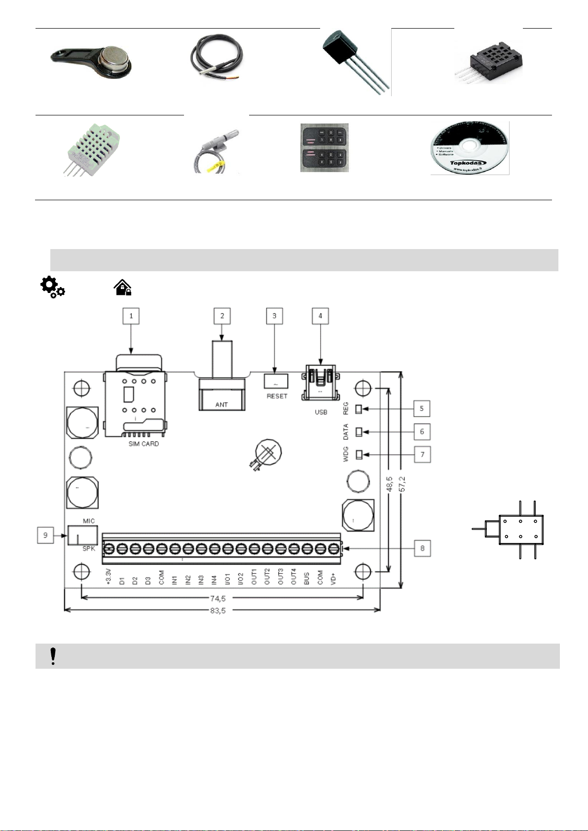
iButton DS1990A-F5+ key
Water Proof DS18b20 Temperature
Probe with 1m cable
Temperature sensor DS18B20
Humidity sensor AM2320
Humidity sensor DHT22
(AM2302)
Humidity sensor AM2305
Wiegand keypad & RFID reader
Mini CD - 1 pcs: User’s guide
in PDF Program SERA2
1. Micro SIM card holder of
“Push-Push” type
2. GSM antenna connector
3. RESET button
4. Mini USB programming
connector
5. REG (yellow) see table 3
6. DATA (red) see table 3
7. WDG (green) see table 3
8. Power supply and
input/output connector
9. External microphone
connector
Do not locate SIM card with force, because you may damage SIM card holder
SPK
MIC MIC
SPK
COM
Figure 1 GTalarm2 PCB Layout
1.4. General view of the module
Page 7
Name
Indication variations
Meaning
WDG (green) built-in
LED
Watchdog heart beat blinking, remains lit
for 50ms, and turns off after 1000ms.
The module is functioning.
Off
The module is out of order or no voltage
REG (yellow) built-in
LED
Lights continuously
Modem has been registered to the network
Flashes, remains lit for 50ms, turns off for
300ms
Modem is being registered to the GSM network.
Blinking fast, remains lit for 50ms turns off
for 50ms
PIN code of SIM card error. PIN code request should be removed or
correct PIN code should be entered.
Off
Modem failed to register to the network.
DATA (red) built-in LED
Lights continuously
The memory of the module contains unsent reports to the user or to the
server.
Off
All reports has been send.
Optional functions and Description
1
VD+
15
Positive supply contact
Power supply voltage
8-15V
Current in standby mode
<50mA
Current when sending data
<300mA
2
COM
Negative supply terminal for keyboard(s), indicators and sensors.
3
BUS
15
Programmable functions
Expansion module data BUS
Output, 20mA
Input
Max available voltage
15V
4 … 7
OUT1 ...
OUT4
24
Programmable Output PGM1 - PGM4. Drain type. When state is ON, connects internally to COM
Max available current
1000mA
Max available voltage
24V
8, 9
I/O1-I/O2
15
Programmable functions
The zone for security system NC/NO/EOL/EOL+Tamper
[1]
Output 20mA
Analog current input 0-20mA
Analog voltage input 0-10V
Max available voltage
15V
10 …
13
IN1 … IN4
15
Programmable functions
Input with 5.1K resistor to the VD+ (Pull UP)
The zone for security system NC/NO/EOL/EOL+Tamper
Analog input 0-10V
Max available voltage
15V
14
COM
Negative supply terminal for keyboard(s), indicators and sensors.
15 D3 3.3
Programmable functions
Digital output
Digital input
Dallas 1-Wire bus. DS18b20, DS1990A
Aosong 1-Wire bus. Humidity Sensor AM2302, DHT22, AM2305,
AM2306
Wiegand (1) interface DATA1 , RFID reader, keypad
Max available voltage
3.3V
Max available current
20mA
16 D2 3.3
Programmable functions
Digital output
Digital input
Dallas 1-Wire bus. DS18b20, DS1990A
Aosong 1-Wire bus. Humidity Sensor AM2302, DHT22, AM2305,
AM2306
Wiegand (1) interface DATA0 , RFID reader, keypad
Max available voltage
3.3V
Max available current
20mA
17
D1
3.3
Programmable functions
Digital output
Digital input
Dallas 1-Wire bus. DS18b20, DS1990A
Aosong 1-Wire bus. Humidity Sensor AM2302, DHT22, AM2305,
AM2306
Max available voltage
3.3V
Max available current
20mA
18
3.3V
3.3
Power supply for external temperature, humidity sensors
Max available voltage
3.3V
1.5. Meaning of LEDs and contacts
Table 3 Meaning of LEDs
Table 4 Terminal block. Contacts.
Page 8
Max available current
100mA
[1] If the zone used for security system purpose 5.1k pull-up resistor should be connected
Preparation procedure of the module GTalarm2.
Connect the GSM antenna to the antenna connector.
Insert the SIM card in the SIM card holder. Ensure that PIN request function is disabled.
Connect the module to the computer via mini USB cable.
Install configuration software SERA2.
Go to the http://topkodas.lt/ website and download SERA2 software.
Open the folder containing installation of the software SERA2. Click the file „SERA2 setup.exe“
If installation directory of the software is OK, press [Next]. If you would like to install the software in the other directory press [Change],
specify other installation directory and then press “next”.
Check if the correct data are entered and press Install
After successful installation of the software SERA2, press [Finish]
You can find wiring diagrams in the Error! Reference source not found.. You can find detailed information about security system’s
configuration in the Error! Reference source not found.
1.6. Inputs
The module GTalarm2 has:
4 analog inputs (In1...In4 (0-10V)) for analog sensors connection. Or can be used or use it as security system‘s zones with selectable type:
NC/NO/EOL/EOL+TAMPER.
2 programmable analog inputs (I/O1, I/O2(0-10V/0-20mA)) for analog sensors control or using as security system‘s zone with selectable
type: NC/NO/EOL/EOL+TAMPER
3 programmable digital inputs (D1...D3(Max voltage 3.3V)) used for:
Wiegand interface DATA0/ DATA1, FID reader, Keyboard.
o Dallas 1-Wire Bus. To connect temperature sensors DS18b20 or iButton key DS1990A,
o Aosong 1-Wire bus Humidity Sensor AM2302, DHT22, AM2305, AM2306,
1.7. Outputs
The module GTalarm2 has:
4 open drain (1A) outputs: OUT1 (1A)… OUT4 (1A). The outputs can be used for siren, relay, lamp connection. These outputs can be
controled via short call or sms. Output operation algorithms: Automation /CTRL, Siren, Buzzer, ARM state, Zones OK, Light Flash, inverting,
pulse mode
2 open drain (20mA) outputs: I/O1 (20mA)… I/O2 (20mA). These outputs can be used for solid state relays, LED, to control devices up to
20mA.
3 outputs: D1 (10mA, Max Voltage 3,3V) for LED, solid state relays control.
1 programmable output BUS. Voltage 8-15V, Current 20mA
OUT1… OUT4 max current – (-V) 1000 mA.
All outputs can be controlled via short call DIAL or via SMS message. This feature may be used for gate opening, ignition locking etc.
Output alarm parameters may be programmed.
Programmable algorithms for outputs operation: CTRL/SMS/DIAL, SIREN, BUZER, ARM state, Zones OK, Light Flash, inverting, pulse
mode
Max voltage 3,3V
2. First steps to prepare GTalarm2 and SERA2 software.
3. Installation
This Installation & Programming manual provides the basic installation, wiring and programming information required to program the module
GTalarm2 and connect all third party devices to the module.
3.1. Power supply, Battery Wiring
Page 9
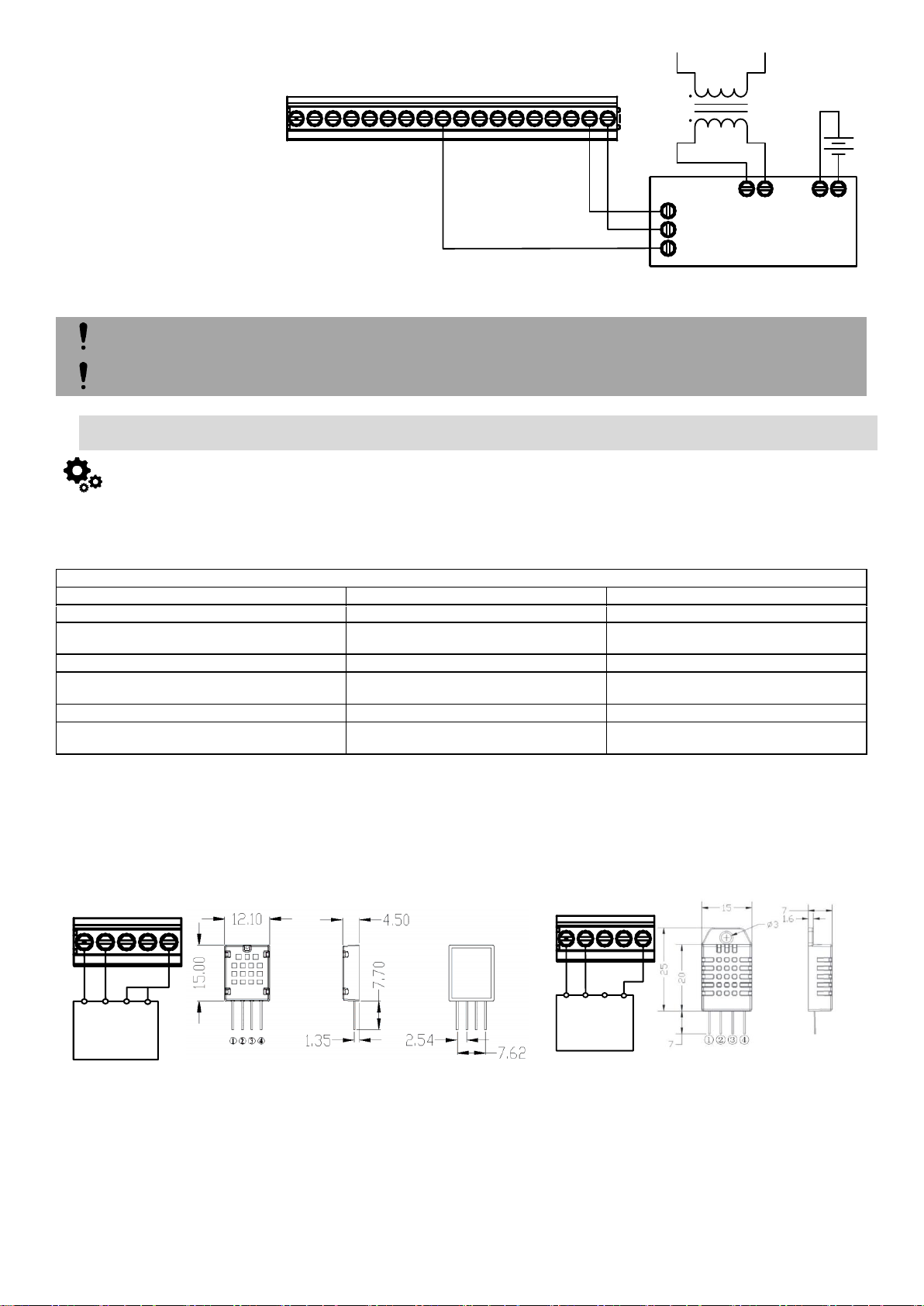
It is possible to supply the security
system from stabilized power supply
source 10-15 V and not less than
1,5A. It is necessary to calculate max
current of power supply. The current
of the alarm system is the current
used by sensors, relays, siren and
other devices. It is most convenient to
use power supply source applied for
power supply of security systems with
the option to connect backup lead
battery. It is recommended to mount
remote control relays into sockets.
Sockets may be easily fixed in metal
box. It is necessary to select relays
according to preferred voltage and
current.
Figure 2 Power supply connection
AC equipment cannot be connected directly to the module. It is necessary to use a special relays or other methods, which are in
compliance with electrical safety requirements.
When controlling devices from the AC network, it is necessary to follow all electrical safety requirements.
Manufacturers' Specification
AM2302
AM2320/AM2321
Operating Range
0–100
0–100
Absolute accuracy
(%RH, 25°C)
±3% (10-90%)
±5% (<10, >90%)
±3% (10-90%)
±5% (<10, >90%)
Repeatability (%)
±0.3
±0.1
Long term stability
(% per year)
0.5
0.5
1/e Response (sec) 5 5
Voltage supply (V)
3.3–5.5
3.1–5.5(AM2320)
2.6–5.5(AM2321)
Figure 17 AM2320 connecting diagram
Figure 18 AM2302 connecting diagram
1. Connect AM2320 or AM2302 to D1, D2, D3 according connection diagram.
2. Sensor’s type should be select in the System Options> Digital I/O Settings window. Set digital input definition D1, D2, D3 to Aosong 1 Wire
bus Humidity Sensor AM2302
3. Write configuration
4. Power module.
5. After module starts, wait a minute while sensor will be found on the bus.
6. Read configuration
7. Go to “Automation/ Sensors” window in the SERA2 software
8. Double click on the selected sensor’s line.
COM
+12V
AC Fail
AC 18V
AC 18V
BAT+
BAT-
External power supply
Transformer
~18-24V
Backup Battery
12V
OUT1
COM
BUS
OUT4
I/O1
IN4
IN3
IN2
D3
OUT2
+3.3V
OUT3
D1
D2
VD+
COM
IN1
I/O2
GTalarm2
+3.3V
D3
D1
D2
COM
AM2320
VCC
SCL
SDA
GND
D1, D2, D3
1
2
3
4
+3.3VD3D1
D2
COM
AM2302
VDD
SD1
NC
GND
D1, D2, D3
1
2
3
4
3.2. Humidity sensors AM2302/DHT22/AM2305/AM2306/AM2320/AM2321
Module should work with following sensors: Aosong 1-Wire bus Humidity Sensor AM2302, DHT22, AM2305, AM2306. Also a new smaller sensor
exists AM2320 & AM2321.
Table 5 Sensors AM2302, AM2320/AM2321 specification
The table lists values taken from datasheets. The Aosong data sheets do not specify maximum tolerances for most parameters, just 'typical'
values. It would therefore seem that any particular device is not guaranteed to meet these specifications. For all the other devices the numbers above
are the maximum tolerances and most also offer better 'typical' specifications.
Each AM2302 sensor connects on separate bus line to digital inputs (D1, D2, and D3). Total up to 3 AM2302 Aosong (Guangzhou) humidity
sensors can be connected to GTalarm2
Steps to start AM2320 and AM2302 sensors:
Page 10
9. Click on “Sensor type/ hardware location” and default sensor settings appear.
10. In sensors table column Sensor HW ID find registered sensors AM2302 looks like "GTalarm, Input D1, 1-Wire, AM2302 Huminidty" Location
of the sensor can be changed choosing wanted sensor in the list
11. Double click on the sensor row opens selected sensor window
12. Set other parameters of the sensor MIN, MAX values Units etc.
13. Write configuration to module
14. Open RT Testing&Monitooring Window > Hardware. Press [Start monitoring] button
15. Go to RT Testing&Monitooring Window > Event Monitoring TAB. Software will show real time sensor values, and alarm states
16. If you need to receive sms with sensors alarm, go to GSM Communication > SMS DIAL Reporting window. Enter telephone numbers of
users and mark alarm events that you want to receive. Open "Reporting SMS&DIAL" window. Set user phone number, and choose reporting
option Sensor1 - Sensor32 Alarm/Restore. Module will send SMS to user then sensor alarm event occurs
17. Write configuration
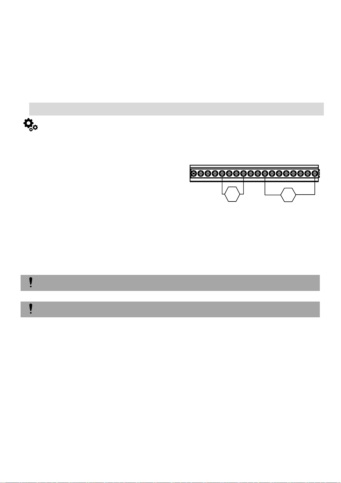
Any automation voltage analog sensors 0-10V, can be connected to IN1-IN4 (has internal pull up resistor 5.1K) , and I/O1, I/O2
Current measure analogue sensors can be connected to I/O1 and I/O2 0-20mA, 4-20mA
OUT1
COM
BUS
OUT4
I/O1
IN4
IN3
IN2
D3
OUT2
+3.3V
OUT3
D1
D2
VD+
COM
IN1
I/O2
V
A
4-20mA0-10V
Figure 3 Analog sensor connection
3.3. Analog inputs 0-10V, 0-20mA, 4-20mA
Steps to start analog sensors:
1. Connect analog voltage sensors to IN1, IN2, IN3, IN4, and current
I/O1, I/O2 according connection diagram.
2. The analog inputs can be used as security system zones or
analog sensors.
3. If analog inputs sensors is not in use, the inputs should be
disabled in “Zones” or “Sensor” window.
4. Analog sensors should be calibrated in the Automation/Sensors
window. Double click on the selected sensor’s line. Analog
sensors could be selected from the default list. Units could be
changed. Sensors calibration is possible by changing multiplier,
offset.
5. When all changes has been done, the configuration should be
written to module, by pressing write icon.
6. Open RT Testing&Monitooring Window > Hardware. Press [Start
monitoring] button
7. Go to RT Testing&Monitooring Window > Event Monitoring TAB. Software will show real time sensor values, and alarm states
8. If you need to receive sms with sensors alarm, go to GSM communications > SMS Dial Reporting window. Enter telephone numbers of
users and mark alarm events that you want to receive. Open "Reporting SMS&DIAL" window. Set user phone number, and choose reporting
option Alarm/Restore. Module will send SMS to user then sensor alarm event occurs
9. Write configuration
Page 11
3.4. Temperature sensors Dallas 1-wire DS18b20 installation & recommendations
The DS18B20 digital thermometer provides
12-bit Celsius temperature measurements.
The DS18B20 communicates over a 1-Wire
Each DS18B20 has a unique 64-bit serial
code, which allows multiple DS18B20s to
function on the same 1-Wire bus. Thus, it is
simple to use one to control many
DS18B20s distributed over a large area.
Applications that can benefit from this
feature include HVAC environmental
controls, temperature monitoring systems
inside buildings, equipment, or machinery,
and process monitoring and control
systems.
Applications/Uses
Consumer Products
Industrial Systems
Thermally Sensitive Systems
Thermometers
Thermostatic Controls
Key Features
Measures Temperatures from -55°C to +125°C (-67°F to +257°F)
±0.5°C Accuracy from -10°C to +85°C
Each Device Has a Unique 64-Bit
D3
+3.3V
D1
D2
COM
data
com
+3.3V
1 2 3
470µF ...4700µF
1 wire D1...D3
Temperature sensor
DS18b20
OUT1
COM
BUS
OUT4
I/O1
IN4
IN3
IN2
D3
OUT2
+3.3V
OUT3
D1
D2
VD+
COM
IN1
I/O2
100-120 Ohm
max 100m line
Sensor1 DS18b20
Sensor2 DS18b20
Sensor3 DS18b20
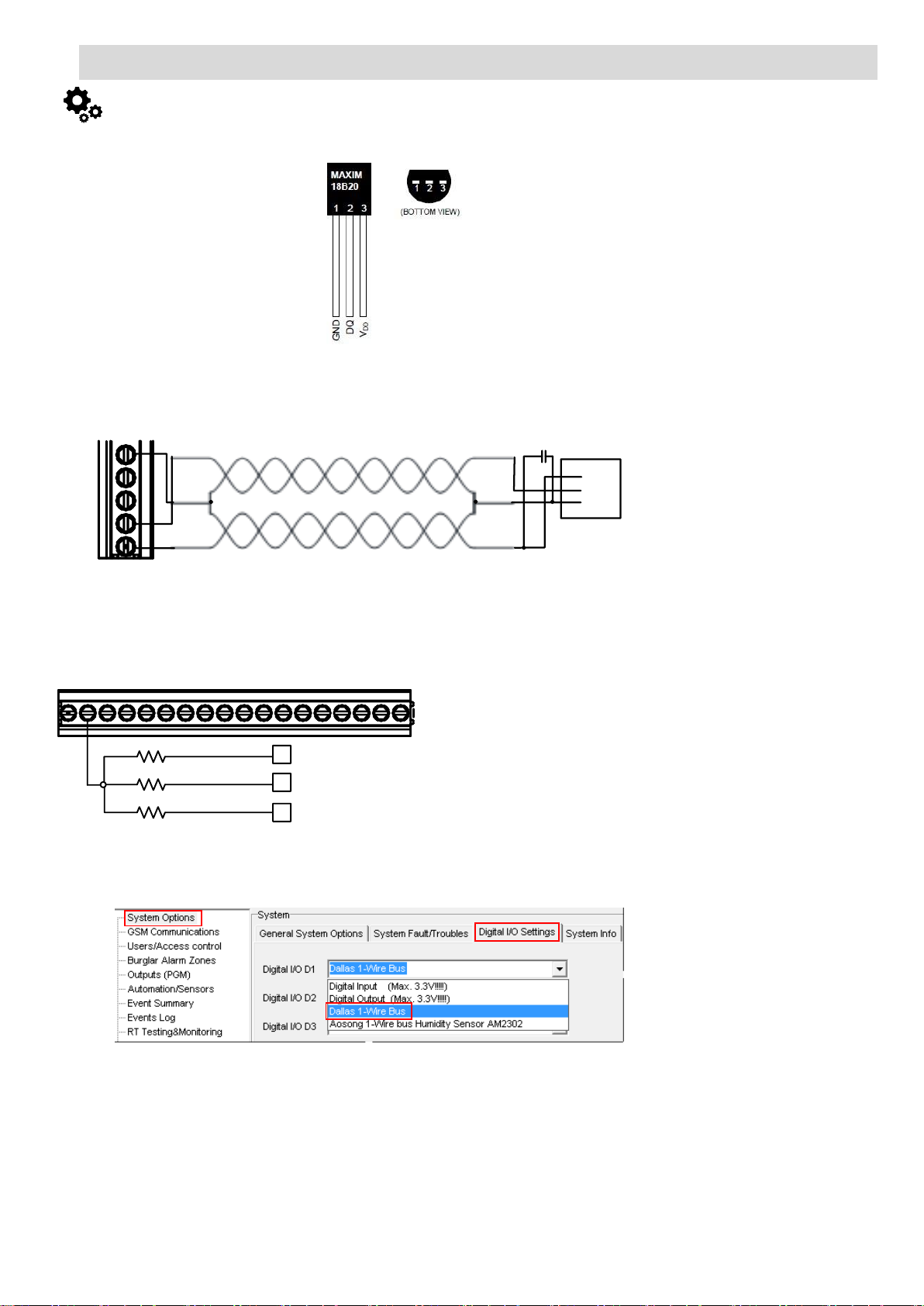
Figure 4 Star connection
Figure 6 How to find System Options> Digital I/O Settings window
Steps to start DS18b20 sensors:
1. Connect 1-Wire sensors DS18b20 to D1, D2, D3 according connection diagram.
Figure 5 iButton readers connection with long distance UTP or FTP cable
2. If you need to connect more sensors to the same input, connect them as a star or serial
3. Sensor’s type should be select in the System Options> Digital I/O Settings window. Set digital input definition D1, D2, D3 to Dallas 1-Wire
Bus option.
4. Write configuration
5. Power module.
6. After module starts , read configuration
7. Go to “Automation/ Sensors” window in the SERA2 software
8. Double click on the selected sensor’s line.
9. Click on “Sensor type/ hardware location” and default sensor settings appear. In sensors table column Sensor HW ID find registered sensors
DS18b20 looks like "GTalarm, Input D1, 1-Wire, DS18B20 Temperature, SN:28AE51560500" Location of the sensor can be changed
choosing wanted sensor in the list.
10. Double click on the sensor row opens selected sensor window. Set other parameters of the sensor MIN, MAX values Units etc.
11. Write configuration to module
12. Open RT Testing&Monitooring Window > Hardware. Press [Start monitoring] button
13. Go to RT Testing&Monitooring Window > Event Monitoring TAB. Software will show real time sensor values, and alarm states
Page 12
14. If you need to receive sms with sensors alarm, go to GSM Communications > SMS DIAL Reporting window. Enter telephone numbers of
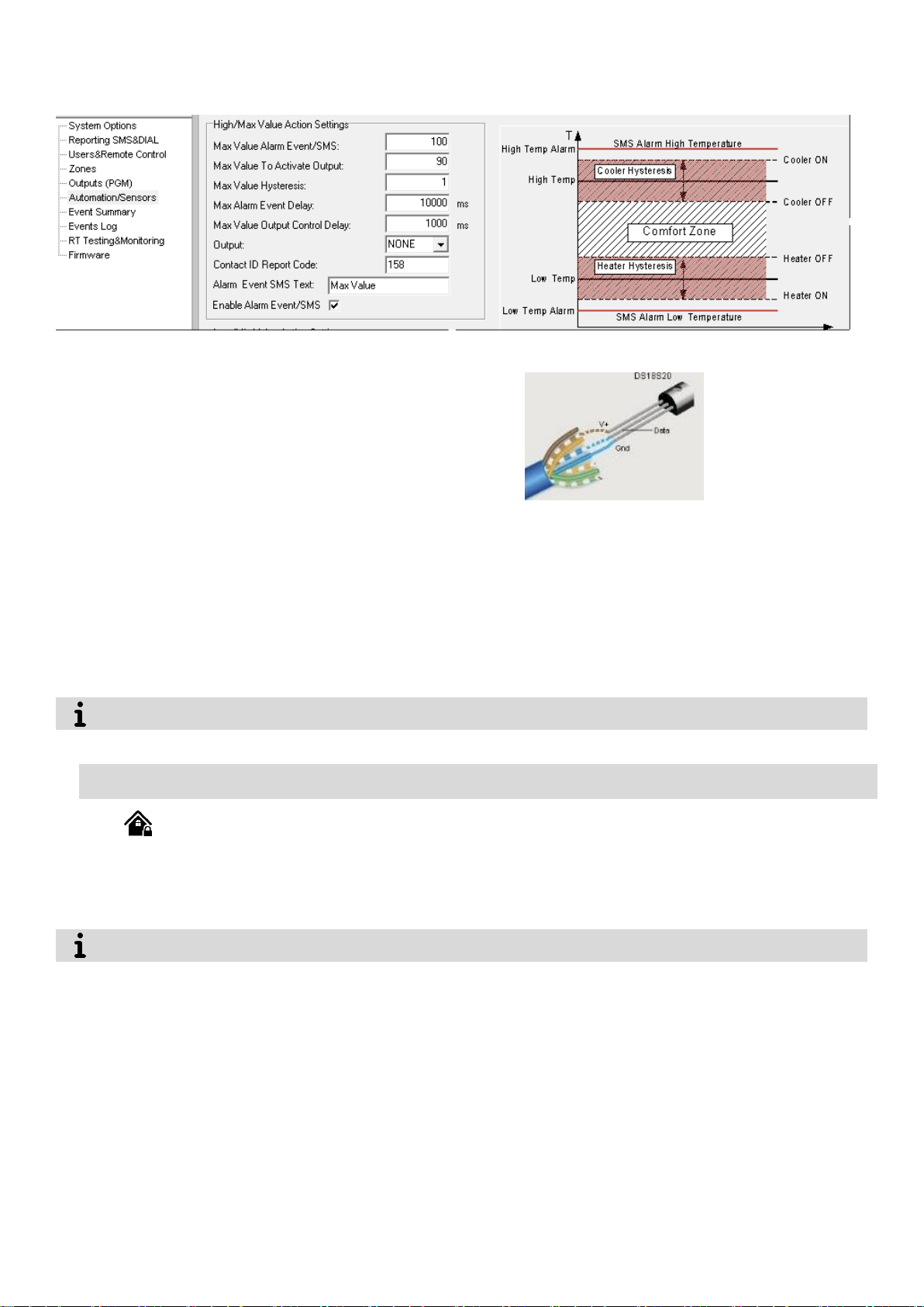
Using cat 5 cable is best and will make it easier to maintain a working 1-wire
network when you expand and add more sensors. The data and ground should
use one twisted pair, for example blue/blue-white. A single wire from another pair
is used for the 3.3 volt supply.
Don't double up wires on the assumption that this lowers resistance and is a 'good
thing', it actually alters the impedance of the network and makes it less reliable.
All unused wires in the cat 5 cable should be left unconnected (don't connect them
to ground).When running a 1-Wire bus, Dallas recommend that you use an
unshielded Cat5 cable for the bus. Do not use shielded cable as the capacitance
increase will upset the network.
Figure 24 Sensor’s connection with Cat5 cable
All wiring entry points are designated by arrows. All circuits are classified UL power limited except for the battery leads. Minimum ¼”
(6.4mm) separation must be maintained at all points between power limited and non-power limited wiring and connections.
It is recommended to use standard motion, fire, and glass breaking sensors. For powering of sensors we recommend to use standard 68 wires cable for, designed for installation of security system.
users and
15. Mark alarm events that you want to receive. Open "Reporting SMS&DIAL" window. Set user phone number, and choose reporting option
Sensor1 - Sensor32 Alarm/Restore. Module will send SMS to user then sensor alarm event occurs
16. Write configuration
If you intend to have a large 1-Wire network, it is important that you design the network correctly, otherwise you will have problems with
timing/reflection issues and loss of data. You must connect each sensor to a single continuous cable which loops from sensor to sensor in turn (daisy
chain). This will reduce potential miss-reads due to reflections in the cable. Each sensor should have a maximum of 50mm (2") of cable connected
off this main network. Even when using this method, connecting more than 10-15 sensors will still cause problems due to loading of the data bus. To
minimize this effect, place a 100-120Ω resistor in series in the data line of each sensor before connecting to the network. The total length of the bus
from 10 to 100m. Depending of cable quality sensors number on bus, and environment noise. There is possibility to connect up to 32 devices.
Begin the installation by mounting additional devices in the cabinet using the stand-offs provided, then mount the cabinet in a dry, protected
area with access to unstitched AC power. Install hardware in the sequence indicated in the following pages. Do NOT apply power until installation is
complete.
3.5. Burglar Alarm sensor zones wiring EOL NO NC
The module GTalarm2 has:
4 analog inputs (In1...In4 (0-10V)) for analog sensors connection. Or can be used or use it as security system‘s zones with selectable type:
NC/NO/EOL/EOL+TAMPER.
2 programmable analog inputs (I/O1, I/O2(0-10V/0-20mA)) for analog sensors control or using as security system‘s zone with selectable
type: NC/NO/EOL/EOL+TAMPER
Connect security system‘s sensors to module as is shown in connection diagrams below
Set the required parameters
Write configuration by pressing „Write“ icon
Page 13
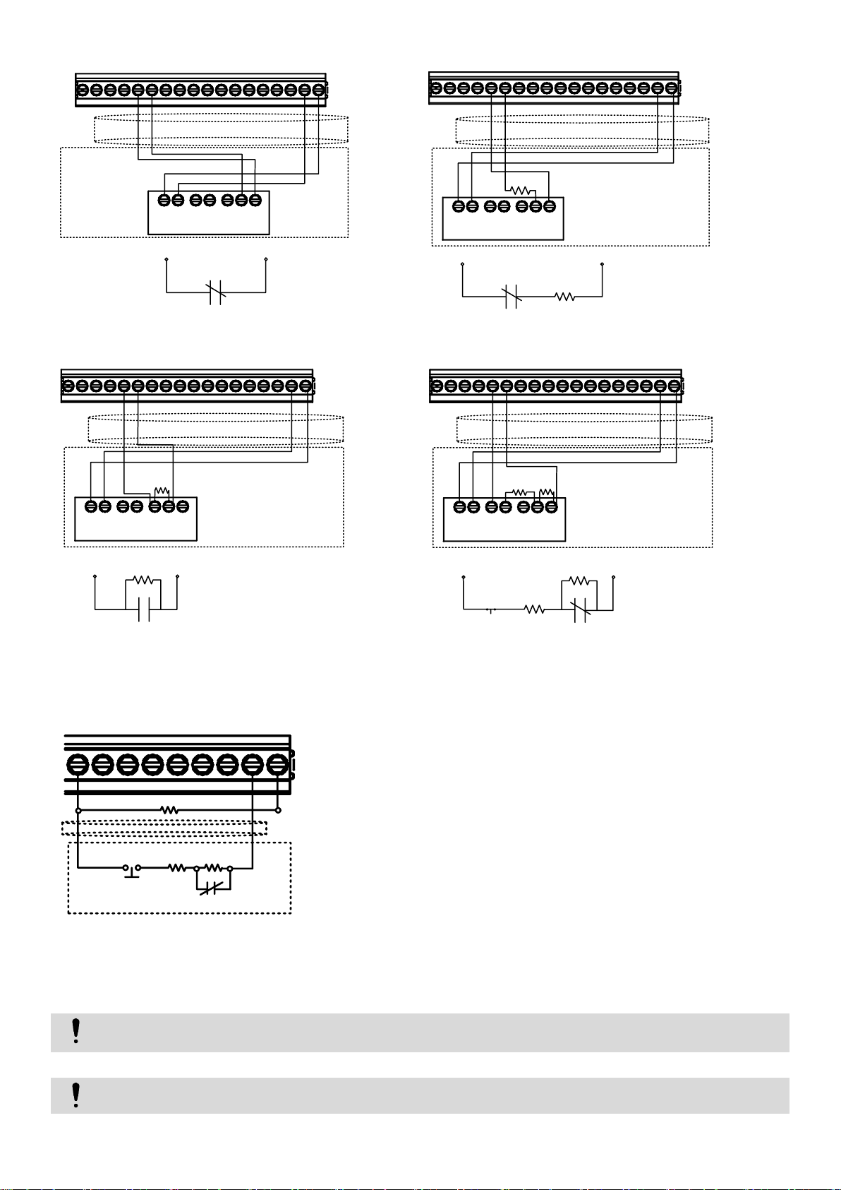
Figure 7 NC Contacts, No EOL
Figure 8 NC, With EOL
Figure 9 NO, With EOL
Figure 10 NC With EOL, With Tamper & Wire Fault
Recognition
Figure 11 EOL+Tamper sensors connection to I/O1, I/O2
Figure 12 NC+Tamper sensors connection to I/O1, I/O2
I/O1, I/O2 do not have internal pull-up resistors. So if you want to connect NO/NC sensors to I/O1 or I/O2 you have to connect 5.1K
resistor between I/O and +VD
Please note. If I/O1 set as 2-wire, you don't need 5.1k resistor.
OUT1
COM
BUS
OUT4
I/O1
IN4
IN3
IN2
D3
OUT2
OUT3
D1
D2
VD+
COM
IN1
I/O2
+
-
COM
NC
TAMP ER
NO
COM
NC
ALARM R ELAY
OUTP UT
sensor
cable
+3.3V
zone input com
NC
OUT1
OUT4
I/O1
OUT2
OUT3
I/O2
COM
BUS
IN4
IN3
IN2
D3
D1
D2
VD+
COM
IN1
+
-
COM
NC
TAMP ER
NO
COM
NC
ALARM RELAY
OUTP UT
sensor
EOL
cable
+3.3V
zone input com
2.2k
NC
OUT1
OUT4
I/O1
OUT2
OUT3
I/O2
COM
BUS
IN4
IN3
IN2
D3
D1
D2
VD+
COM
IN1
+
-
COM
NC
TAMPER
NO
COM
NC
ALARM RELAY
OUTPUT
sensor
EOL
cable
+3.3V
zone input com2.2k
NO
OUT1
OUT4
I/O1
OUT2
OUT3
I/O2
COM
BUS
IN4
IN3
IN2
D3
D1
D2
VD+
COM
IN1
+
-
COM
NC
TAMP ER
NO
COM
NC
ALARM RELAY
OUTP UT
sensor
EOL
cable
+3.3V
EOL
zone input com2.2k
2.2k
tamper
switch
NC
OUT1
COM
BU S
OUT4
I/O1
OUT2
OUT3
VD+
I/O2
5.1k
Sensor
2.2k
2.2k
Tamper
NC
Cable
The module has 2 I/O analogue input/ output circuits I/O1 and I/O2. They also can be used for burglary alarm zones. Input type: NC/NO/EOL/
EOL+TAMPER. I/O1, I/O2 do not have internal pull-up resistors unlike IN1-IN4. So if you want to use I/O as burglar zones to connect NO/NC/EOL
sensors to I/O1 or I/O2 you have to connect external 5.1K resistor between I/O and +VD, as is shown in attached diagram.
Page 14
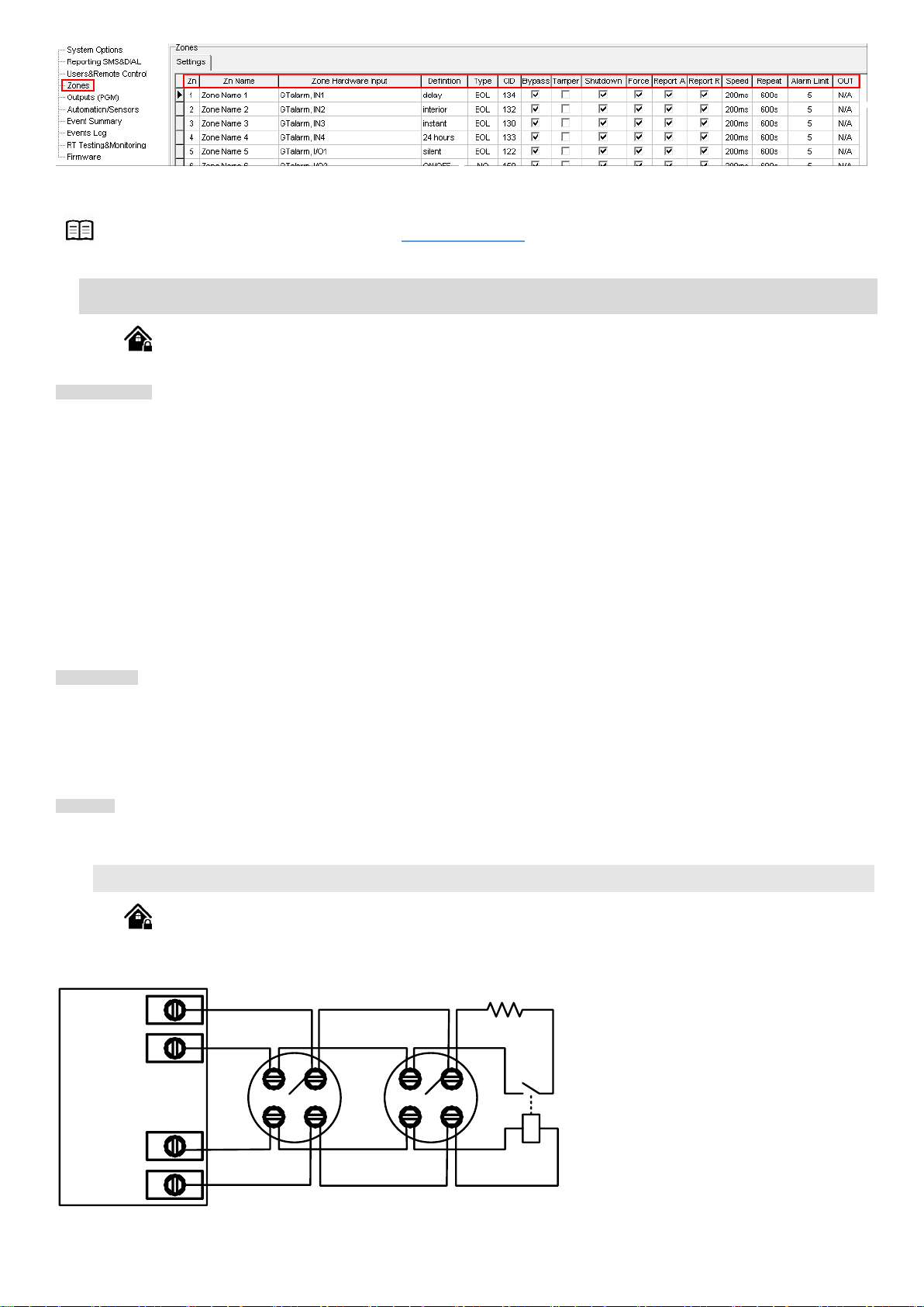
Figure 13 "Zones" window
-
+
-
+
IN1... IN4
COM
OUT1... OUT4
+VD
Smo ke
det ect or
Smo ke
det ector
NO
EOL
2.2k
More information about how to configure the zones: Zones programming
3.6. Guidelines for Locating Smoke Detectors and CO Detectors
The following information is for general guidance only and it is recommended that local fire codes and regulations be consulted when locating and
installing smoke and carbon monoxide alarms.
Smoke Detectors. Research indicates that all hostile fires in homes generate smoke to a greater or lesser extent. Detectable quantities of smoke
precede detectable levels of heat in most cases. Smoke alarms should be installed outside of each sleeping area and on each level of the home.
Additional smoke alarms beyond those required for minimum protection be installed. Additional areas that should be protected include: the basement;
bedrooms, especially where smokers sleep; dining rooms; furnace and utility rooms; and any hallways not protected by the required units.
On smooth ceilings, detectors may be spaced 9.1m (30 feet) apart as a guide. Other spacing may be required depending on ceiling height, air
movement, the presence of joists, uninsulated ceilings, etc.
• Do not locate smoke detectors at the top of peaked or gabled ceilings; dead air space in these locations may prevent smoke detection.
• Avoid areas with turbulent air flow, such as near doors, fans or windows. Rapid air movement around the detector may prevent smoke from entering
the unit.
• Do not locate detectors in areas of high humidity.
• Do not locate detectors in areas where the temperature rises above 38
Where required by applicable laws, codes, or standards for a specific type of occupancy, approved single- and multiple-station smoke alarms shall
be installed as follows:
(1) In all sleeping rooms and guest rooms.
(2) Outside of each separate dwelling unit sleeping area, within 6.4 m (21 ft) of any door to a sleeping room, the distance measured
along a path of travel.
(3) On every level of a dwelling unit, including basements.
(4) On every level of a residential board and care occupancy (small facility), including basements and excluding crawl spaces and unfinished attics.
(5) In the living area(s) of a guest suite.
(6) In the living area(s) of a residential board and care occupancy (small facility).
CO Detectors. Carbon monoxide gas moves freely in the air. The human body is most vulnerable to the effects of CO gas during sleeping hours. For
maximum protection, a CO alarm should be located outside primary sleeping areas or on each level of your home.
The electronic sensor detects carbon monoxide, measures the concentration and sounds a loud alarm before a potentially harmful level is reached.
Do NOT place the CO alarm in the following areas:
• Where the temperature may drop below -10ºC or exceed 40 ºC.
• Near paint thinner fumes.
• Within 5 feet (1.5 meters) of open flame appliances such as furnaces, stoves and fireplaces.
• In exhaust streams from gas engines, vents, flues or chimneys.
• In close proximity to an automobile exhaust pipe; this will damage the detector.
GTalarm2. Begin the installation by mounting additional modules in the cabinet using the stand-offs provided, then mount the cabinet in a dry,
protected area with access to un switched AC power. Install hardware in the sequence indicated in the following pages. Do NOT apply power until
installation is complete.
o
C (100oF) or falls below 5oC (41oF).
3.6.1. [4-Wire] Smoke detector Wiring
Connect the 4-wire smoke detectors and a relay as shown in the figure below.
Figure 14 4-Wire Smoke Detector Installation
Page 15
More information about how to configure 2-Wire Smoke detectors: 2-wire smoke detectors programming
OUT1
COM
BU S
OUT4
I/O1
OUT2
OUT3
VD+
I/O2
-
+
-
+
2.2k
Smoke
detector
EOL
Smoke
detector
Install the 4-wire smoke detectors with 18 gauge wire. If power is interrupted, the relay causes the control panel to transmit the Fire Loop Trouble
report. To reset (unlatch), connect the smoke detector’s negative (-) to a PGM.
The parameters of the zone should be defined as a “Fire Zone”. If a line short occurs or the smoke detector activates, whether the system is
armed or disarmed, the control panel will generate an alarm. If the line is open, the “Zone Fault” report code is sent to the monitoring station or to the
user, if programmed.
1. Connect the [4-wire] smoke detector.
2. Connect the power supply.
3. Install SERA2 software.
4. Go to “Burglar Alarm Zones” window. Double press on required input. Set “Zone definition” to “Fire”.
5. Write configuration by pressing “Write” icon.
3.6.2. [2-Wire] Smoke Detector Wiring to I/O Inputs
The 2-wire Smoke zone on the module is the only zone in the system that can have 2-wire smoke detectors as Fire Alarm initiating devices. This
zone is an end-of-line EOL 2.2K resistor type and can accommodate up to 30 compatible 2-wire smoke detectors. The zone is fixed as a 2-wire smoke
zone. I/O 2-wire smoke zone is trouble supervised zone. The zone wiring is supervised by the control panel.
The parameters of the zone should be defined as a “Fire Zone”. I/O1 and I/O2 can be defined as a 2-wire smoke detector input if a line short
occurs or the smoke detector activates, whether the system is armed or disarmed, the control panel will generate an alarm. If the line is open, the
“Zone Fault” report code is sent to the monitoring station or to the user, if programmed.
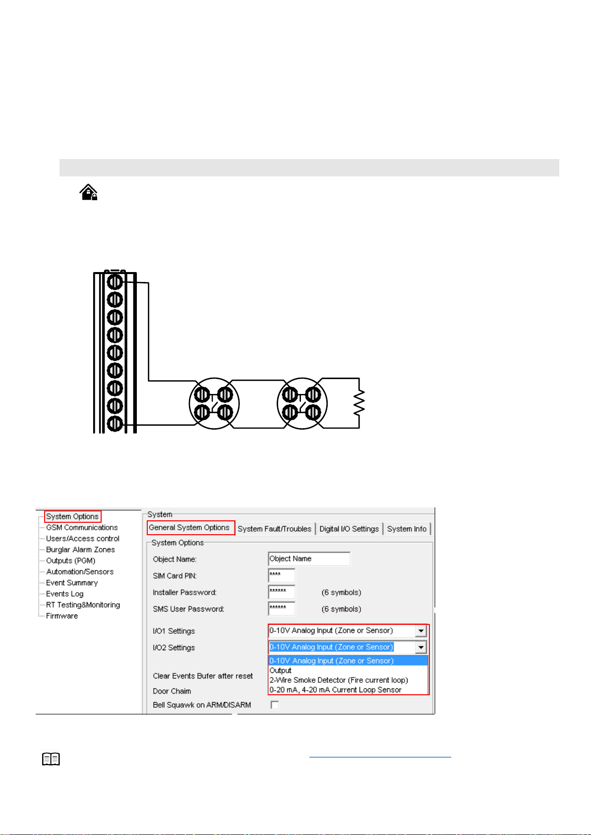
Figure 15 2-wire smoke detector wiring diagram
1. Connect the [2-wire] smoke detector (current sensor).
2. Connect the power supply.
3. Install SERA2 software.
4. Go to “System Options> General System Options” from the menu and select 2-Wire Smoke Detector (Fire current loop)
Figure 16 How to find System Options> General System Options window
5. In the Zone table set I/O1 definition to “Fire”
6. In the output table I/O1(20mA) set to “Fire Sensor”
Page 16
7. Write configuration by pressing “Write” icon.
I/O1, I/O2 do not have internal pull-up resistors. So if you want to connect NO/NC sensors to I/O1 or I/O2 you have to connect 5.1K
resistor between I/O and +VD
If I/O1 set as 2-wire, don’t need connect 5.1k resistor to +VD.
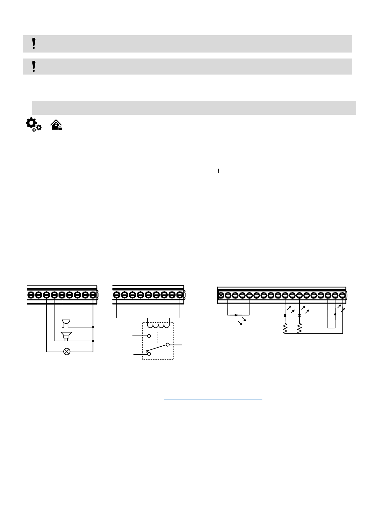
Fig. 1 OUT1-OUT4 Open
drain 1000 mA connection
Fig. 2 Relay connection to OUT1OUT4, I/O1, I/O2 20mA
Fig. 3 example of LED connection to output
-
+
-
+
OUT1
COM
BUS
OUT4
I/O1
OUT2
OUT3
VD+
I/O2
Flash
Bell
Buzzer
OUT1
COM
BUS
OUT4
I/O1
OUT2
OUT3
VD+
I/O2
NO
NC
com
OUT1
COM
BUS
OUT4
I/O1
IN4
IN3
IN2
D3
OUT2
+3.3V
OUT3
D1
D2
VD+
COM
IN1
I/O2
2.2k
2.2k
3.7. Outputs. Bell & PGM Wiring
The module GTalarm2 has:
4 open drain (1A) outputs: OUT1 (1A)… OUT4 (1A). The outputs can be used for siren, relay, lamp connection. These outputs can be
controled via short call or sms. Output operation algorithms: Automation /CTRL, Siren, Buzzer, ARM state, Zones OK, Light Flash, inverting,
pulse mode
2 open drain (20mA) outputs: I/O1 (20mA)… I/O2 (20mA). These outputs can be used for solid state relays, LED, to control devices up to
20mA.
3 outputs: D1 (10mA, Max Voltage 3,3V) for LED, solid state relays control. Max voltage 3,3V
1 programmable output BUS. Voltage 8-15V, Current 20mA
OUT1… OUT4 max current – (-V) 1000 mA.
All outputs can be controlled via short call DIAL or via SMS message. This feature may be used for gate opening, ignition locking etc.
Output alarm parameters may be programmed.
Programmable algorithms for outputs operation: CTRL/SMS/DIAL, SIREN, BUZER, ARM state, Zones OK, Light Flash, inverting, pulse
Output switch to ground when activated from the module. Connect the positive side of the device to be activated to the VD+ terminal. Connect the
negative terminal to the selected output.
mode
1. Connect devices to the selected outputs as shown in the figures below. For sound signaling we recommend to use siren DC 12V up to
1500mA. It is recommended to connect the siren to the system by using 2 x 0,75 sq. mm double insulation cable. Auxiliary BUZZER is
recommended to be installed inside the premises not far from the entrance. Buzzer operates together with the main siren also when the
system starts calculating the time to leave the premises and the time till alarm response of the security system after entering the premises
(see clause 7.1). It is possible to use buzzer of hit point PB12N23P12Q or similar modified piezoelectric 12V DC, 150mA max Buzzer.
Standard AC/DC adapter with the voltage 10V-14V and current >=1A might be used to powering the module
1. Install SERA2 software. For more information look at SERA2 Uploading/Downloading Software
2. Connect the module to the computer via mini USB cable.
3. Go to Outputs (PGM) window in the SERA2 software
4. Parameters of the selected output should be set:
5. output operation description (OUT definition): disable, bell, buzzer, flash, system state, ready, automation/ CTRL, AC OK, battery OK, ARM/
DISARM, alarm indication, lost primary channel, lost secondary channel, fire sensor, RH sensor trouble.
6. State type: flash, timer, steady mode.
7. If necessary output operation might be inverted.
8. Write configuration by pressing write icon
Page 17
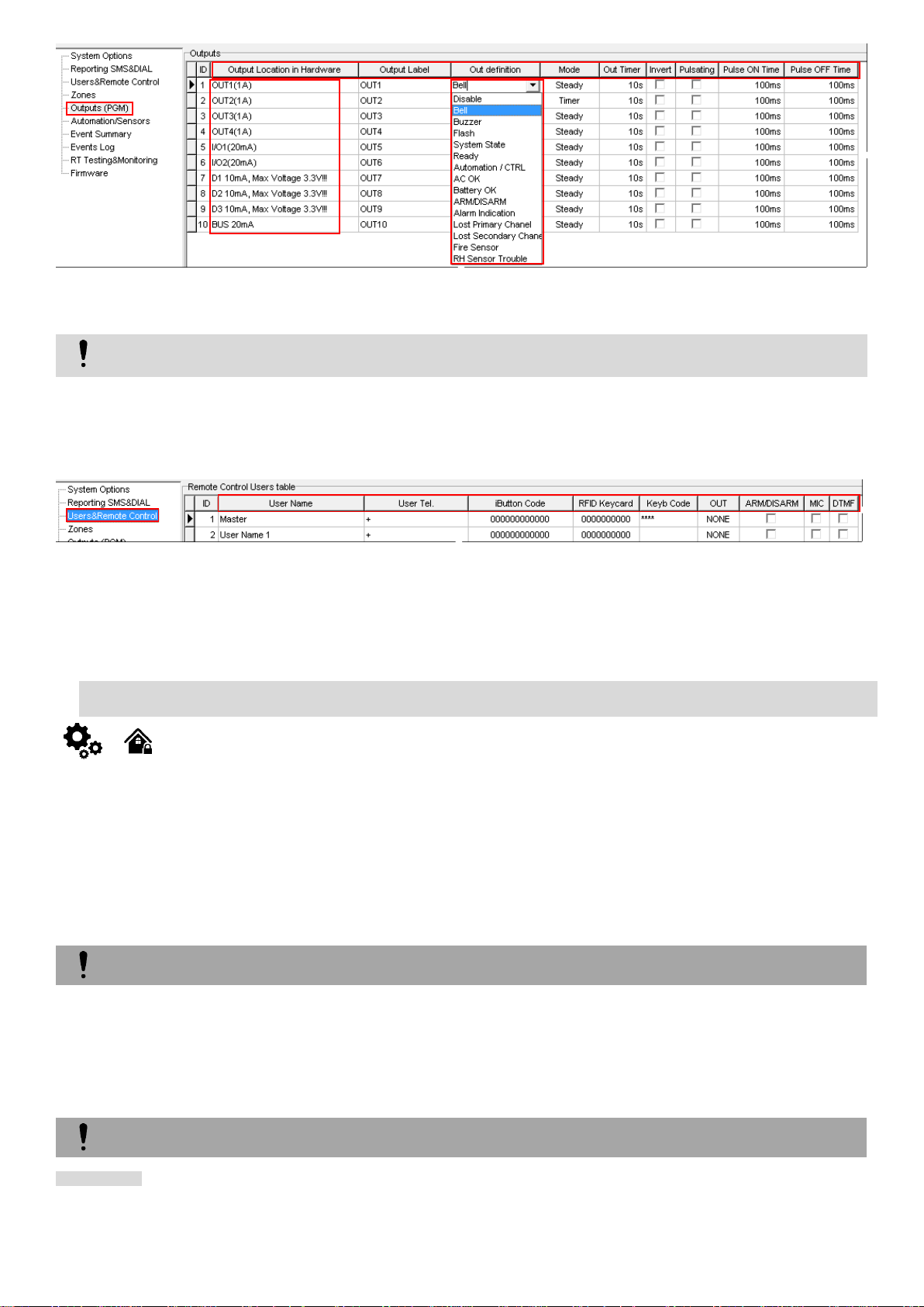
Figure 17 How to find Outputs (PGM) window
Outputs can be controlled only in Automation/ CTRL mode.
The alarm will be caused even if a tamper is violated while the system is disarmed
Due to security reasons it is highly recommended to restore the violated zone/tamper before arming the system.
9. If you need to control outputs by short call or sms, go to “Users & Remote Control” window and enter telephone numbers of users, who will
be able to control selected outputs via free short call.
10. Write configuration by pressing write icon
Figure 18 How to find Users& Remote control window
In order to control big power alternating current equipment, it is comfortable to use solid state relays.
Standard AC/DC adapter with the voltage 10V-14V and current >=1A might be used to powering the module.
3.8. Access control. Arming/ disarming methods
General operation description
When the system is being armed, it will initiate the exit delay countdown intended for the user to leave the secured area. During the countdown
period the buzzer will emit short beeps. By default, if there is at least 1 violated zone or tamper, the user will not be able to arm the system until the
violated zone or tamper is restored. In case it is required to arm the alarm system despite the violated zone presence, the violated zone can be
bypassed or Force attribute enabled.
After the system is armed and if a zone (depending on type) or tamper is violated, the system will cause an alarm. During the alarm, the siren/bell
will provide an alarm sound along with the buzzers of the keypads. By default, the system will also makes a phone call and send an SMS text message
containing the violated zone or tamper number to a listed user phone number and indicate the violated zone or tamper number on the keypad. If
another zone or tamper is violated or the same one is restored and violated again during the alarm, the system will act as mentioned previously, but
will not extend the alarm time.
After the user enters the secured area, the system will initiate the entry delay countdown intended for system disarming. During the countdown
period, the buzzer will emit a steady beep.
When the system is successfully armed or disarmed, it replies with confirmation by SMS text message.
Arming process:
The system features the following methods to carry out arming and disarming process:
Free of charge phone call
SMS text message
Wiegand keypad user code
Wiegand RFID key card, keyfob
iButton key
If ready (no violated zone/tamper), the system will arm.
If unready (violated zone/tamper is present), the system will not arm and provide a list of violated zones/tampers by SMS text message to
user phone number. In such case the user must restore all violated zones and tampers before arming the system. Alternatively, the violated
zones can be bypassed, disabled or a Force attribute enabled, and the tampers can be disabled when arming. The system initiates the exit
Page 18
delay countdown intended for the user to leave the secured area. When the security system is to be turned in ARM mode, the bell will beep
Arm/Disarm by call
It is possible to arm, disarm the system and turn OFF the alarm by dialing the system‘s phone number from any of 800 available user
phone numbers The system ignores any incoming calls from a non-listed phone number .The phone call is free of charge as the system
rejects it and carries out arming/disarming procedure afterwards. If there is more than one listed user dialing to the system at the same
time, the system will accept the incoming call from the user who was the first to dial while other user (-s) will be ignored. To disable/enable
arming or disarming for certain listed user phone numbers, please mark near ARM/DISARM in the “Users & Remote control” window
Arm/Disarm by sms
The system ignores any incoming SMS text messages from a non-listed phone number as well as it rejects the SMS text messages
containing wrong SMS password even from a listed user phone number. To arm the system by SMS text message, send the following
text to the system‘s phone number USER 000000˽030˽ST
030= command code (Change security system’s mode (ARM/DISARM/STAY/SLEEP)
ST = Security system mode 0-DISARM, 1-ARM ,2-STAY ,3-SLEEP
Arm/Disarm by keypad
To arm/ disarm the system by Wiegand Keypad, enter User/Master Code
To cancel the arming process: Enter the user/master code again during exit delay countdown.
Disarming the System and Turning OFF the Alarm To disarm and turn OFF the alarm, enter any out of available user codes or master
code using the number keys on the keypad.
Arm/Disarm by iButton key
To arm or disarm the system and turn OFF the alarm, touch the iButton key reader by any of 800 available iButton keys. When the
iButton is touched to the iButton key reader for arming/ disarming, the system will proceed arming/ disarming process.
Arm/Disarm by RFID key card, keyfob
To arm/ disarm the system with RFID keycard, touch 1 of 800 RFID keycard to the Wiegand keypad. When the RFID keycard is touched
to the reader for arming/ disarming, the system will proceed arming/ disarming process.
More information about how to configure Arming/ Disarming: DISARM /ARM/SLEEP/STAY
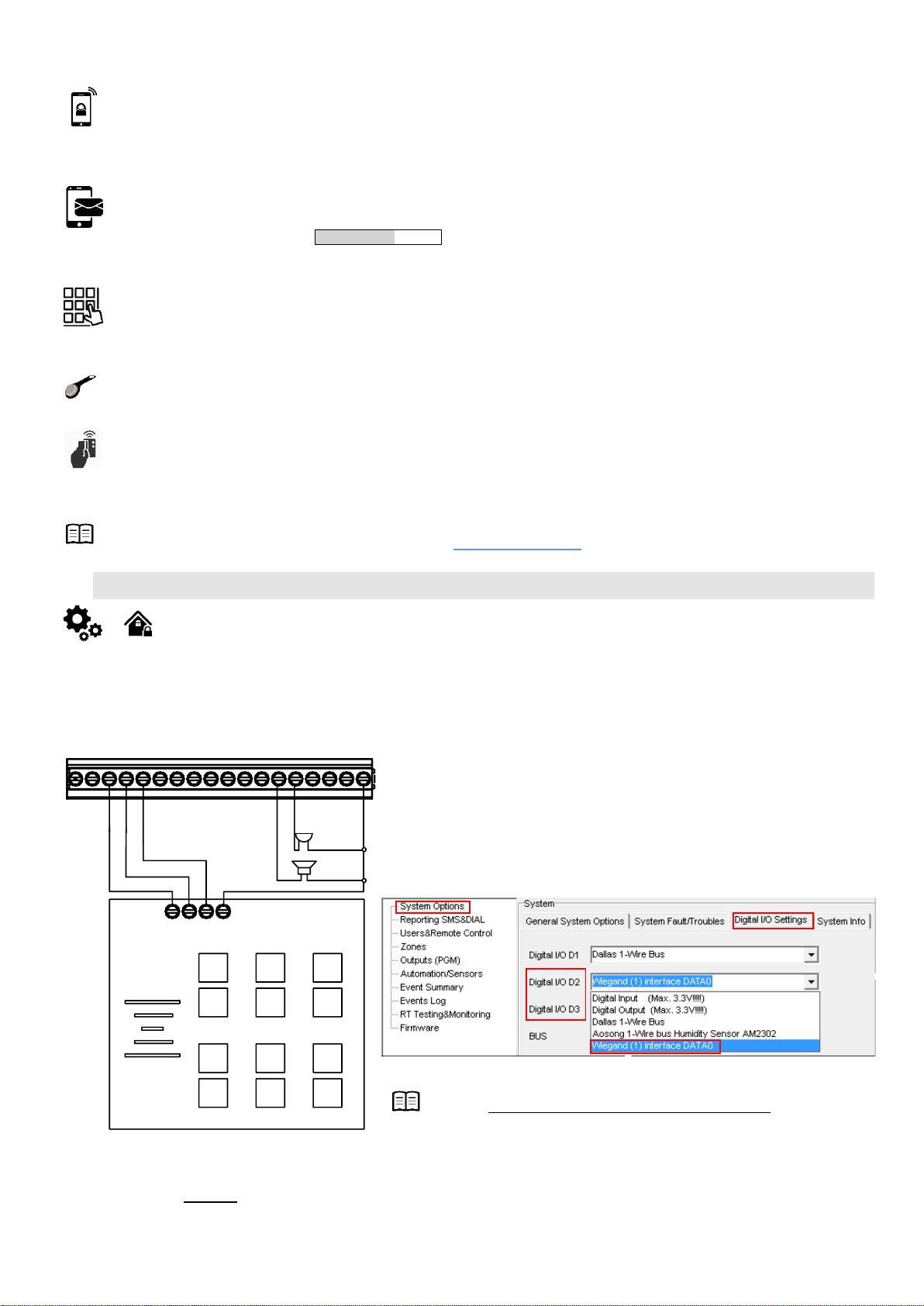
Figure 3-19 Wiegand keypad connection
Connect Wiegand keypad as shown in the Fig
How to configure Wiegand keypad:
1. Connect Wiegand keypad as shown in the Fig
2. Install SERA2 software.
3. Connect the module to the computer via mini USB cable.
4. „Go to System options“> Digital I/O Settings
5. Set Digital I/O D2 to Wiegand interface Data0
6. Set Digital I/O D3 to Wiegand interface Data1
7. Write configuration
Figure 20 How to find "System Options > Digital I/O Settings window
More information about how to configure Wiegand Keypad & RFID Card
Reader: Wiegand Keypad & RFID card reader programming
OUT1
COM
BUS
OUT4
I/O1
IN4
IN3
IN2
D3
OUT2
+3.3V
OUT3
D1
D2
VD+
COM
IN1
I/O2
1 2 3
4 5 6
7 8 9
esc
0
ENT
-
+
-
+
Bell
Buzzer
com
12 V
D1
D0
once, when in DISARM mode - the bell will beep twice.
3.8.1. Wiegand Keypad & RFID Card Reader Wiring
Wiegand bus specifications:
26bit Wiegand (Default);
8bit key press code
It is possible to enter manually iButton or RFID Keycard codes. In that case, you have to:
Install SERA2 software
1. Go to “Users& Remote Control” table.
Page 19
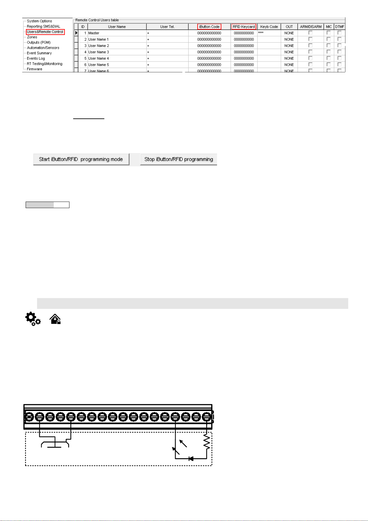
Figure 21 How to find Users&Remote Control window
If you need to enter iButton learning/ deleting mode by
sending sms message, you have to send:
INST123456˽063˽S
INST = Install. Configuration of the parameters.
123456= Installer‘s password
˽= Space character
063= command code (iButton keys learning/deleting mode)
˽= Space character
S=iButton keys entering/deletion mode.
0- Disable iButton keys learning mode,
1- Enable iButton keys learning mode,
2- iButton keys deleting mode,
3- Delete these keys from memory, which will be
touched to the reader.
When you receive a message into your mobile phone in relation to activation
of iButton key programming mode, touch the key to the reader and its unique code
will recorded into system memory. Buzzer will notify you about successful
recording by beeping twice. The system allows to associate up to 800 iButton
keys. Each time when touching the key, the system records its code till all
desirable keys will be recorded. If during 2 minutes not a single iButton key will
not be learned, the system will automatically exit keys learning mode. After
finishing programming of the keys, you might send SMS message.
You can disable recording of new keys into memory. In the event of failure to
send this message, ARM/DISARM of the system via iButton key will not operate.
Control functions for all newly associated keys will be assigned according to
MASTER key. For example: If MASTER key will control Out1, all newly associated
keys will also control Out1.
You can delete all iButton keys from the memory. If you have the key, that
you want to delete from the memory, you have to send sms and touch the key to
the reader. 2 minutes later, the module will deactivate the keys deletion mode.
OUT1
COM
BU S
OUT 4
I/O1
IN4
IN3
IN2
D3
OUT 2
+3.3V
OUT3
D1
D2
VD+
COM
IN1
I/O2
system state
2. Enter iButton or RFID Keycard codes for users.
3. Select iButton or RFID Keycard action OUT/ARM/DISARM, etc.
Write the configuration into the module by pressing “Write” icon
It is possible to enter automatically iButton or RFID Keycard codes.
Association of iButton keys or RFID Keycards is carried out by activating special programming mode - by sending SMS or by pressing „Learn
iButtons/RFID mode“in the SERA2 configuration program.
If you need to enter iButtons learning mode by SERA2 software, you have to:
Install SERA2 software.
1. Go to the “System options> General system options” and press “Start iButton/RFID programming mode” to start entering iButton keys.
2. Press “Stop iButton programming” to stop entering iButton keys.
Figure 22 the example of Start/Stop iButton/RFID programming mode
3. Write configuration by pressing “Write” icon.
3.8.2. iButton keys
Maxim-Dallas iButton keys (iButton DS1990A – 64 Bit ID)) can be used to ARM/DISARM security panel or control selected output. Up to 800
iButton keys can be assigned to the system.
The First iButton key may be learned (recorded) by touching it to the reader. Without the need to send any SMS. The system will notify about
successfully recording of the key into memory by shortly beeping twice via buzzer. The system will automatically assigns control function
(ARM/DISARM).
The first key is the main key (MASTER) other keys might be learnt thus:
1. To enter key codes directly into configuration users table.
2. By pressing Learn iButton button in the “System Options” window.
3. By sending SMS with command for new keys learning.
4. By using MASTER key
Figure 3-23 The example of iButton connection
The total length of the bus from 10 to 100 m. Depending of cable quality, and environment noise.
Page 20
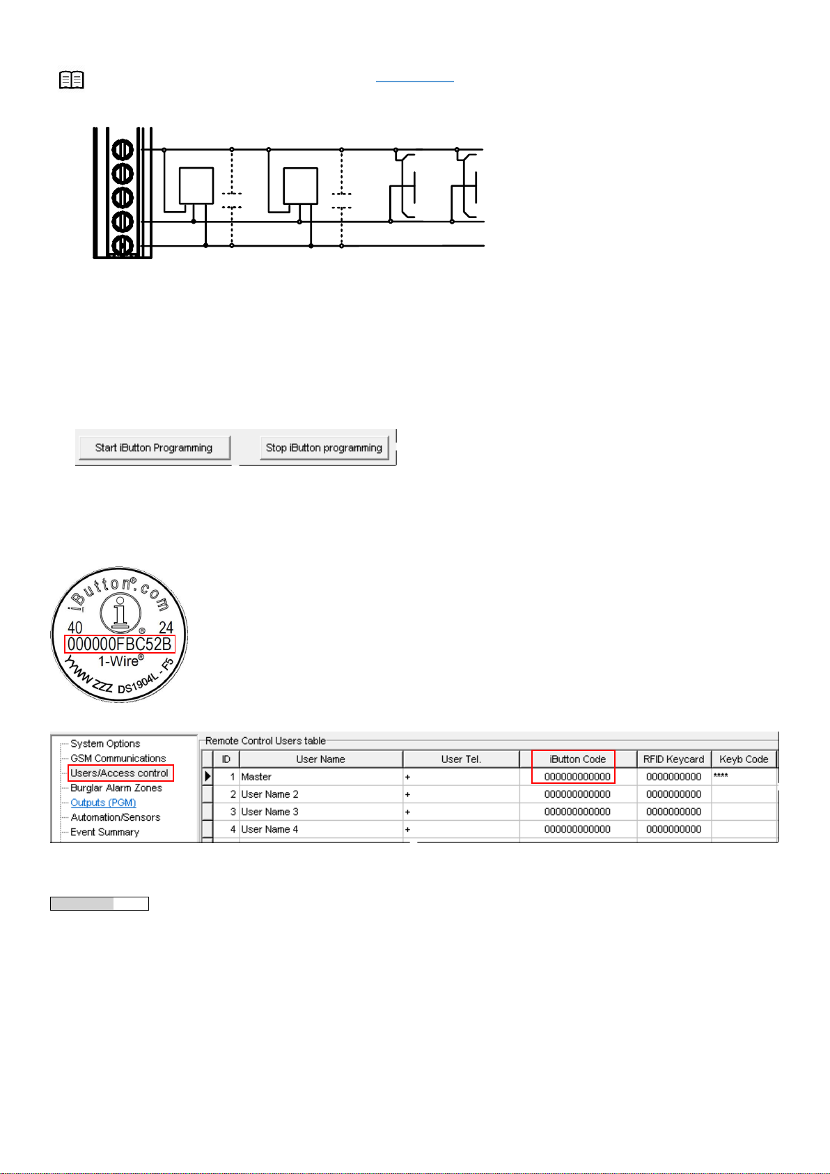
LED is without resistor. External resistor required.
More information about how to configure iButton keys: iButton keys & RFID programming
+3.3V
D3
D1
D2
COM
D1...D3
CZ Dallas ReaderDS18B20
470-4700µF 470-4700µF
Figure 24 The connection of iButton readers together with temperature sensors, on the same bus
Association of keys is carried out by activating special programming mode by sending SMS or by pressing „Learn iButtons“ in the configuration
program.
Enter iButtons learning mode by SERA2 software:
1. Install SERA2 software.
2. Go to the “System options> General system options” and press “Start iButton programming” to start entering iButton keys or “Stop iButton
programming to stop entering iButton keys.
3. Write configuration by pressing “Write” icon.
Enter iButtons manually in SERA2 software:
1. Install SERA2 software.
2. Go to the “Users/ Access control” window and enter manually iButton codes. It is the code in red rectangular in the picture below.
Figure 25 How to find iButton code on the iButton key
Figure 26 How to find "Users/ Access control window and where enter iButton codes.
iButton learning/ deleting mode by sending sms message:
INST123456˽063˽S
INST = Install. Configuration of the parameters.
123456= Installer‘s password
˽= Space character
063= command code (iButton keys learning/deleting mode)
˽= Space character
S=iButton keys entering/deletion mode.
0- Disable iButton keys learning mode
1- Enable iButton keys learning mode
2- iButton keys deleting mode.
Page 21
3- delete these keys from memory, which will be touched to the reader
The module must be powered with (+12V >500 mA) voltage, it should have inserted SIM card (with replenished account and removed
PIN CODE REQUEST). Module must be connected to the PC via micro USB cable
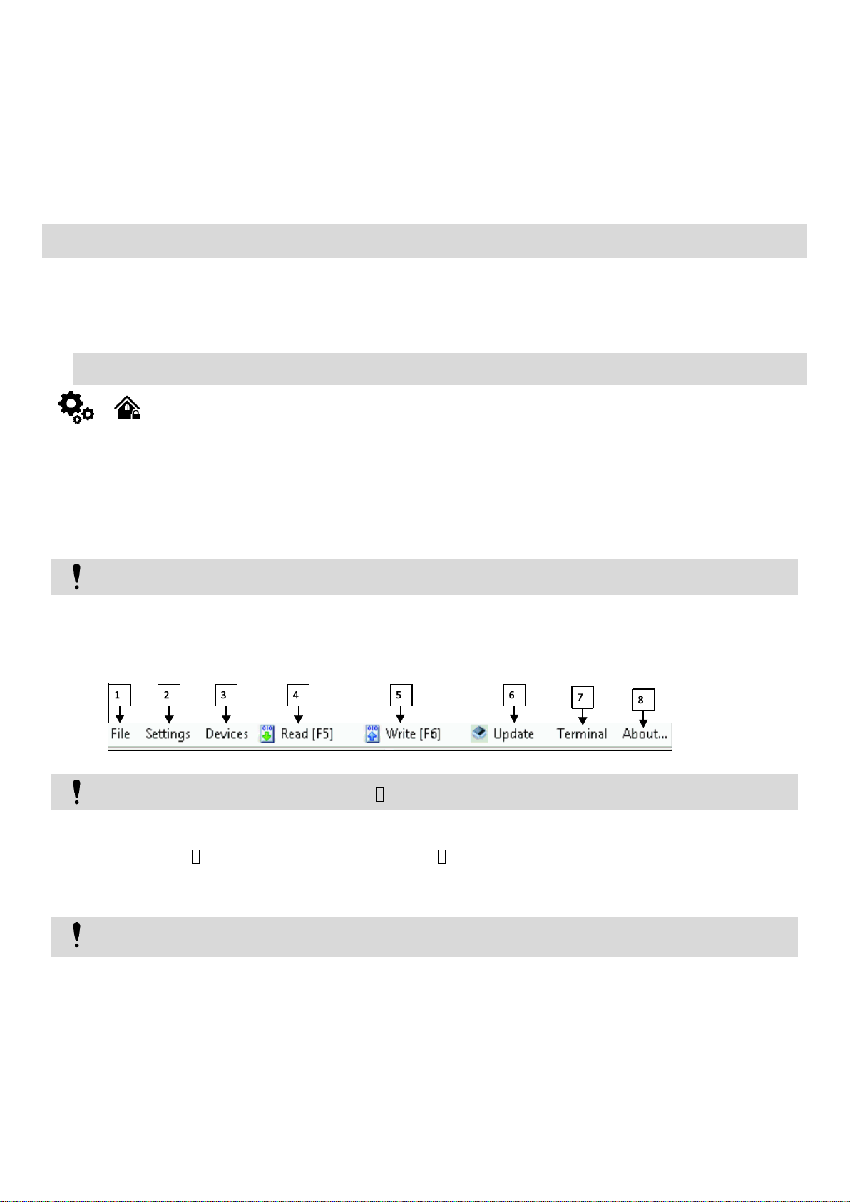
Each time after configuring the module press Write 5 icon thus the software SERA2 will write configuration changes into the module!
If you want to receive software updates, go to Settings and mark “Check for Updates Automatically”. When new update will be available,
the program will inform you, and you have to start the update. After that you have to connect the module to the computer via mini USB
cable. You have to write this update to the module GTalarm2 by pressing “Update” in the bottom line in SERA2 software.
Figure 27 The meaning of icons
When you receive a message into your mobile phone in relation to activation of iButton key programming mode, touch the key to the reader and
its unique code will recorded into system memory. Buzzer will notify you about successful recording by beeping twice. The system allows to associate
up to 800 iButton keys. Each time when touching the key, the system records its code till all desirable keys will be recorded. If during 2 minutes not a
single iButton key will not be learned, the system will automatically exit keys learning mode. Or after finishing programming of the keys, you might
send SMS message.
You can disable recording of new keys into memory. In the event of failure to send this message, ARM/DISARM of the system via iButton key will
not operate. Control functions for all newly associated keys will be assigned according to MASTER key. For example: If MASTER key will control
OUT1, all newly associated keys will also control OUT1.
You can delete all iButton keys from the memory. If you have the key, that you want to delete from the memory, you have to send sms and touch
the key to the reader. 2 minutes later, the module will deactivate the keys deletion mode.
4. Programming
listed user phone numbers. More
This software simplifies system configuration process by allowing to use a personal computer in the process.
In order to configure and control the system by SMS text message, send the text command to the GTalarm2 phone number from one of the
SERA2 software configuration tool is intended for the module GTalarm2 configuration locally via USB port or remotely via GPRS network.
4.1. SERA2 Uploading/Downloading Software
We recommend programming the module GTalarm2 with SERA2 software
1. Open the folder containing installation of the software SERA2. Click the file „SERA2 setup.exe“
2. If installation directory of the software is OK, press [Next]. If you would like to install the software in the other directory press [Change],
specify other installation directory and then press next>.
3. Check if the correct data are entered and press Install
4. After successful installation of the software SERA2, press [Finish]
Connection of the module to your PC
Work with the software SERA2
Start the software SERA2. Go to „Start“> „All programs“> „SERA2“> „SERA2 “or go to installation directory and click „SERA2.exe“.
If you are sure that the module is fully connected to PC and power supply, please go to Devices > GTalarm v2
After configuration of the module, all settings may be saved at PC. It enables to save time, when next time the same configuration will be used – it
will not be necessary again to set the same parameters. If you want to save that is already recorded by the module, firstly you must read configuration
of the module. Press Read 4 icon. In order to save configuration go to File 1 then press “Save As” or “Save”. Enter configuration parameter in the
displayed table and press „OK“
In order to start saved configuration go to File then press Open
It allows to copy the same programmed content into as many modules as required.
Page 22
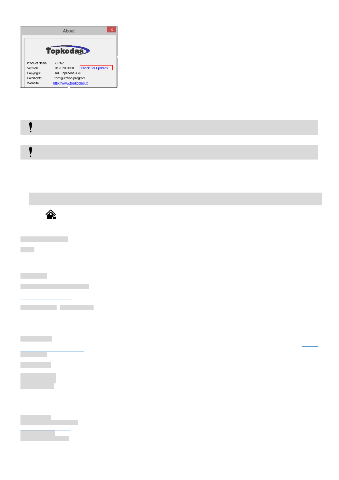
If you want to update the module manually, got to “About” and press “Check for updates”
Press “Read” icon first to read the configuration from the module, the press “File>Save us” and save the configuration.
Save the Events Log file and send these files with the question to the seller.
Figure 28 How to update the module manually
If you need to contact the seller with the questions about the configuration, you have to:
These steps will let better understand the problem and will reduce the time to find the solution.
4.2. Security Programming Worksheets
The most important information due to security system of the module GTalarm2
Programming methods. It is recommended to configure the module via SERA2 software. It is possible to configure the module via sms messages if
needed.
Zones. The control panel includes 4 input terminals and 2 selectable input or output terminals for use with traditional hardwired door contacts, smoke
detectors and/or motion detectors. The control panel also supports hardwire zone expansion modules. If the zone is not used, it should be disabled
via SERA2 software. Zone types, Zone speed; Event repeat timeout; Max alarm count; Zone Alarm action: enable, disable or activate selected output;
Should be enabled or disabled: Alarm report; Restore report; Tamper; Bypass; Shut down if max alarm count; Zone force ARM also should be set in
the SERA2 software Zones window.
Fire Circuits. Assign the smoke detectors to the GTalarm2 module and configure the module via SERA2 software. Mark Set I/O as 2-Wire (Fire Loop)
in the General system options. Configure I/O1 definition to “Fire” in the Zones table. In the output table I/O1(20mA) set to “Fire Sensor”.
Tamper Recognition. Alarm types. Select the method how does the control panel will operate after tamper recognition: 1) Tamper Disabled, 2) Trouble
when disarmed / alarm as per zone when armed, 3) Trouble always 4) Audible alarm when disarmed / alarm as per zone when armed System Fault/
Troubles Programming Tamper Recognition follows the zone’s bypass definition. This means that the control panel will not perform any action if a
tamper or wire fault occurs on a bypassed zone.
Arming/Disarming. Entry/Exit Delay. When the system is being armed, it will initiate the exit delay countdown intended for the user to leave the
secured area. By default, if there is at least 1 violated zone or tamper, the user will not be able to arm the system until the violated zone or tamper is
restored. In case it is required to arm the alarm system despite the violated zone presence, the violated zone can be bypassed or Force attribute
enabled. After the system is armed and if a zone (depending on type) or tamper is violated, the system will cause an alarm. If another zone or tamper
is violated or the same one is restored and violated again during the alarm, the system will act as mentioned previously, but will not extend the alarm
time. After the user enters the secured area, the system will initiate the entry delay countdown intended for system disarming.
Restrict arming: By default, it is allowed to arm the system while the following system faults are present: Low battery. Battery dead or missing. Battery
failed. Date/time not set. GSM connection failed. GSM/ GPRS antenna failed. Tamper trouble If needed, restrict arm, when such trouble occur System
Fault/ Troubles Programming
Bell Squawk: The control panel can activate the bell output briefly causing the bell or siren to squawk to alert users that a partition is being armed,
disarmed or that an Entry or Exit Delay was triggered.
Access control: The system features the following methods to carry out arming and disarming process: Free of charge phone call; SMS text message;
Wiegand keypad; keycard; iButton key
Bell/alarm Output When an alarm condition is detected, the module can trigger BELL output enabling any bells or sirens connected to it.
Bell Cut-off Timer After an audible alarm, the bell or siren will stop once the module is disarmed or when the Bell Cut-Off Timer has elapsed.
Event Reporting the module verifies if a zone alarm and restore events assigned to the user’s phone number. If yes, the module send alarm event to
the user.
If needed, reporting to the central monitoring station (CMS) can be activated. Then if the alarm occur, the alarm events will be reported to the central
monitoring station.
The system can transfer these events to the user or to the CMS: Zone alarm/restore events, Tamper alarm/restore events, Arming/Disarming events,
Trouble events.
SIA IP protocol the module communicates with the CMS via SIA IP protocol (ANSI/SIA DC-09-2007; configurable as encrypted and non-encrypted).
Power Failure Report Delay The control panel will delay the transmission of the AC Failure report code by the period that is set System Fault/
Troubles Programming
Auto Test Report The control panel can transmit the test report code every hour or after a period of time.
Programmable Outputs. The module has four PGM outputs, max current – (-V) 1000 mA. The PGM Activation Event determines which event will
activate the PGM. Once the PGMs are activated, they can deactivate when another event occurs or after a period of time. The PGM Deactivation
Event determines which event will return the PGM to its original state. When the PGM Deactivation Option is enabled, the PGM Timer determines
Page 23
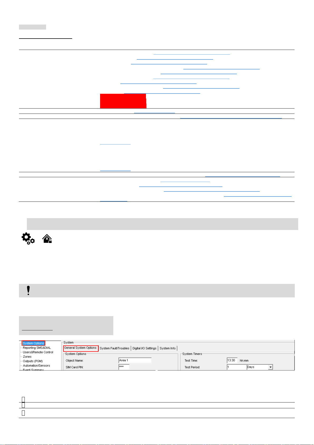
how many seconds or minutes the PGM remains activated. Programmable algorithms for outputs operation: CTRL/SMS/DIAL, SIREN, BUZER, ARM
Set general system details
System Times (entry delay): General system options programming
Installer Password: General system options programming
User Password: General system options programming
System Options (Bell squawk, Door Chain ): General system options programming
Test Transmission Time of Day: General system options programming
Periodic Test Transmission: General system options programming
Set Clock: General system options programming
Restore Control Panel to Default: General system options programming
Auto-reArm: General system options programming
Panel Version Displayed
Expansion Programming
Installer Walk Test Mode
Set zones parameters
Zone Definitions: Zones programming
Set access control details
Wiegand Keypad & RFID Reader settings: Wiegand Keypad & RFID card reader programming
Set Outputs (PGM)
PGM Output Attributes Programming:
Outputs. Bell & PGM programming
PGM Output Timer:
Outputs. Bell & PGM programming
Set reporting to user mobile phone
Maximum Dialing Attempts to Each Telephone Number: Reporting to the user‘s mobile phone
Set reporting to Central monitoring
station details
Reporting codes programming: Event Summary (Events)
GPRS/IP/TCP/UDP: GPRS/ IP/ TCP/ UDP details programming
Central monitoring station details: Central Monitoring Station details programming
Reporting to primary or backup central monitoring stations details: Central Monitoring Station details
programming
If the module has been connected first time to the power supply, or power supply has been disconnected for a long time, the time of
the module should be set again.
System Options > General system Options
The general system options settings let you control system options, system general
settings, systems timers, let you program iButton keys and reset the module.
1
Object Name
2
SIM Card PIN
SIM card PIN code
3
Installer Password
The default installer password is 123456. This password allows you to enter programming mode, where you
can program all features, options, and commands of the module.
state, Zones OK, Light Flash, inverting, pulse mode.
Access Codes the Installer and User Code is six digits in length where each digit can be any value from 0 to 9.
Programming worksheets:
Table 6 How to program security system with SERA2 software
4.3. General system options programming
The system comes equipped with internal real-time clock (RTC) with battery that keeps track of the current date and time. Once the system
is up and running, the user must set the correct date and time, otherwise the system will not operate properly. By default, after shutting down and
starting up the system, the date and time must be set again. SERA2 software provides the ability to select the Time Zone and The user may also
choose Set module time from PC, which instantly provides the exact PC time. When the system is connected to the monitoring station via IP
connection the date and time will be automatically synchronized with the monitoring station.
The module can send a trouble report and restrict arming if some of selected troubles [Restrict ARM] exist during close event.
Figure 29 How to find System Options > General system Options in the software.
Table 7 Explanation of every field in "General System Options" window
Page 24
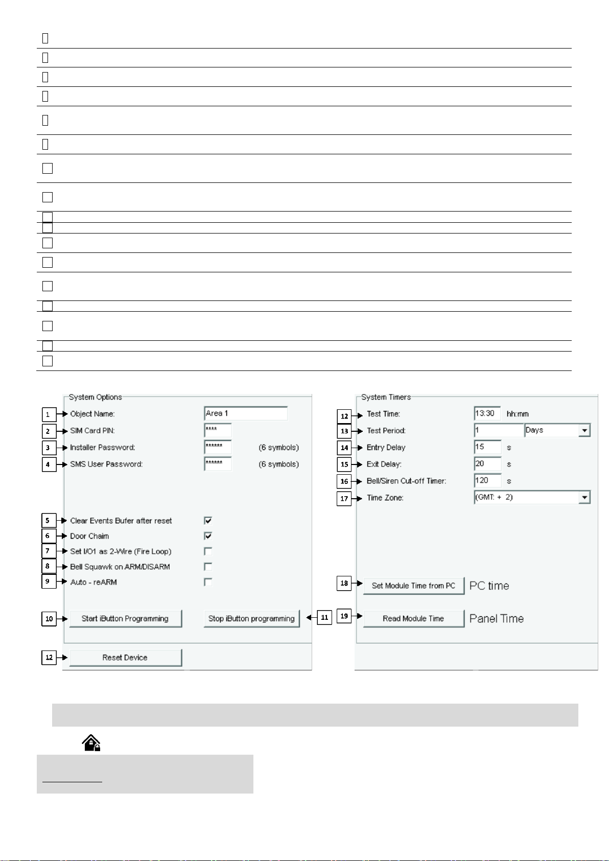
4
SMS User Password
The default SMS User Password is 123456. This code allows you to utilize arming method, as well as
program user codes.
5
Clear Event Buffer After
Reset
When the cell is checked, the memory of unsent reports will be deleted after the module resetting
6
Door Chime
When this box is checked, violations of set Delay zones at the alarm turned off will be accompanied by
keyboard audible (Buzzer) signal
7
Set I/O1 as 2-Wire (Fire
Loop)
When this box is checked, two-wire smoke detectors can be connected to the zone.
8
Bell squawk on ARM/
DISARM
The module can activate the bell output briefly causing the squawk to alert users that the module is being
armed, disarmed or that an Entry or Exit Delay was triggered. Enable or disable the desired option.
9
Auto re-ARM
The module can be programmed to arm the module if there is no activity in the area after the system
disarming.
10
Start iButton
programming
All added iButton keys will be registered in the order of sequence by clicking Start programming
11
STOP iButton
programming
To finish entering the keys, click Stop programming button
12
Test Time
Auto Test report time of day
13
Test Period
Auto Test report period
14
Entry Delay
This delay gives you time to enter the armed premises and enter your code to disarm your system before the
alarm is triggered.
15
Exit Delay
The system will trigger the Exit Delay Timer to provide you with enough time to exit the protected area before
the system is armed.
16
Bell/ Sirel Cut – off
Timer
Duration of audible signal (sirens, Bell) after the alarm system activated. Time shall be written in seconds,
duration from 0 to 9999.
17
Time Zone
18
Set module time from
PC
To set the clock click Set time from PC button and the clock will be set using computer’s clock.
19
Read module time
To read the clock of panel.
12
Reset Device
Reset module command
System Options > System Fault/ Troubles
The System Fault/ Troubles settings let you set the communication
options if the trouble occurs and let you set system voltage loss and
restore options.
Figure 30 The example of System Options > General system Options window.
4.4. System Fault/ Troubles Programming
Page 25
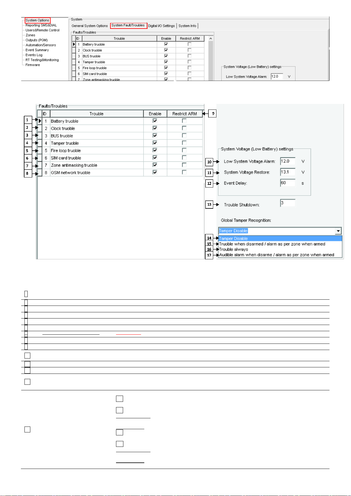
Figure 31 How to find System Options > System Fault/ Troubles window.
1
System voltage trouble
Low system voltage. Power supply or backup battery voltage is low, needs to be recharged, or
replaced.
2
Clock trouble
The time and date has not been set.
3
BUS trouble
The expansion device is no longer communicating with the module.
4
Tamper trouble
The zone(s) that was tampered
5
Fire loop trouble
The trouble is occurring with your smoke detectors.
6
SIM card trouble
Not available or impossible to read SIM card.
7
Zone ant masking trouble
…………….
8
GSM network trouble
SIM card is not registered with the GSM network provider
9
Restrict ARM
In case of such trouble, the arming activation will be restricted.
10
Low System Voltage Alarm
The module has detected a low voltage. This means that your system is running on the backup
battery and voltage is dropped below allowed value.
11
System Voltage Restore
The module has detected that the system voltage has been restored.
12
Event Delay
System low voltage trouble event report delay.
13
Trouble Shutdown
Setting of the allowable number of the same trouble event, where in case of excess of such number
the trouble reporting will be off. The number of such events is counted until the arming mode is
changed (On/Off).
14
Global Tamper Recognition
How the control panel will operate after tamper recognition
14 Tamper Disable
The module will not generate an alarm or trouble.
15 Trouble when disarmed / alarm as per zone when armed
When disarmed: Generates Trouble Only
The module transmits the defined report code.
When armed: Follows Zone Alarm Type
16 Trouble always
Generates Trouble Only (when armed or disarmed)
17 Audible alarm when disarmed / alarm as per zone when armed
When disarmed: Generates Audible Alarm
The module transmits the defined report code and generates an audible alarm.
When armed: Follows Zone Alarm Type
The module follows the zone’s alarm type.
Figure 32 The example of System Options > System Fault/ Troubles window
Table 8 Explanation of every field in "System Fault/Troubles" window
Page 26
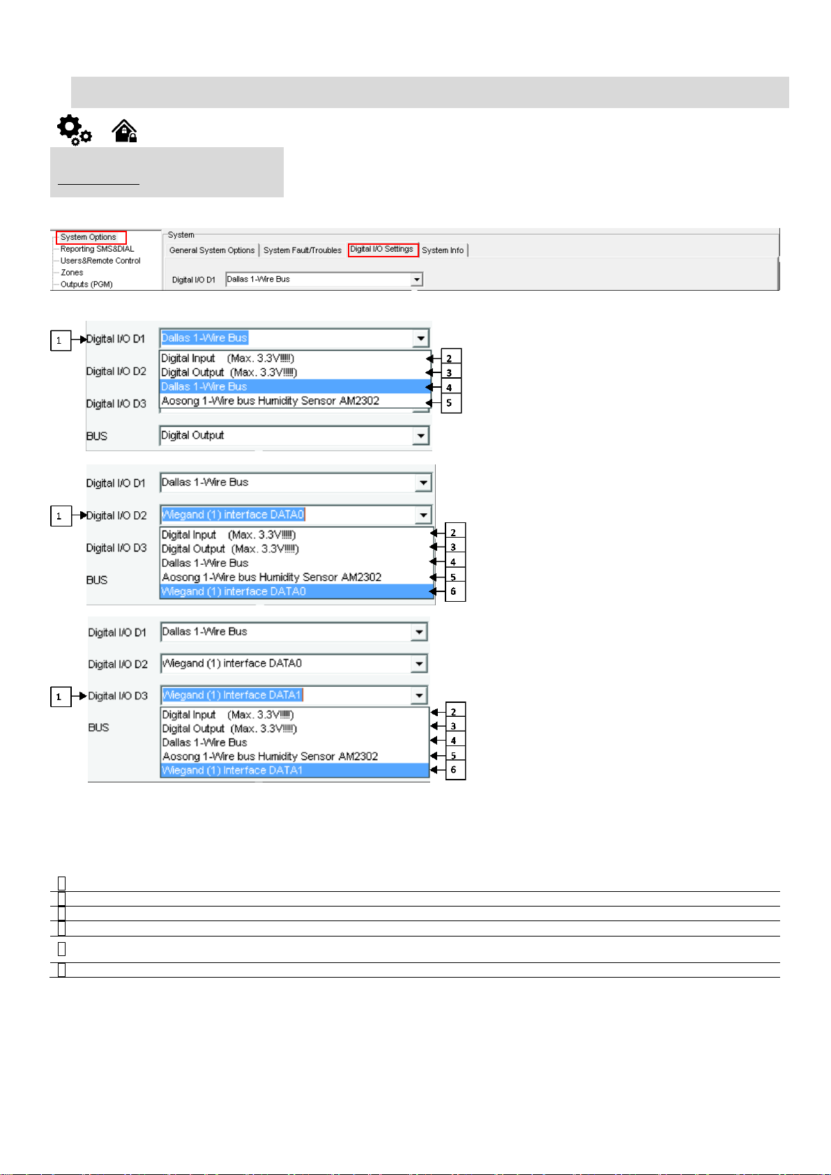
The module can send a system voltage alarm and restore events. It is possible to enable or disable the zone tamper tracking and to set how the module
System Options > Digital I/O Settings
The Digital I/O Settings let you set digital input/ output parameters and expansion
BUS options
1
Digital I/O D1, D2 or D3
Digital I/O D1, D2 or D3 optional settings
2
2 Digital Input (Max 3.3V)
Digital Input (Max 3.3V) assigned to Digital I/O D1, D2 or D3
3
3 Digital Output (Max 3.3V)
Digital Output (Max 3.3V) assigned to Digital I/O D1, D2 or D3
4
4 Dallas 1-Wire Bus
Dallas 1-Wire Bus assigned to Digital I/O D1, D2, D3
5
5 Aosong 1- Wire bus Humidity
Sensor AM2302
Aosong 1-Wire bus. Humidity Sensor AM2302, DHT22, AM2305, AM2306 assigned to
Digital I/O D1, D2 or D3
6
6 Wiegand (1) interface DATA0
Wiegand (1) interface DATA0 assigned to Digital I/O D1, D2 or D3
will operate after tamper recognition.
4.5. Digital Inputs/ Outputs programming
Figure 33 How to find System Options > Digital I/O Settings.
Figure 34 The example of System Options > Digital I/O Settings window
It is possible to select optional digital inputs or outputs, Dallas 1-wire bus, humidity sensors, Wiegand interface or expansion module functions.
Table 9 Explanation of every field in "Digital I/O Settings" window
Page 27
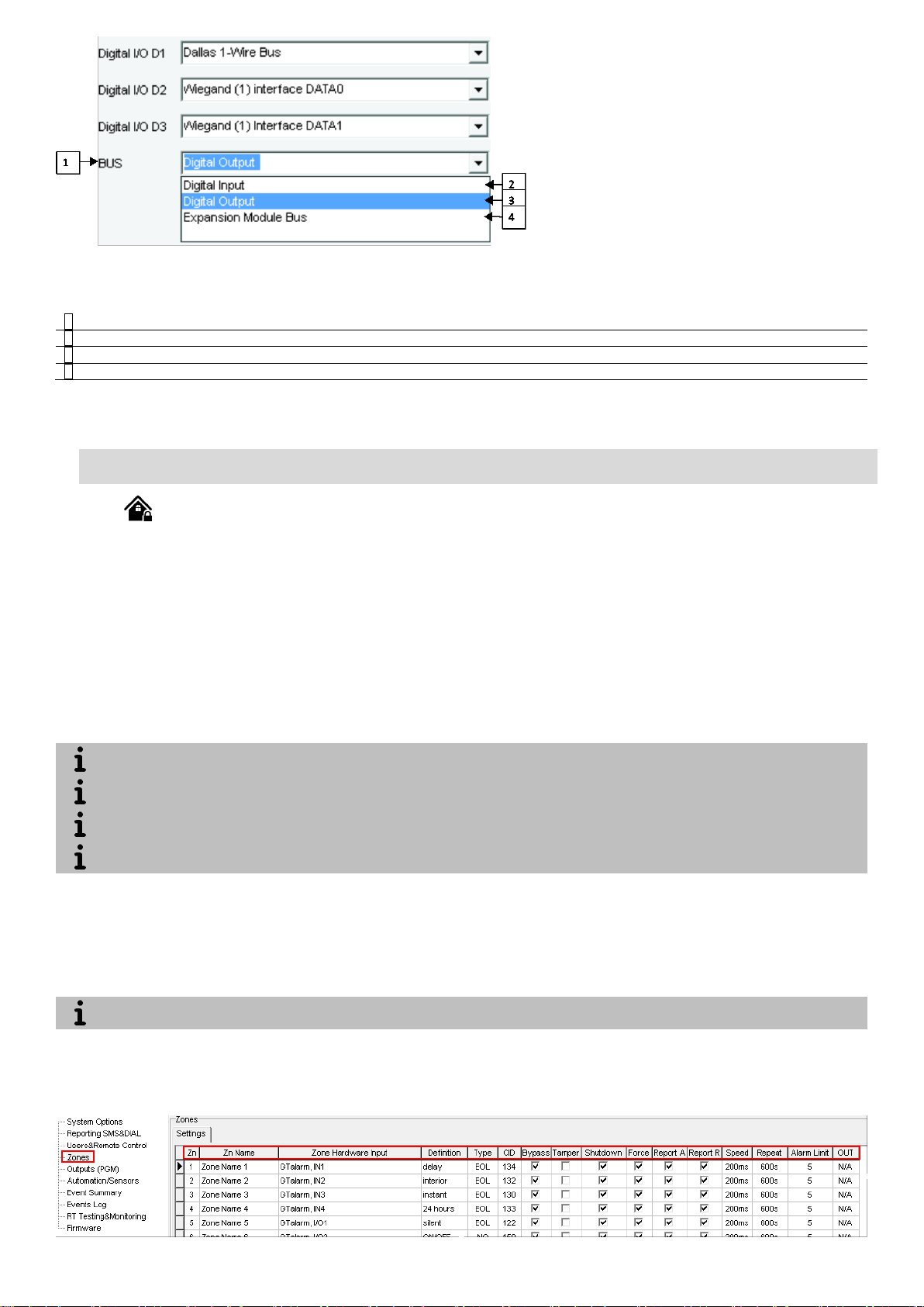
1
BUS
2
Digital Input
Digital Input assigned to BUS
3
Digital Output
Digital Output assigned to BUS
4
Expansion Module Bus
Digital bus for expansion modules
The difference between stay and sleep zone types: “stay” zone type has delay zone timeout, in “sleep” zone type delay zone becomes
instant
The system will NOT activate siren and keypad buzzer only when Instant, Silent zone types is violated.
Any Delay type zone will operate as Instant type zone when the system is armed in the Stay mode. When the system is fully armed, the
Delay type zone will operate normally.
If the zone is not used, it must be disabled.
The system will NOT cause any tamper alarm regarding the physical tamper violation if the associated zone is disabled.
Figure 35 The example of System Options > Digital I/O Settings window
Table 10 Explanation of every field in "Digital I/O Settings" window
4.6. Zones programming
Detection devices such as motion detectors and door contacts are connected to the module’s zone terminals. Once connected, the associated
zone’s parameters must be configured.
GTalarm2 comes equipped with 4 on-board wired zones and 2 programmable I/O inputs. For additional detection device connection, the
number of zones can be expanded. GTalarm2 zones can be expanded with expansion module up to 32.
Zone bypassing allows the user to deactivate a violated zone and arm the system without restoring the zone. If a bypassed zone is violated
or restored during exit/entry delay, or when then system is armed, it will be ignored.
Stay mode allows the user to arm and disarm the alarm system without leaving the secured area. If the zones with Stay attribute enabled are
violated when the system is STAY-armed, no alarm will be caused. Typically, this feature is used when arming the system at home before going to
bed.
The system can be STAY-armed under the following conditions: If a Delay-type zone is NOT violated during exit delay and a zone (-s) with
Stay attribute enabled exists, the system will arm in Stay mode. When arming the system in Stay mode under this condition, one of the available
arming methods must be used that provide exit delay.
status – armed or disarmed. During the tamper alarm, the system will activate the siren/bell and the keypad buzzer and send the SMS text message
to the listed user phone number. The system will cause tamper alarm under the following conditions: If the enclosure of a detection device, siren/bell,
metal cabinet or keypad is opened, the physical tamper switch will be triggered. If needed to get tamper alarms, the field near “Tamper Enabled”,
should be marked. In that case, all tampers and tamper alarm notification by SMS text message is enabled.
The tamper circuit is a single closed loop such that a break in the loop at any point will cause a tamper alarm regardless of the system
1. Install SERA2 software.
2. Connect the module to the computer via mini USB cable.
3. Go to Zones window in the SERA2 software
Figure 36 How to find Zones (Settings) window
Page 28
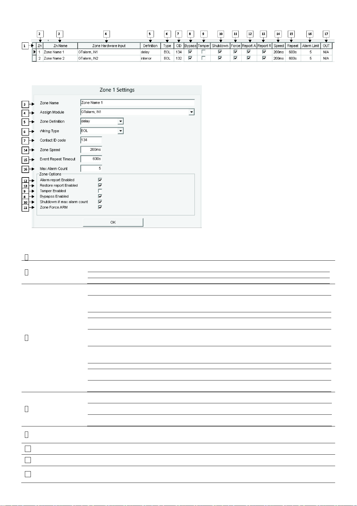
4. Set the required parameters
3
Zone Name
Zone name should be entered.
4
Assign Module
Select the zone hardware input
Zone Disabled
Disables the corresponding zone.
GTalarm, IN1…IN4
The zone hardware input 1… input 4 assigned
GTalarm, I/O1… I/O2
The zone hardware optional Input/ Output 1… Input/ Output 2 assigned
5
Zone Definition
Delay
When armed, provides entry delay when violated. Recommended for door
sensors.
Interior
When armed, instant alarm will sound first if the zone is violated; instant alarm will
follow the entry delay if entry delay is active. Recommended for motion sensor in
front of the door.
Instant
When armed, instant alarm when violated.
24 hours
Instant alarm when violated, audible alarm at default not depending from ARM,
DISARM modes. Recommended for safes, storehouses, tampers.
Silent
Always active, not depending from ARM, DISARM modes. The sms will be send,
but the siren will not be activated. Recommended for voltage, temperature control,
AC mains failure control and for alarm of silent panic.
Fire
Instant alarm and communication when violated not depending from ARM,
DISARM modes. Siren signal with interruptions will be generated. Recommended
for smoke, fire detectors.
ON/OFF
Interior STAY
Similar to ‘Instant’ except the module will auto bypass the zone if Armed in the
Stay mode
Instant STAY
Similar to ‘Instant’ except the module will auto -bypass the zone if Armed in the
Stay mode
6
Wiring Type
EOL
End of line resistor. Input type with resistor.
NC
Normal Close. The alarm will be send when the circuit between input and ground (V) will be broken.
NO
Normal Open. The alarm will be send when the input will be connected with ground
(-V)
7
Contact ID
code
The module supports Contact ID reporting.
If any other data is programmed the module will automatically generate the reporting event when transmitting to
the central station.
14
Zone Speed
The Input Speed defines how quickly the module responds to an open zone detected on any hardwired input
terminal (does not apply to addressable motion detectors and door contacts).
15
Event Repeat
Timeout
Insensitive time to recurrent zone events
16
Max Alarm
Count
When the particular number of zone events set has occurred, the other events of the same zone will not be
responded for the time set in Event Repeat Timeout. After this time expired (or when disarmed), a new count of the
number of zone events will be started.
5. Write configuration by pressing „Write“ icon
Figure 37 the example of Zones (Settings) window
Figure 38 the example of Double click on the required zone window
Table 11 Explanation of every field in "Zones" window
Page 29
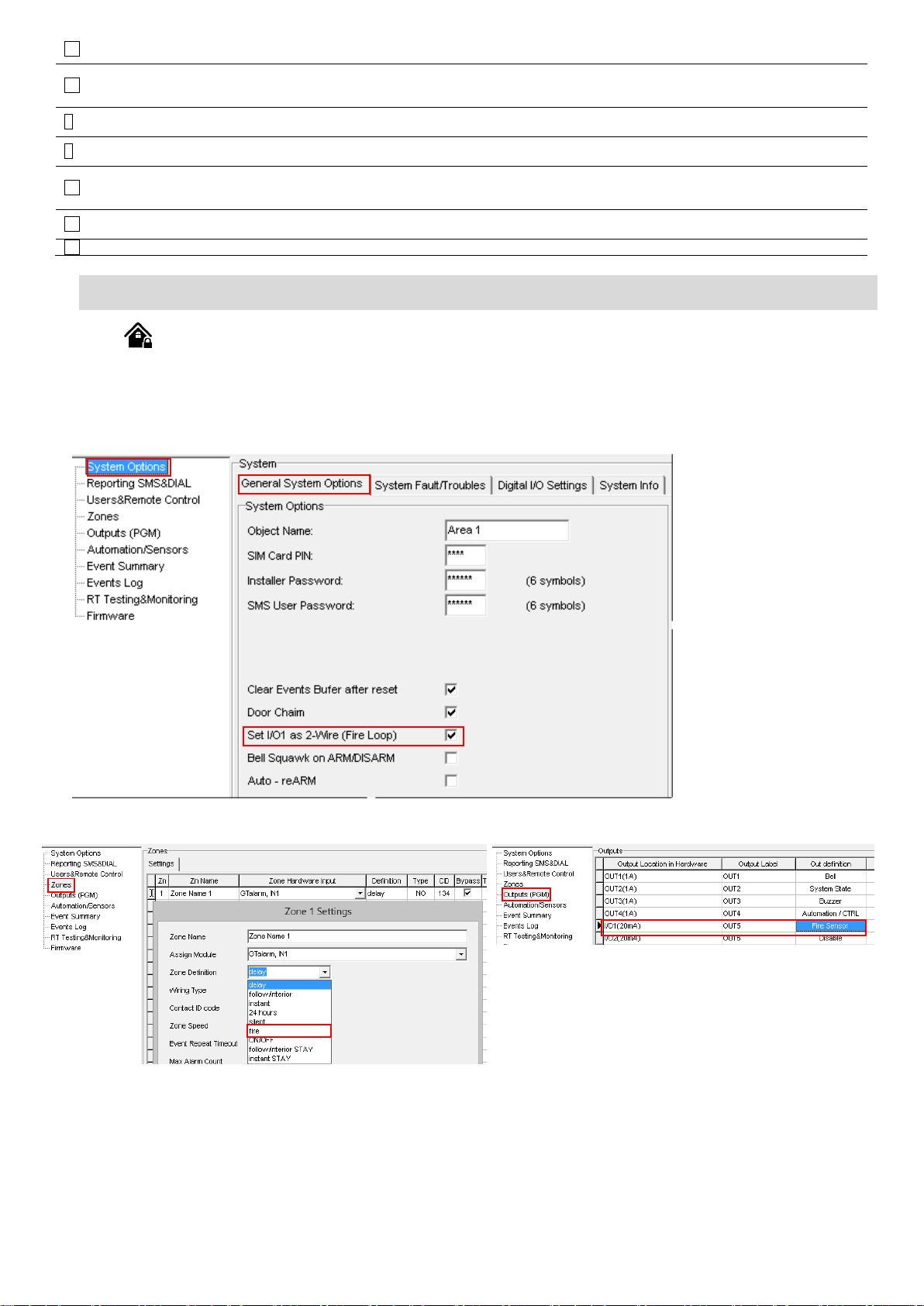
12
Alarm Report
Enabled
The system will report alarm event and log it to the event buffer
13
Restore
Report
Enabled
The system will report restore event and log it to the event buffer
9
Tamper
Enabled
The system will detect a tamper condition with one or more sensors on the system
6
Bypass
Enabled
The system will allow zones to be Manually Bypassed.
10
Shutdown if
max alarm
count
The system will stop generating alarms once the max alarm count Limit is reached. It resets every time the
partition that is assigned to the corresponding zone is armed.
11
Zone Force
ARM
Only force zones can be bypassed when the module is Force armed. Fire Zones cannot be Force Zones.
17
OUT
determines which output will be activated
4.7. 2-wire smoke detectors programming
Figure 39 How to find System Options>General System Options window
1. In the Zone table set I/O1 definition to “Fire”
Figure 40 How to find Zones window
1. In the output table I/O1(20mA) set to “Fire Sensor”
Figure 41 How to find Outputs (PGM) window
2. Write configuration by pressing “Write” icon.
or the smoke detector activates, whether the system is armed or disarmed, the control panel will generate an alarm. If the line is open, the “Zone
Fault” report code is sent to the monitoring station or to the user, if programmed.
The parameters of the zone should be defined as a “Fire Zone”. I/O1 can be defined as a 2-wire smoke detector input if a line short occurs
6. Install SERA2 software.
7. Go to “System Options> General System Options” from the menu and mark “Set I/O as 2-Wire (Fire Loop).
Page 30
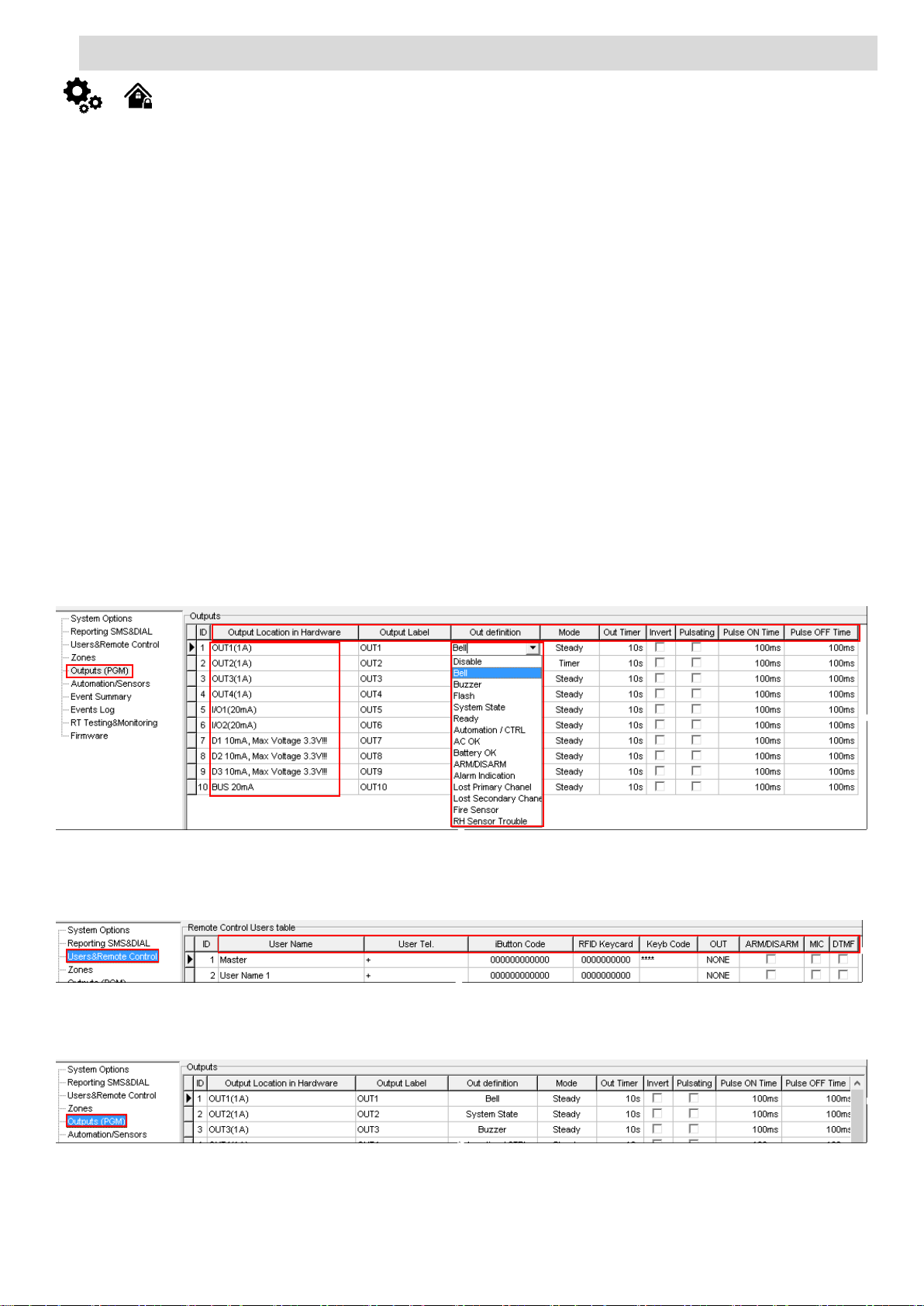
4.8. Outputs. Bell & PGM programming
A PGM output is a programmable output that toggles to its set up state when a specific event has occurred in the system. Normally, PGM
outputs can be used to open/ close garage doors, activate lights, heating, watering and much more. When a PGM output turns ON, the system triggers
any device or relay connected to it.
GTalarm2 comes equipped with four open-collector PGM outputs allowing to connect up to four devices or relays. Also GTalarm2 comes with
two programmable 20mA outputs, three 10 mA and max voltage 3.3V outputs, and with one 20mA programmable output expansion module BUS.
Each PGM output has a name that can be customized by the user. Typically, the name specifies a device type connected to a determined
PGM output, for Example: Lights.
If the output is not in used, it should be disabled. Once a PGM output is disabled, it can no longer be turned ON or OFF unless it is enabled
again. It is possible to instantly turn ON an individual PGM output for a determined time period and automatically turn it OFF when the time period
expires. When the PGM output is turned ON or OFF, the system will send a confirmation by SMS text message to the user phone number that the
SMS text message was sent from.
The automatic action of the determined PGM output can be set as follows:
Turn ON – Determines whether the PGM output is to be turned ON.
Turn OFF – Determines whether the PGM output is to be turned OFF.
Pulse – Determines whether the PGM output is to be turned ON or OFF for a set period of time in seconds based on the PGM output startup
state set up.
The aforementioned PGM output action can be automatically carried out under the following events that have occurred in the system:
System armed or disarmed.
Alarm begins or stops
Temperature falls – Temperature falls below the set MIN value of a determined temperature sensor.
Temperature rises – Temperature rises above the set MAX value of a determined temperature sensor.
Zone violated – A determined zone is violated.
Zone restored – A determined zone ranging is restored.
The user can also set a custom text, which will be sent by SMS text message to user phone number when the automatic PGM output action
is carried out.
1. Install SERA2 software.
2. Connect the module to the computer via mini USB cable.
3. Go to Outputs (PGM) window in the SERA2 software
4. Parameters of the selected output should be set:
5. output operation description (OUT definition): disable, bell, buzzer, flash, system state, ready, automation/ CTRL, AC OK, battery OK, ARM/
DISARM, alarm indication, lost primary channel, lost secondary channel, fire sensor, RH sensor trouble.
6. State type: flash, timer, steady mode.
7. If necessary output operation might be inverted.
8. Write configuration by pressing write icon
Figure 42 How to find Outputs (PGM) window
9. If you need to control outputs by short call or sms, go to “Users & Remote Control” window and enter telephone numbers of users, who will
be able to control selected outputs via free short call.
10. Write configuration by pressing write icon
Figure 43 How to find Users & Remote Control window
In order to control big power alternating current equipment, it is comfortable to use solid state relays.
Standard AC/DC adapter with the voltage 10V-14V and current >=1A might be used to powering the module.
Figure 44 How to find required Outputs window.
Page 31
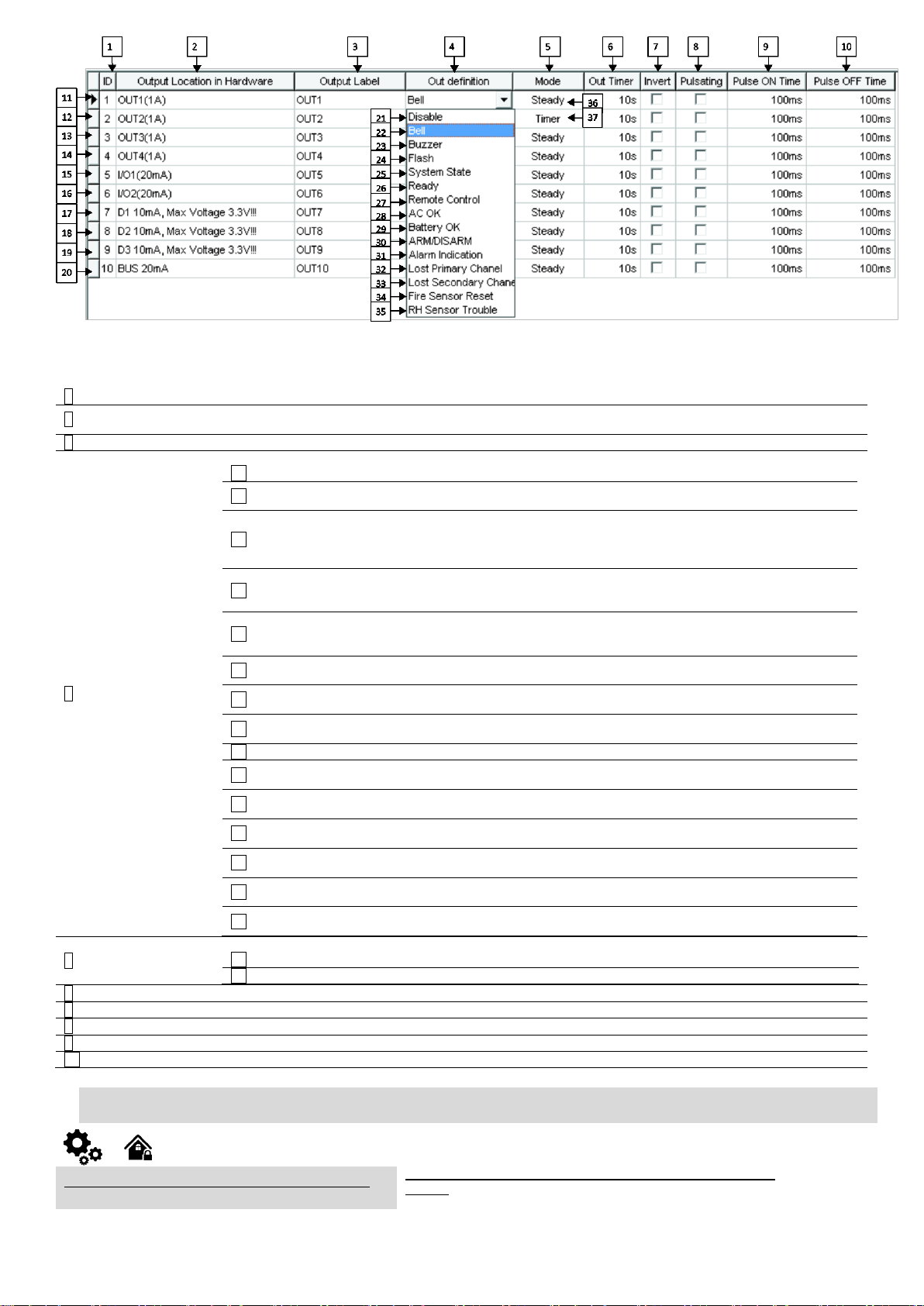
Figure 45 The example of Outputs window
1
ID
Output sequence number.
2
Output Location
in Hardware
The outputs hardware location.
3
Output Label
Output name
4
Out definition
Selection of output operation mode.
21 Disable
Output disabled
22 Bell
Output for connection of audible sounder (siren). After the alarm system
actuation a continuous or pulse (fire) signal is generated.
23 Buzzer
Output for buzzer connection. After the alarm system activated a pulse signal is
generated within Exit Delay time, and continuous signal - within Entry Delay time
or when the alarm system is disturbed. When the alarm system is turned off,
operates like keyboard buzzer.
24 Flash
Output for connection of light indicator. When the alarm system is on, a
continuous signals generated, and if the alarm system is disturbed - pulse
signal. Signal is terminated by turning off the alarm system.
25 System State
Output for connection of light indicator of the alarm system status. Within Exit
Delay time a pulse signal is generated, and when the alarm system activated –
continuous. Signal is terminated by turning off the alarm system.
26 Ready
Output for connection of light indicator of input statuses. If all zones are clear
(none violated), a continuous signal is generated.
27 Remote Control
Remote control by call mode is enabled. Output designed for connection of
electrical devices which will be controlled by SMS message or phone call
28 AC OK
Output for connection of indicator about control panel supply from alternating
current.
29 Battery OK
Output for connection of indicator about control panel supply from battery.
30 ARM/ DISARM
Output for connection of light indicator of the alarm system status. When the
alarm system is on a continuous signal is generated.
31 Alarm Indication
Output for connection of light indicator showing alarm status of the alarm
system. After the alarm system actuation a continuous signal is generated.
32 Lost Primary channel
Output where a continuous signal is generated when communication with
primary channel was lost.
33 Lost secondary channel
Output where a continuous signal is generated when communication with
secondary channel was lost.
34 Fire Sensor Reset
Output for reset of fire sensor operation. Its status changes 5 sec. and returns to
the initial one.
35 RH Sensor Trouble
Output for RH Sensor trouble operation. In this mode output can automatically
reset Humidity sensor if trouble occurs.
5
Mode
Output control mode.
36 Steady
Steady ON/OFF mode
37 Timer
Output ON pulse mode
6
Out Timer
Pulse time duration can be from 1 to 999999 sec.
7
Invert
Inversion is activated
8
Pulsating
Pulsating mode is activated. Then output is activated it will pulsate according pulse ON/OFF time.
9
Pulse ON Time
Pulsating mode pulse ON duration.
10
Pulse OFF Time
Pulsating mode pulse OFF duration.
Users & Remote Control > Remote Control Users Table
The Remote Control Users Table window let you set remote control
options.
Table 12 Explanation of every field in "Outputs" window
4.9. Users & Remote Control programming details.
The system supports up to 800 user phone numbers for remote control purpose. When the phone number is set, the user will be able to
arm/disarm the system and control outputs by SMS text messages and free of charge phone calls as well as to configure the system by SMS text
messages. By default, the system accepts incoming calls and SMS text messages from any phone number. Once a user phone number is listed, the
Page 32
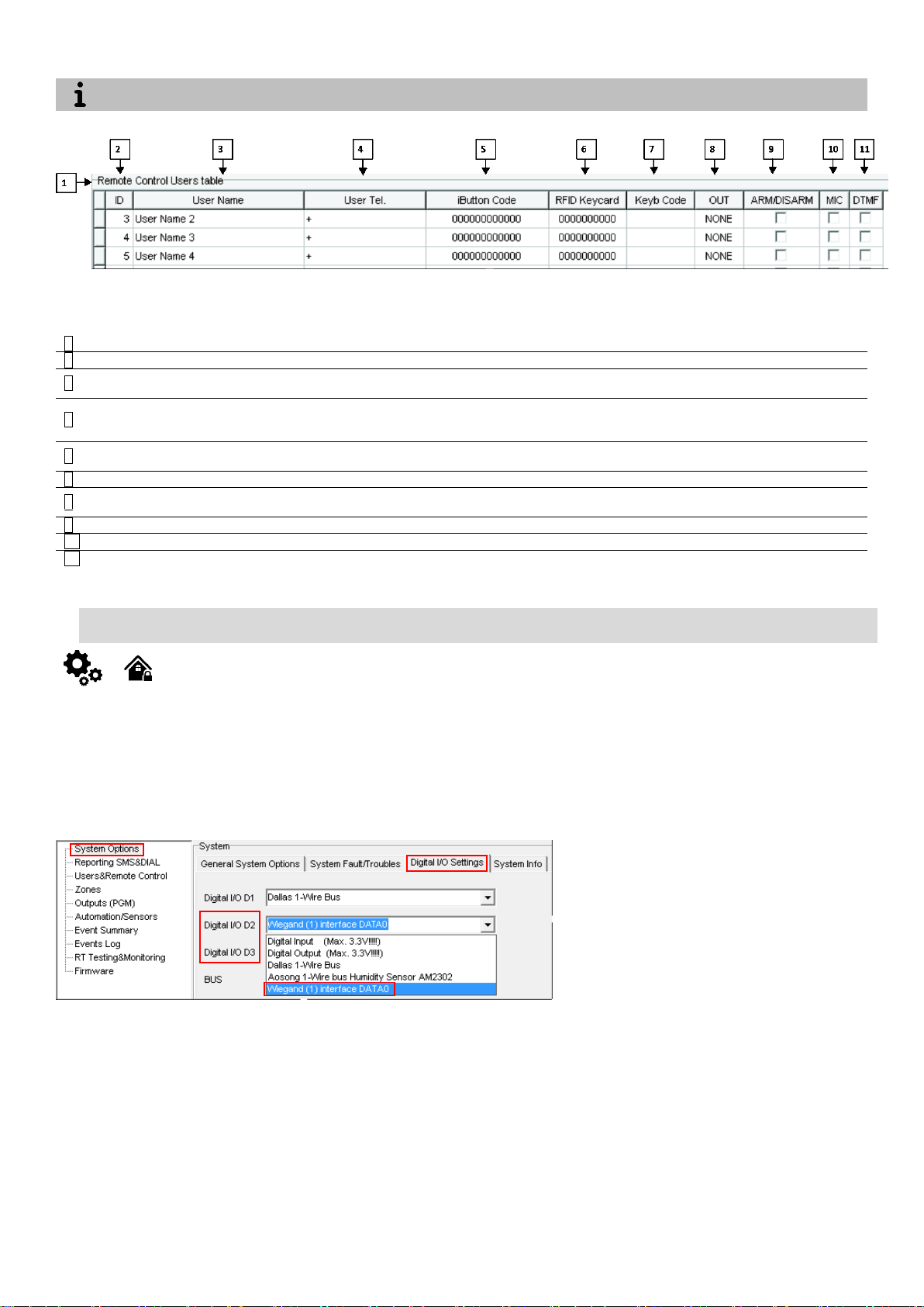
system ignores any incoming calls and SMS text messages from a non-listed phone number as well as it rejects the SMS text messages containing
The module could be controlled only by these users, whose phone numbers entered in the memory of the module
2
ID
3
User Name
The name of users who will be able to control the module should be entered in this column.
4
User Tel.
Telephone numbers of users who will be able to control the module by dialing should be entered in this column.
User number should be entered with international code.
5
iButton Code
iButton Maxim iButton key DS1990A - 64 Bit ID code. Might be entered manually or automatically registered
after the module enters keys association mode. In order to delete the code, it is necessary to enter
000000000000
6
RFID Keycard
RFID Keycard code might be entered manually. In order to delete the code, it is necessary to enter
000000000000
7
Keyb Code
Key button code might be entered manually. In order to delete the code, it is necessary to enter 000000000000
8
OUT
The selected input will be switched, if a user will call from this number. Preferred input may be assigned to each
user’s number. Thus different users are able to control different objects.
9
ARM/DISARM
If this check box is checked, a user will be able to ARM/DISARM the module by dialing.
10
MIC
If this check box is checked, a user will be able to activate microphone and to switch on voice listening.
11
DTMF
The module uses DTMF (touchtone) to control the module.
wrong SMS password even from a listed user phone number.
Figure 46 The example of Users & Remote Control > Remote Control Users Table window
Table 13 Explanation of every field in "Users & Remote Control" window
4.10. Wiegand Keypad & RFID card reader programming
Install SERA2 software.
Connect the module to the computer via mini USB cable.
„Go to System options“> Digital I/O Settings
Set Digital I/O D2 to Wiegand interface Data0
Set Digital I/O D3 to Wiegand interface Data1
Go to “Users and Remote control” window and enter RFID keycard codes. The first code is activated automatically, all other codes
you have to enter. Or press [Start iButton/RFID programming mode] button on System settings window.
Write configuration
Figure 47 How to find System Options> Digital I/O Settings window
Page 33
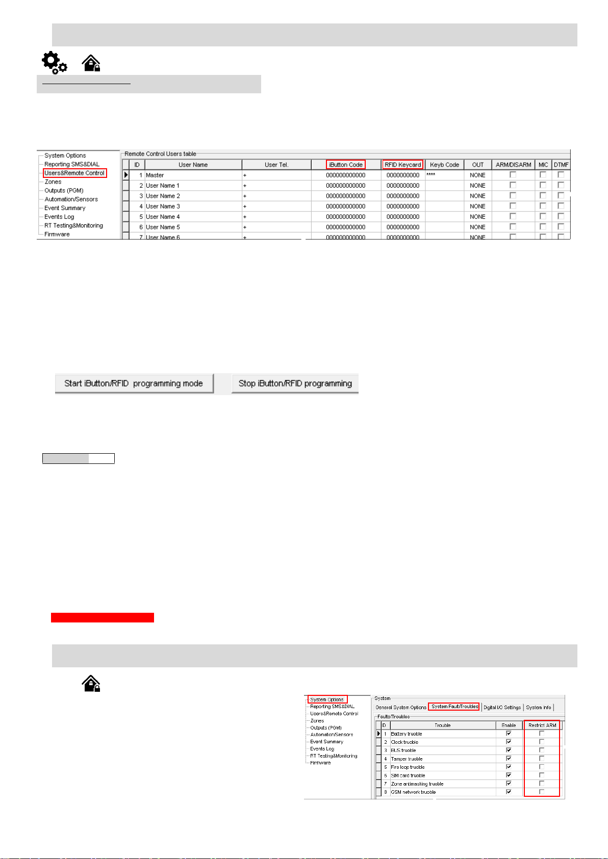
4.11. iButton keys & RFID programming
Users & Remote Control > Remote Control Users Table
The Remote Control Users Table window let you set remote control options.
If you need to enter iButton learning/ deleting mode by
sending sms message, you have to send:
INST123456˽063˽S
INST = Install. Configuration of the parameters.
123456= Installer‘s password
˽= Space character
063= command code (iButton keys learning/deleting mode)
˽= Space character
S=iButton keys entering/deletion mode.
0-Disable iButton/RFID keys learning mode,
1-Enable iButton/ RFID keys learning mode,
2-iButton/ RFID keys deleting mode,. Delete these keys
from memory, which will be touched to the reader.
When you receive a message into your mobile phone in relation to activation
of iButton key programming mode, touch the key to the reader and its unique code
will recorded into system memory. Buzzer will notify you about successful
recording by beeping twice. The system allows to associate up to 800 iButton keys
and 800 RFID proximity cards or tags. Each time when touching the key, the
system records its code till all desirable keys will be recorded. If during 2 minutes
not a single iButton key will not be learned, the system will automatically exit keys
learning mode. After finishing programming of the keys, you might send SMS
message.
You can disable recording of new keys into memory. In the event of failure to
send this message, ARM/DISARM of the system via iButton key will not operate.
Control functions for all newly associated keys will be assigned according to
MASTER key. For example: If MASTER key will control Out1, all newly associated
keys will also control Out1.
You can delete all iButton keys from the memory. If you have the key, that
you want to delete from the memory, you have to send sms and touch the key to
the reader. 2 minutes later, the module will deactivate the keys deletion mode.
The system can be armed in one of four modes DISARM, ARM,
SLEEP, STAY.
By default, it is allowed to arm the system while the following system
faults are present:
• Low battery.
• Battery dead or missing.
• Battery failed.
• Date/time not set.
• GSM connection failed.
• GSM/ GPRS antenna failed.
If needed, restrict arm, when such trouble occur, check near such
trouble in the System options> System Fault/Troubles window. And in
case of such trouble, the arming activation will be restricted.
Figure 50 How to find System Options> System Fault/
Troubles window
It is possible to enter manually iButton or RFID Keycard codes. In that case, you have to:
Install SERA2 software
1. Go to “Users& Remote Control” table.
Figure 48 How to find Users/Access Control window
2. Enter iButton or RFID Keycard codes for users.
3. Select iButton or RFID Keycard action OUT/ARM/DISARM, etc.
Write the configuration into the module by pressing “Write” icon
It is possible to enter automatically iButton or RFID Keycard codes.
Association of iButton keys or RFID Keycards is carried out by activating special programming mode - by sending SMS or by pressing „Learn
iButtons/RFID mode“in the SERA2 configuration program.
If you need to enter iButtons learning mode by SERA2 software, you have to:
Install SERA2 software.
3. Go to the “System options> General system options” and press “Start iButton/RFID programming mode” to start entering iButton keys.
4. Press “Stop iButton programming” to stop entering iButton keys.
Figure 49 The example of Start/Stop iButton/RFID programming mode
5. Write configuration by pressing “Write” icon.
Key button entering/Deleting
4.12. DISARM /ARM/SLEEP/STAY the security system
Page 34
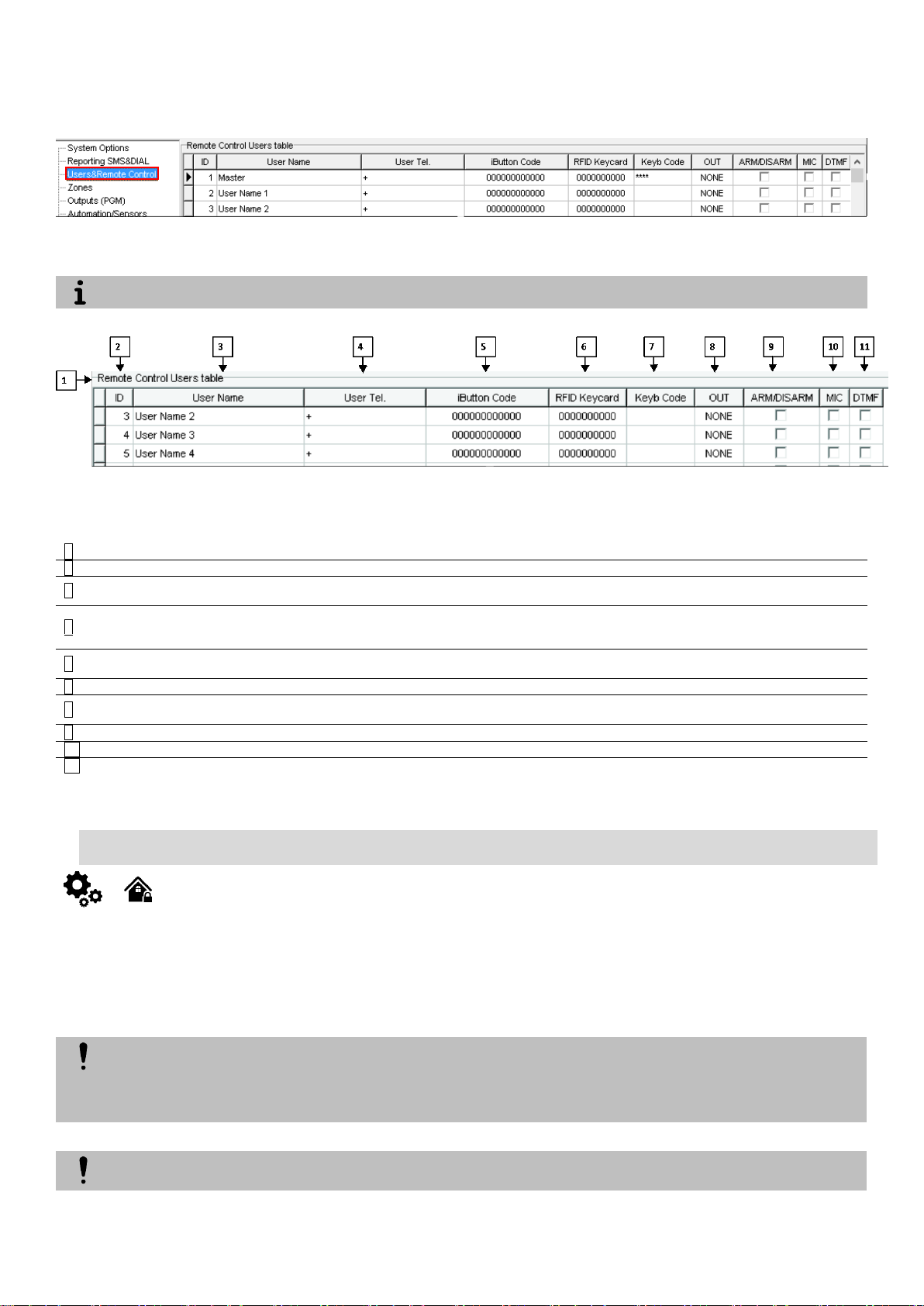
The system supports up to 800 user phone numbers for remote control purpose. When the phone number is set, the user will be able to
The module could be controlled only by these users, whose phone numbers entered in the memory of the module
2
ID
3
User Name
The name of users who will be able to control the module should be entered in this column.
4
User Tel.
Telephone numbers of users who will be able to control the module by dialing should be entered in this column.
User number should be entered with international code.
5
iButton Code
iButton Maxim iButton key DS1990A - 64 Bit ID code. Might be entered manually or automatically registered
after the module enters keys association mode. In order to delete the code, it is necessary to enter
000000000000
6
RFID Keycard
RFID Keycard code might be entered manually. In order to delete the code, it is necessary to enter
000000000000
7
Keyb Code
Key button code might be entered manually. In order to delete the code, it is necessary to enter 000000000000
8
OUT
The selected input will be switched, if a user will call from this number. Preferred input may be assigned to each
user’s number. Thus different users are able to control different objects.
9
ARM/DISARM
If this check box is checked, a user will be able to ARM/DISARM the module by dialing.
10
MIC
If this check box is checked, a user will be able to activate microphone and to switch on voice listening.
11
DTMF
The module uses DTMF (touchtone) to control the module.
The system will NOT transmit any data to monitoring station while configuring the system remotely via GPRS network. However, during
the remote connection session, the data messages are queued up and transmitted to the monitoring station after the configuration
session is over. SERA2 software provides remote system configuration ability via Internet using TCP/IP server on SERA2 software. The
connection can be established on the system via GPRS network. After the remote system configuration is complete the session will
automatically expire in 20 minutes. Alternatively, the connection with the server can be terminated at any time by sending an SMS text
message. Terminate the connection with server SMS SMS text message content: ….
NEVER add a phone number of the device’s SIM card as a user phone number!
arm/disarm the system and control outputs by SMS text messages and free of charge phone calls as well as to configure the system by SMS text
messages. By default, the system accepts incoming calls and SMS text messages from any phone number. Once a user phone number is listed, the
system ignores any incoming calls and SMS text messages from a non-listed phone number as well as it rejects the SMS text messages containing
wrong SMS password even from a listed user phone number.
Figure 51 How to find Users & Remote Control window
Figure 52 the example of Users & Remote Control > Remote Control Users Table window
Table 14 Explanation of every field in "Users & Remote Control" window
4.1. Reporting SMS&Dial in Case of Alarm Events
connection and SMS text messages from the system. When the system is armed or disarmed by free of charge phone call or SMS text message, the
system sends a confirmation by SMS text message to user phone number that the system arming/disarming.
number as well as it rejects the SMS text messages containing wrong SMS password even from a listed user phone number. To permit/deny system
arming/disarming by phone call and SMS text message that contain a valid SMS password, configuration by SMS text message that contain a valid
SMS password from any phone number, please refer to the following configuration methods.
The system supports up to 8 user phone numbers identified as User 1 through 8 for monitoring purpose: receive alarm phone calls via GSM
By default, once a user phone number is listed, the system ignores any incoming calls and SMS text messages from a non-listed phone
Page 35
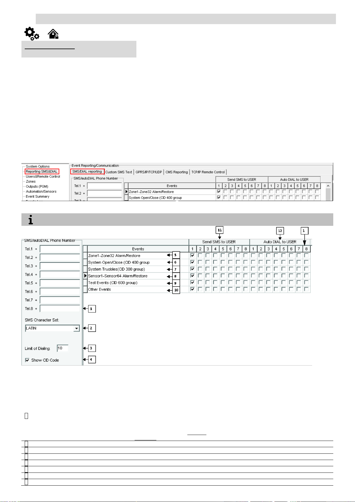
4.1.1. Reporting to the user‘s mobile phone
Reporting SMS & DIAL > SMS DIAL Reporting
The SMS DIAL Reporting settings let you enter user’s phone numbers and set
events that will be reported to the user
The module could be controlled and monitored only by these users, whose phone numbers entered in the memory of the module
1
The SMS/auto DIAL Phone Numbers
The SMS/auto DIAL Phone Numbers whom SMS messages will be send and calls will be
made should be entered. User number up to 8. User numbers should be entered with
international code. Near the telephone number of each user, check boxes which events will
be sent to that user. User must type mobile number in the international format (it consist of
only those digits that overseas callers must type:
[country code][area code][local number]) Without symbol ‘+’.
E.g. the mobile number of user in United Kingdom is
+44 (0) 113 xxx xxxx, so Correctly entered user number: 44113xxxxxxx
Incorrectly entered user number: 440113xxxxxxx or 0113xxxxxxx
2
SMS Character Set
SMS character set selection.
3
Limit of Dialing
Indicate maximum number of unsuccessful calls
4
Show CID Code
Report Contact ID code
5
Zone1- Zone32 Alarm/ Restore
Zone1- Zone32 alarm and restore events reporting is enabled.
6
System Open/ Close (CID 400 group)
System ARM/DISARM/STAY reporting is enabled.
7
System Troubles (CID 300 group)
System trouble reporting is enabled.
8
Sensor1- Sensor32 Alarm/ Restore
Sensor 1 – Sensor32 alarm and restore events reporting is enabled.
When a zone or tamper is violated, depending on zone, the system will cause an alarm. During the alarm, the system will follow this pattern:
1. The system activates the siren/bell. The siren/bell will emit pulsating sound if the violated zone is of Fire type, otherwise the sound will be steady.
2. The system attempts to send an SMS text message (if programmed), containing the violated name. The system will send SMS text messages
regarding each violated zone separately.
a) If the user phone number is unavailable, it will attempt to send the SMS text message to the next listed user phone number, assigned to the same
zone as the previous one. The user phone number may be unavailable due to the following reasons: mobile phone was switched off or was out of
GSM signal coverage.
b) By default, the system will continue sending the SMS text message to the next listed user phone numbers in the priority order. The system try to
send the SMS text message as many times as programmed.
3. If programmed, the system attempts to ring the first user phone number via GSM. The system will dial regarding each violated zone separately.
The system will dial the next listed user phone number, assigned to the same zone. The user can be unavailable due to the following reasons:
Mobile phone was switched off, mobile phone was out of GSM signal coverage or provided “busy” signal.
d) The system will continue dialing the next listed user phone numbers in the priority order. The system will dial again as many times as programmed
and the same order as phone numbers listed in the memory if it end up with all unsuccessful attempts to dial to the user.
Figure 53 How to find required Reporting SMS & DIAL > SMS DIAL Reporting window.
Figure 54 The example of Reporting SMS & DIAL > SMS DIAL Reporting window
Table 15 Explanation of every field in "SMS DIAL Reporting" window
Page 36
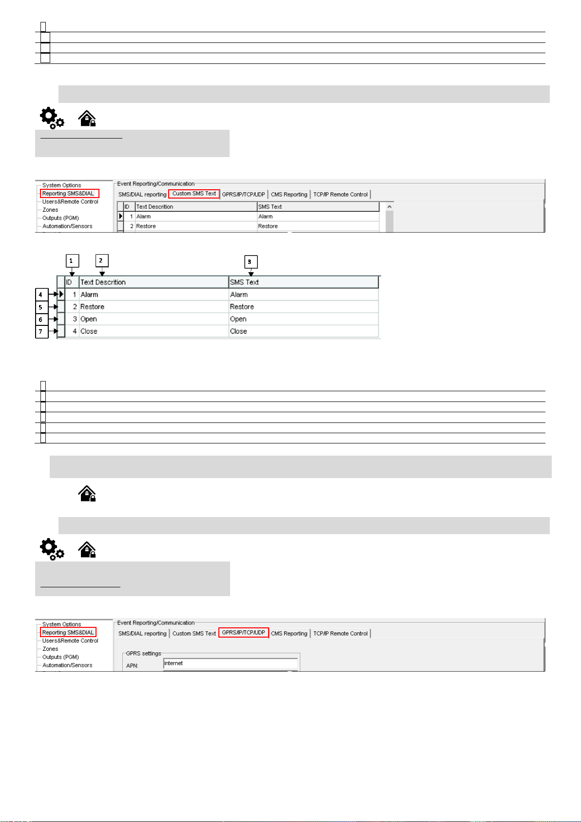
9
Test Events (CID 600 group)
Communication test reporting is enabled.
10
Other Events
Other events reporting is enabled.
11
Send SMS to USER
SMS reporting to selected index of telephone number is enabled.
12
Auto DIAL to USER
Auto DIAL to selected index of telephone number is enabled.
Reporting SMS & DIAL > Custom SMS Text
The Custom SMS Text options let you enter the text that will be send to the user in case
if the alarm event occur.
2
Text Description
Event type text
3
SMS Text
Text which will be visible in SMS message is entered.
4
Alarm
SMS message text of alarm report can be entered.
5
Restore
SMS message text of restore report can be entered.
6
Open
SMS message text of open report can be entered.
7
Close
SMS message text of close report can be entered.
Reporting SMS & DIAL > GPRS/ IP/ TCP/ UDP
The GPRS/ IP/ TCP/ UDP window let you set GPRS, IP, TCP and UDP parameters
4.1.2. Custom SMS Text
Figure 55 How to find required Reporting SMS & DIAL > Custom SMS Text window.
Figure 56 the example of Reporting SMS & DIAL > Custom SMS Text window
Table 16 Explanation of every field in "General System Options" window
4.2. Reporting to the Central Monitoring Station
4.2.1. GPRS/ IP/ TCP/ UDP details programming
Figure 57 How to find required Reporting SMS & DIAL > GPRS/ IP/ TCP/ UDP window.
Page 37
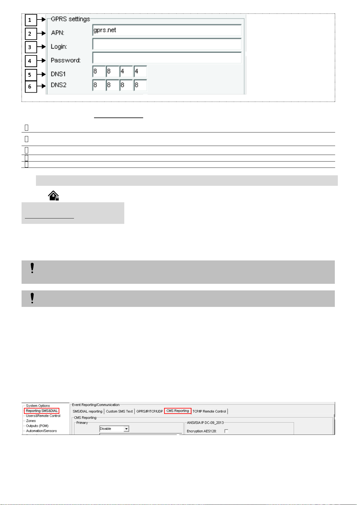
Figure 58 The example of Reporting SMS & DIAL > GPRS/ IP/ TCP/ UDP window
3
APN
Name of GSM operator network where SIM card inserted in the module is operating.
4
Login
User name of GSM operator network where SIM card inserted in the module is operating (if required by network
operator).
5
Password
User password of GSM operator network where SIM card inserted in the module is operating.
6
DNS1
IP addresses of 1st DNS server.
7
DNS2
IP addresses of 2nd DNS server.
Reporting SMS & DIAL > CMS Reporting
The CMS Reporting window let you set reporting to central monitoring station parameters
The module will NOT send any data to the monitoring station while remote connection, remote firmware update is in progress. However,
during the remote connection session process, the data messages will be queued up and transmitted to the monitoring station after the
remote connection session is over, while during the remote firmware update process NO data will be queued up and all data messages
will be lost.
Phone calls via GSM network to the listed user phone number in case of alarm are disabled by force when MS mode is enabled.
Table 5 explains every field in the Reporting SMS & DIAL > GPRS/ IP/ TCP/ UDP window
4.2.2. Central Monitoring Station details programming
connects to the central monitoring station when the CMS (Central Monitoring Station) mode is enabled, set to GPRS.
based on the communication method a constant and stable connection with the monitoring station must be ensured. In case of connection failure, the
system will attempt to restore the connection and if the monitoring is unavailable for a lengthy period of time, the system switch to backup CMS.
Data Messages – Events
The system supports the following communication methods and protocols:
GPRS network –SIA IP protocol (ANSI/SIA DC-09-2012; configurable as encrypted and non-encrypted).
SMS –SMS to User text format.
Initially, the system communicates via primary connection with the monitoring station. By default, if the initial attempt to transmit data is unsuccessful,
the system will make additional attempts until the data is successfully delivered. If all attempts are unsuccessful, the system will follow this pattern:
If all attempts by all set connections are unsuccessful, the system will wait until the delay time (by default – 1200 seconds) expires and will attempt to
transmit data to the monitoring station again starting with the primary connection.
The system can be configured to report events to the monitoring station by transmitting data messages to the monitoring station. The system
When using the CMS mode, the data messages transmitted to the monitoring station will gain the highest priority for the delivery, therefore
1. The system switches to the backup connection that follows in the sequence (presumably - Backup 1).
2. The system then attempts to transmit data by the backup connection.
3. If the initial attempt is unsuccessful, the system will make additional attempts until the data is successfully delivered.
4. The system ends up with all unsuccessful attempts.
Figure 59 How to find required Reporting SMS & DIAL > CMS Reporting window
Page 38
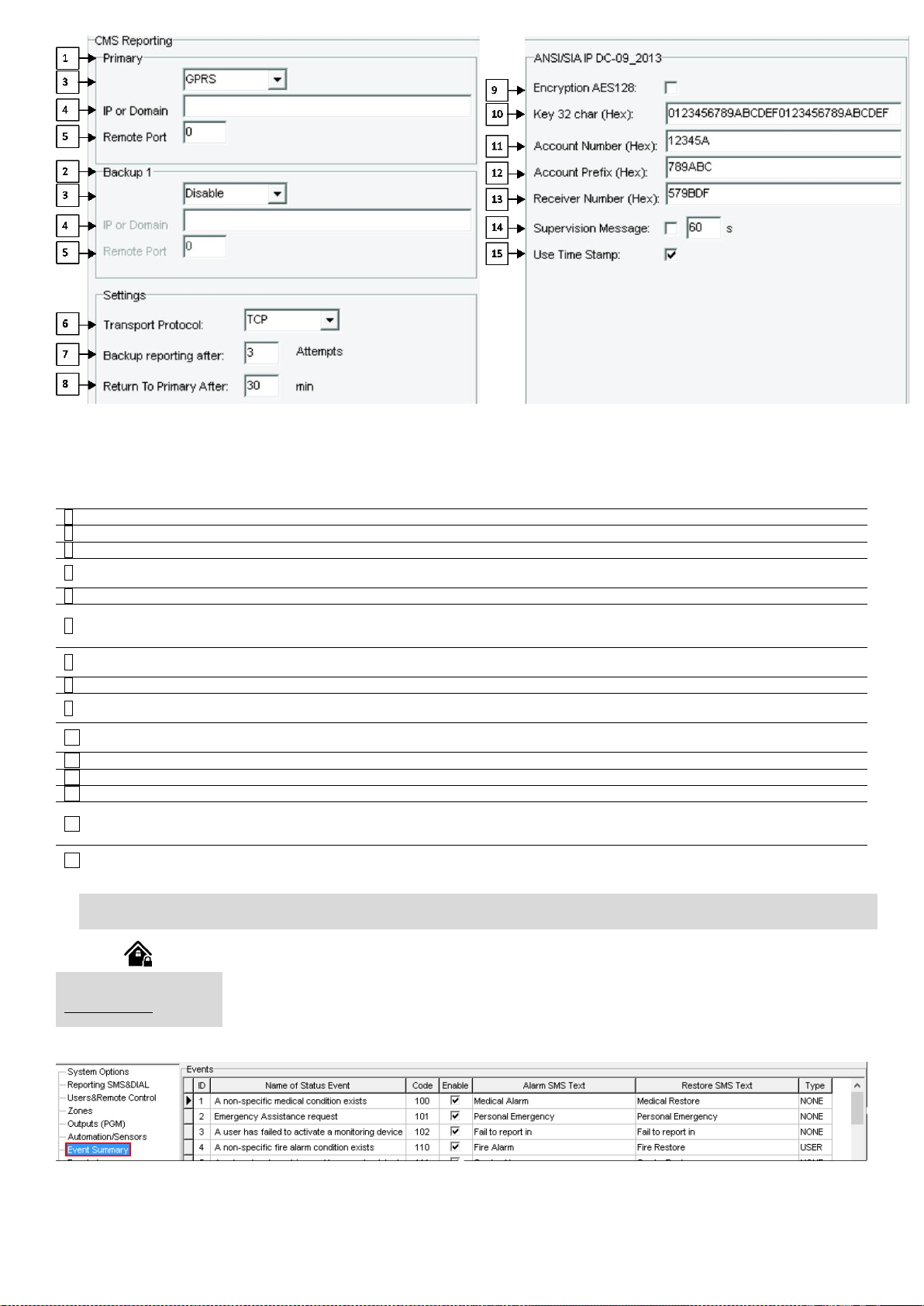
Figure 60 the example of Reporting SMS & DIAL > CMS Reporting window
1
Primary
Primary central monitoring station settings
3
GPRS or Disable
Data transmitting to the primary CMS via GPRS network or data transiting Disable
4
IP or Domain
The IP address xxx.xxx.xxx or domain name of the receiver station.
5
Remote Port
The IP port defined as input port on the receiver station to receive the connection requests
(TCP mode) or the datagrams (UDP mode) transmitted by ALERT.
2
Backup 1
Backup 1 central monitoring station settings
6
Transport Protocol
(TCP or UDP)
The used link protocol: UDP (datagrams exchange without connection) or TCP (connected
mode).
7
Backup reporting after n attempts
If communication with primary central monitoring station (CMS) is disable, switch to backup
CMS after n attempts
8
Return To Primary After n min
Return To Primary After n min
9
Encryption AES128
The "Encryption" option validates the encryption of messages. If this option is enabled, the
encryption key must be defined.
10
Key 32 char (Hex)
AES key size 128 bits. Definition of the key as a string of respectively 32 hexadecimal
characters, relatively to the size of the selected key.
11
Account Number (Hex)
mandatory, consists of 3-16 hexadecimal digits
12
Account Prefix (Hex)
Optional, consists of 6 hexadecimal digits maximum.
13
Receiver Number (Hex)
Optional, consists of 6 hexadecimal digits maximum.
14
Supervision Message n seconds
Supervision NULL Message. Optionally, the PE and CSR may be configured to supervise
the connection. Module periodically send the Null Message to the CSR. Supervision
interval shall be configurable over range of 10 seconds to 9999 seconds.
15
Use Time Stamp
This option validates the addition to the messages of a timestamp in GMT time. This option
is always forced for encrypted messages.
Event Summary (Events)
The Event Summary (Events) window illustrates Contact ID codes of the events and enable user to change the
text that will be reported in case if the event occur.
All events to CMS are transmitted according SIA-IP ANSI/SIA DC-09- 2013 standard message body in ADM-CID format Contact ID DC-05.
Table 17 Explanation of every field in "CMS Reporting" window
4.3. Event Summary (Events)
Figure 61 How to find required Event Summary (Events) window
Page 39
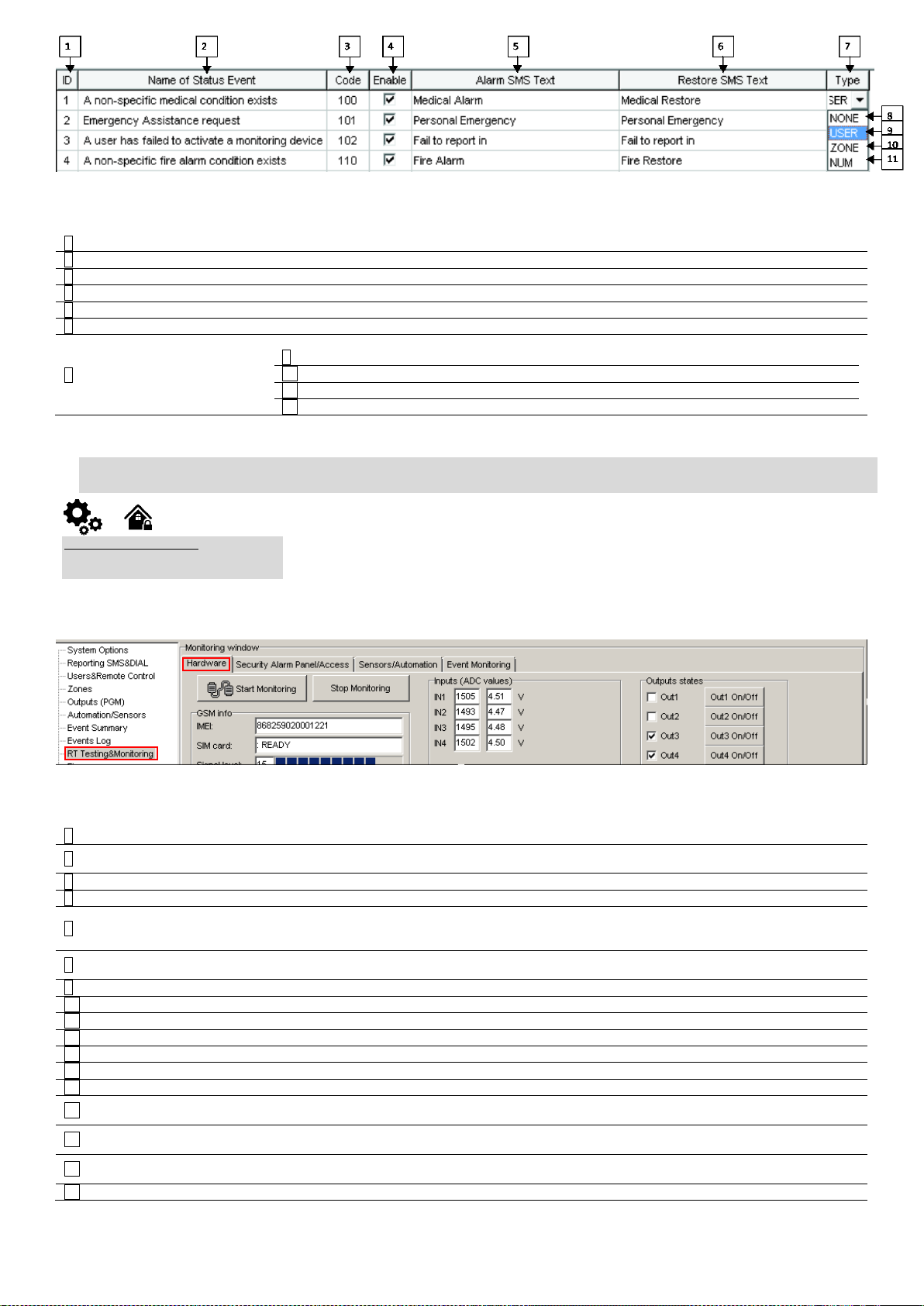
Figure 62 the example Event Summary (Events) window
2
ID
Report sequence number
3
Name of Status Event
Event (report) name
4
Code
Report Contact ID code.
5
Enable
The indicated report will be sent when it is checked.
6
Alarm SMS Text
Alarm text which will be visible in SMS message is entered.
7
Restore SMS Text
Restore text which will be visible in SMS message is entered.
8
Type
9
None
10
USER
Refer to USER Report Options
11
ZONE
Refer to Zone Report Options
12
NUM
Refer to Numerical Report Options
RT Testing & Monitoring > Hardware
The Hardware monitoring window let you see real time input, output actions and GSM information.
Thus it would be easier to evaluate whether the input, output actions, registration to the network
operates as appropriate.
3
IMEI
IMEI number of GSM modem available in the module
4
SIM Card
If note READY is visible, it means that SIM card is fully functioning. Otherwise, check whether PIN
code request is off or replace SIM card.
5
Signal level
Signal strength of GSM communication
6
Registration
State of GSM modem registration to GSM network.
7
SMS Service Centre Address
SMS center number. This number should be checked if it is correct. If this number is incorrect. SMS
messaging may be impossible. This number may be changed after inserting SIM card into any
mobile phone.
8
System Voltage
Power supply voltage. Nearby number is value of ADC voltage. When multiplying this number by
the coefficient Fig. 32, voltage value (V) will be achieved.
9
System Voltage
System voltage OK/Trouble
10
RTC Clock
Real time clock OK/Trouble
11
Module Real Time Clock
Indicates the time of the module RTC
13
Inputs In1…In4
In1…In4 is the indicated input ADC and voltage value V.
14
I/O1…I/O2
I/O1…I/O2 is the indicated voltage ADC value and current ADC value mA.
15
D1…D3 (I/O)
Check box nearby the digital inputs D1…D3 (I/O) means that the input has ‘0’ or ‘1’ state.
16
BUS (I/O)
Check box nearby the zone expansion module BUS (I/O) means that the input has ‘0’ or ‘1’ state.
17
Out1…Out4 On/Off
Checked box nearby the appropriate output Out1…Out4 means that this output currently has ‘0’ or
‘1’ state. The output could be activated by pressing On/Off button
18
I/O1…I/O2 On/Off
Checked box nearby the appropriate output I/O1…I/O2 means that this output currently has ‘0’ or
‘1’ state. The output could be activated by pressing On/Off button
19
D1…D3 (I/O) On/Off
Checked check box nearby the digital outputs D1…D3 (I/O) means that the output currently has ‘0’
or ‘1’ state.
20
BUS (I/O) On/Off
Checked check box BUS (I/O) means that the output currently has ‘0’ or ‘1’ state.
Table 18 Explanation of every field in "Event Summary" window
4.1. RT Testing & Monitoring. Hardware.
Figure 63 How to find required RT Testing & Monitoring > Hardware window
Table 19 Explanation of every field in "Hardware" window
Page 40
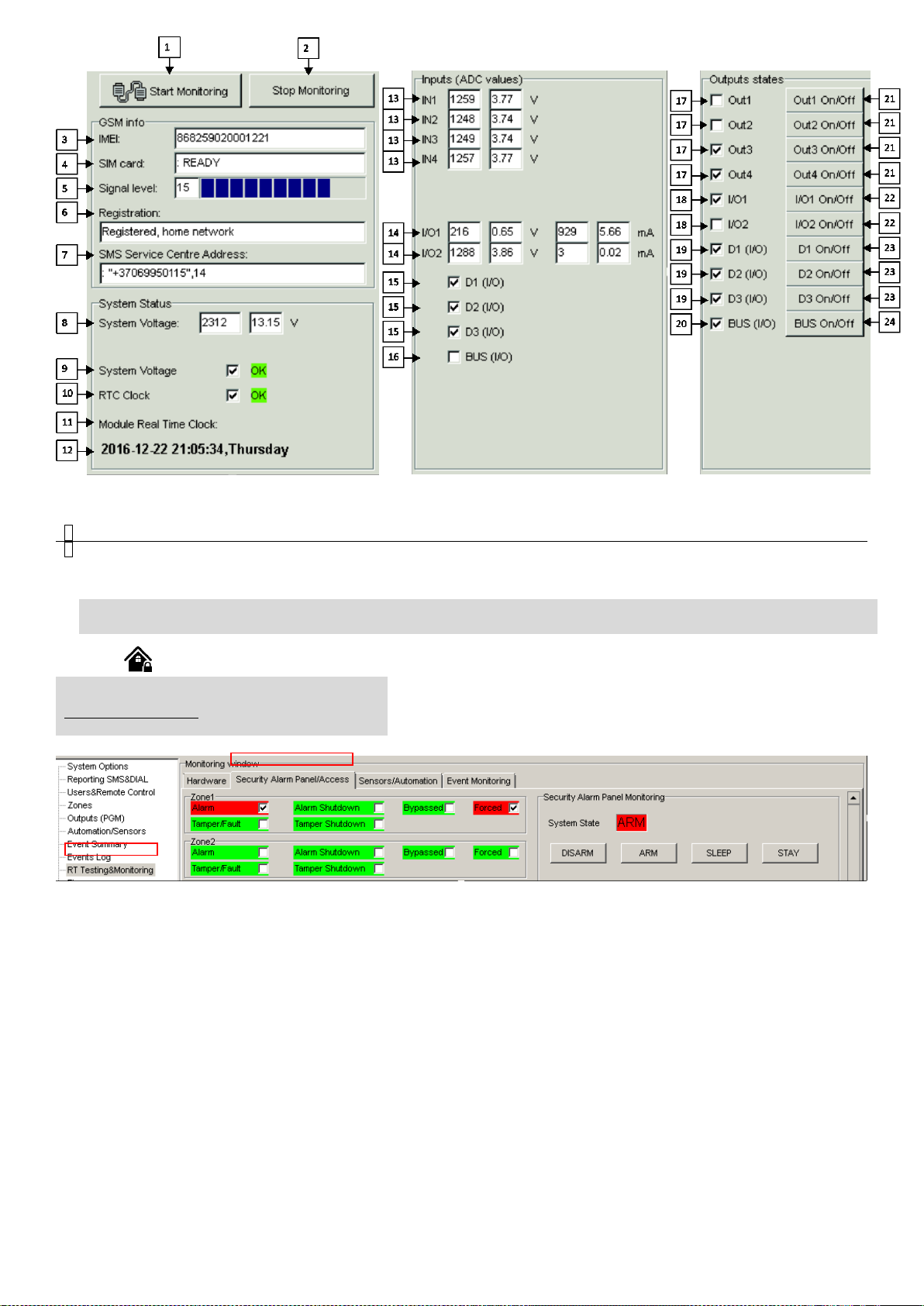
Figure 64 The example of RT Testing & Monitoring > Hardware window
1
Start Monitoring
Pressing Start Monitoring button starts the monitoring of the module.
2
Stop Monitoring
Pressing Stop Monitoring button stops the monitoring of the module.
RT Testing & Monitoring > Security Alarm Panel/ Access
The Security Alarm Panel/ Access window let you see real time zones states: is zone
alarmed, bypassed, forced etc. This window it let you change system state: disarm,
arm, sleep, and stay. This window let you look to access control area also.
Table 20 Explanation of every field in "Hardware" window
4.2. RT Testing & Monitoring Security Alarm Panel/ Access
Figure 65 How to find required RT Testing & Monitoring > Security Alarm Panel/ Access window.
Page 41
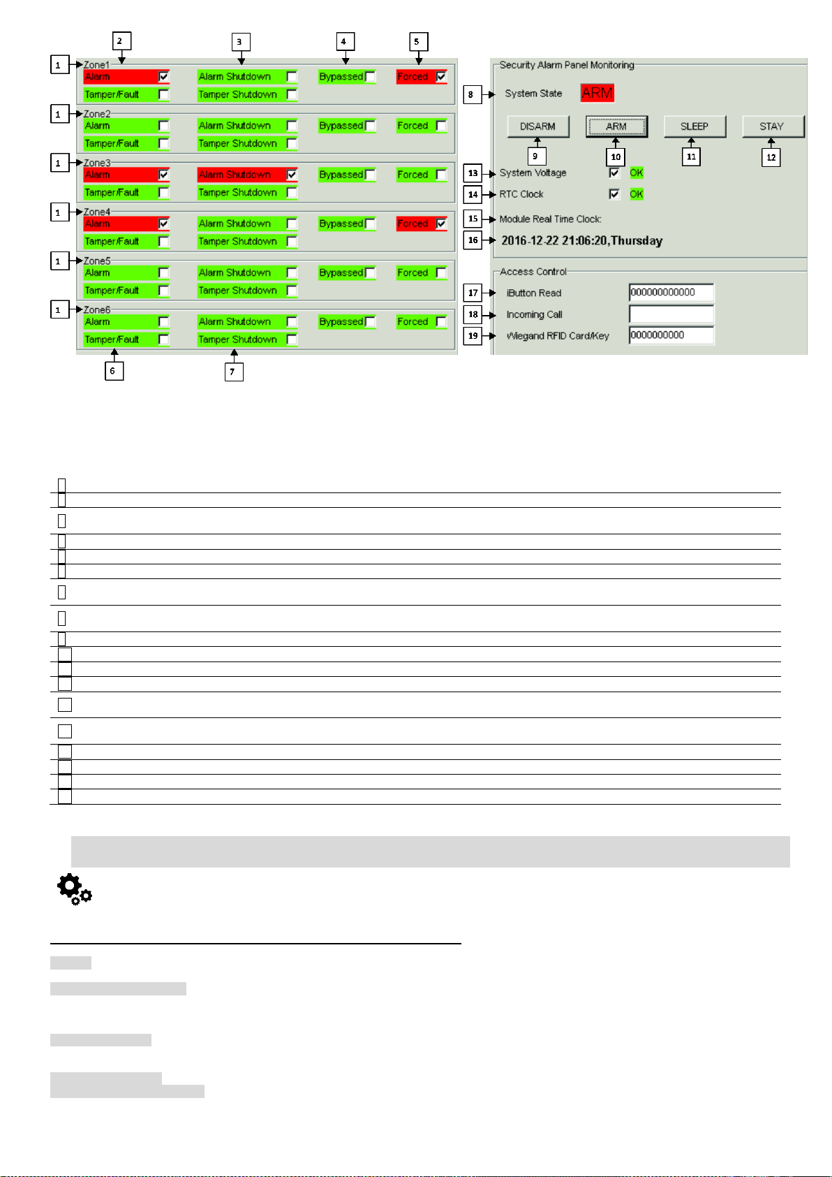
Figure 66 the example of RT Testing & Monitoring > Security Alarm Panel/ Access window
1
Zone1…Zone32
Zone number
2
Alarm
If checked and the color is red the zone is alarmed
3
Alarm Shutdown
If checked and the color is red alarm shutdown for the zone is activated. Allowable number of
the same alarm events is reached and the same events will not be reported.
4
Bypassed
If checked and the color is red, the zone is bypassed.
5
Forced
If checked and the color is red, the zone is forced
6
Tamper/Fault
If checked and the color is red, the zone is tampered.
7
Tamper Shutdown
If checked and the color is red tamper shutdown for the zone is activated. Allowable number of
the same tamper shutdown events is reached and the same events will not be reported.
8
System State
Indication that at the moment the module is in waiting ARM, ARM, DISARM, SLEEP or STAY
mode
9
DISARM
After pressing the button DISARM, disarm mode should be entered
10
ARM
After pressing the button ARM, arm mode should be entered
11
SLEEP
After pressing the button SLEEP, sleep mode should be entered
12
STAY
After pressing the button STAY, arm mode should be entered
13
System Voltage
If the checkbox is checked and the color is red the trouble with system voltage is indicating. If
color is green, there is no trouble with system voltage.
14
RTC Clock
If the checkbox is checked and the color is red RTC clock is not set. If color is green, RTC clock
is set.
15
Module Real Time Clock
Real time and date is indicating.
17
iButton Read
The number of iButton Maxim iButton key DS1990A - 64 Bit ID code that is arming the system.
18
Incoming call
The number of users phone that is calling to the module’s SIM.
19
Wiegand RFID Card Key
The number of Wiegand RFID Key Card that is arming the system.
If the checkbox is checked and the color is red the trouble is indicating. If color is green, trouble is not indicated. The text nearby indicates the
trouble.
Table 21 Explanation of every field in "Security Alarm Panel/ Access" window
4.3. Automation & Sensors Programming
The most important information due to automation with the module GTalarm2
Sensors. The module can receive signals from standard sensors that produce a standard analog or pulse output. Sensor’s parameters should be set
by SERA2 software.
Remote Monitoring, Control It is possible to monitor, control or log data by using GSM GPRS network from almost any location around the world. The
data transmitting via GPRS using TCP/IP protocol; the GSM module connects to the internet via a GPRS cannel to SeraServer server tool who
registering all devices. The connection is established by the SERA2 configuration tool using unique id. The SeraServer is designed to make setup
and use fast and easy setup and configuration.
Remote monitoring. Using the GSM, GPRS remote access from the simplest application, viewing data to more sophisticated uses, such as sending
a text message when an alarm occurs or transmitting a data log file over the internet from a remote location to a central office. A user can access this
data anytime, anywhere.
Testing & Monitoring. You need to monitor the temperature, humidity maybe even the security
Localized Monitoring Systems. Perfect for many applications, SeraServer technology can be used in labs, clean rooms, museums, warehouses,
computer rooms, food processing/storage, hospitals, and greenhouses, as well as HVAC, pharmaceutical, electronic assembly, and many more
environments. Depending on your specific application, you can monitor ambient temperature, humidity, or use a thermocouple or other process.
Page 42
Sensor with analog voltage/current or pulse output, and make the data available anywhere. The Sera Server can be configured quickly and easily
Connect the GSM antenna to the antenna connector. Insert the SIM card in the SIM card holder. Ensure that PIN request function is disabled.
Connect the battery
Set general system details
System Times (entry delay): General system options programming
Installer Password: General system options programming
User Password: General system options programming
System Options (Bell squawk, Door Chain ): General system options programming
Test Transmission Time of Day: General system options programming
Periodic Test Transmission: General system options programming
Set Clock: General system options programming
Restore Control Panel to Default: General system options programming
Auto-reArm: General system options programming
Panel Version Displayed
Expansion Programming
Installer Walk Test Mode
Set zones parameters
Zone Definitions: Zones programming
Set access control details
Wiegand Keypad & RFID Reader settings: Wiegand Keypad & RFID card reader programming
Set Outputs (PGM)
PGM Output Attributes Programming:
Outputs. Bell & PGM programming
PGM Output Timer:
Outputs. Bell & PGM programming
Set reporting to user mobile phone
Maximum Dialing Attempts to Each Telephone Number: Reporting to the user‘s mobile phone
1. Connect AM2320 or AM2302 to D1, D2, D3 according connection diagram.
2. Sensor’s type should be select in the System Options> Digital I/O Settings window. Set digital input definition D1, D2, D3 to Aosong 1 Wire
bus Humidity Sensor AM2302
3. Write configuration
4. Power module.
5. After module starts , read configuration
6. Go to “Automation/ Sensors” window in the SERA2 software
7. Double click on the selected sensor’s line.
8. Click on “Sensor type/ hardware location” and default sensor settings appear.
9. In sensors table column Sensor HW ID find registered sensors AM2302 looks like "GTalarm, Input D1, 1-Wire, AM2302 Huminidty,
28AE51560500" Location of the sensor can be changed choosing wanted sensor in the list
10. Double click on the sensor row opens selected sensor window
11. Set other parameters of the sensor MIN, MAX values Units etc.
12. Write configuration to module
13. Open RT Testing&Monitooring Window > Hardware. Press [Start monitoring] button
14. Go to RT Testing&Monitooring Window > Event Monitoring TAB. Software will show real time sensor values, and alarm states
15. If you need to receive sms with sensors alarm, go to GSM communication> SMS/ DIAL Reporting window
you can even use a SERA2 program.
Step by step to set the parameters of security system:
Installation:
Install the module GTalarm2 and sensors (PIR, smoke detectors, door contacts
Connect the power supply
Connect the sensors (PIR, smoke detectors, door contacts) to the module GTalarm2, according connecting diagrams
Connect Bell, Siren to the output of the GTalarm2, according connecting diagram
Connect Wiegand keypad and RFID reader, according connecting diagram
Configuration:
Install SERA2 software
Connect the module to the computer via mini USB cable.
Configure sensors parameters
Configure PGM outputs
Enter user phone numbers for system parameters monitoring
Read information about arming/ disarming and systems operation algorithm
Enter user phone numbers for remote control of the outputs
Set reporting to server details
Read event Log
Real time sensors inputs, system outputs monitoring
Sometimes it is useful security system’s details for automation purpose:
Table 22 Security system's details
4.4. Sensors Configuration
4.4.1. Humidity sensors AM2302/DHT22/AM2305/AM2306/AM2320/AM2321 Configuration
Steps to start AM2320 and AM2302 sensors:
Page 43
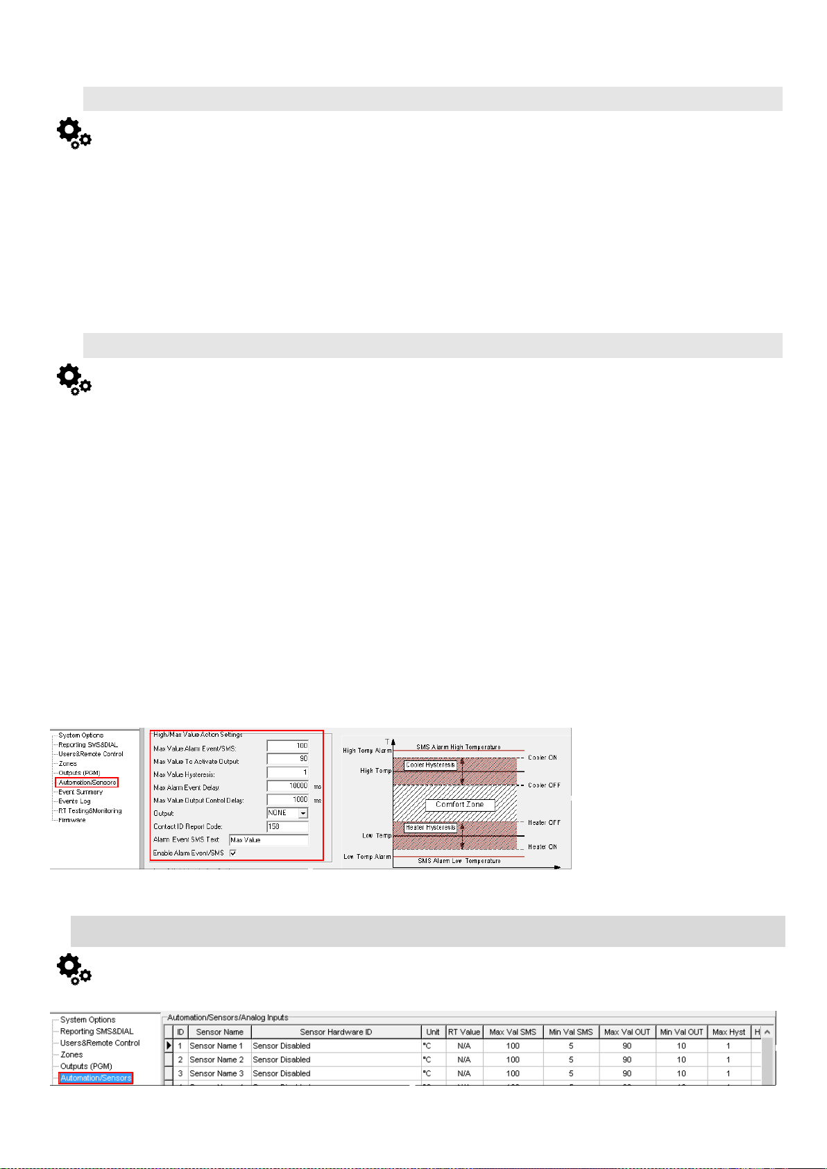
16. Enter telephone numbers of users and mark alarm events that you want to receive. Open "Reporting SMS&DIAL" window. Set user phone
number, and choose reporting option Sensor1 - Sensor32 Alarm/Restore. Module will send SMS to user then sensor alarm event occurs
17. Write configuration
10. Connect analog voltage sensors to In1, In2, In3 and connect analog current sensors to I/O1, I/O2 according connection diagram.
11. The analog sensors can be used with security system sensors, if required.
12. If security system sensors is not in use, the inputs should be disabled in “Zones” window.
13. Analog sensors should be calibrated in the Automation/Sensors window. Double click on the selected sensor’s line. Analog sensors could
be selected from the default list. Units could be changed. Sensors calibration is possible by changing multiplier, offset.
14. When all changes has been done, the configuration should be written, by pressing write icon.
15. Open RT Testing&Monitooring Window > Hardware. Press [Start monitoring] button
16. Go to RT Testing&Monitooring Window > Event Monitoring TAB. Software will show real time sensor values, and alarm states
17. If you need to receive sms with sensors alarm, go to GSM communication > SMS/ DIAL Reporting window. Enter telephone numbers of
users and mark alarm events that you want to receive. Open "Reporting SMS&DIAL" window. Set user phone number, and choose reporting
option Alarm/Restore. Module will send SMS to user then sensor alarm event occurs
18. Write configuration
18. Connect 1-Wire sensors DS18b20 to D1, D2, D3 according connection diagram. Connect the sensors as showed in the figures below. If
you need to connect more sensors to the same input, connect them as a star or serial.
19. Sensor’s type should be select in the System Options> Digital I/O Settings window. Set digital input definition D1, D2, D3 to Dallas 1-Wire
Bus option.
20. Write configuration
21. Power module.
22. After module starts , read configuration
23. Go to “Automation/ Sensors” window in the SERA2 software
24. Double click on the selected sensor’s line.
25. Click on “Sensor type/ hardware location” and default sensor settings appear.
26. In sensors table column Sensor HW ID find registered sensors DS18b20 looks like "GTalarm, Input D1, 1-Wire, DS18B20 Temperature,
SN:28AE51560500" Location of the sensor can be changed choosing wanted sensor in the list
27. Double click on the sensor row opens selected sensor window
28. Set other parameters of the sensor MIN, MAX values Units etc.
29. Write configuration to module
30. Open RT Testing&Monitooring Window > Hardware. Press [Start monitoring] button
31. Go to RT Testing&Monitooring Window > Event Monitoring TAB. Software will show real time sensor values, and alarm states
32. If you need to receive sms with sensors alarm, go to GSM Communication> SMS/DIAL Reporting window. Enter telephone numbers of
users and mark alarm events that you want to receive. Open "Reporting SMS&DIAL" window. Set user phone number, and choose reporting
option Sensor1 - Sensor32 Alarm/Restore. Module will send SMS to user then sensor alarm event occurs
4.4.2. Analog inputs 0-10V, 0-20mA, 4-20mA Configuration
Step by step to start analog sensors:
4.4.3. Temperature sensors Dallas 1-wire DS18b20 Configuration
Step by step to start DS18b20 sensors:
33. Clear or disable sensor from the module:
34. Go to “Automation/ Sensors” window
35. In the column Sensor HW ID find registered sensors and set to disable
36. Write configuration
Figure 67 How to find Automation/ Sensors window
4.1. Automation/Sensors (Automation/Sensors/Analog Inputs) Programming in SERA2 Software
Figure 68 How to find required Automation/Sensors (Automation/Sensors/Analog Inputs) window.
Page 44
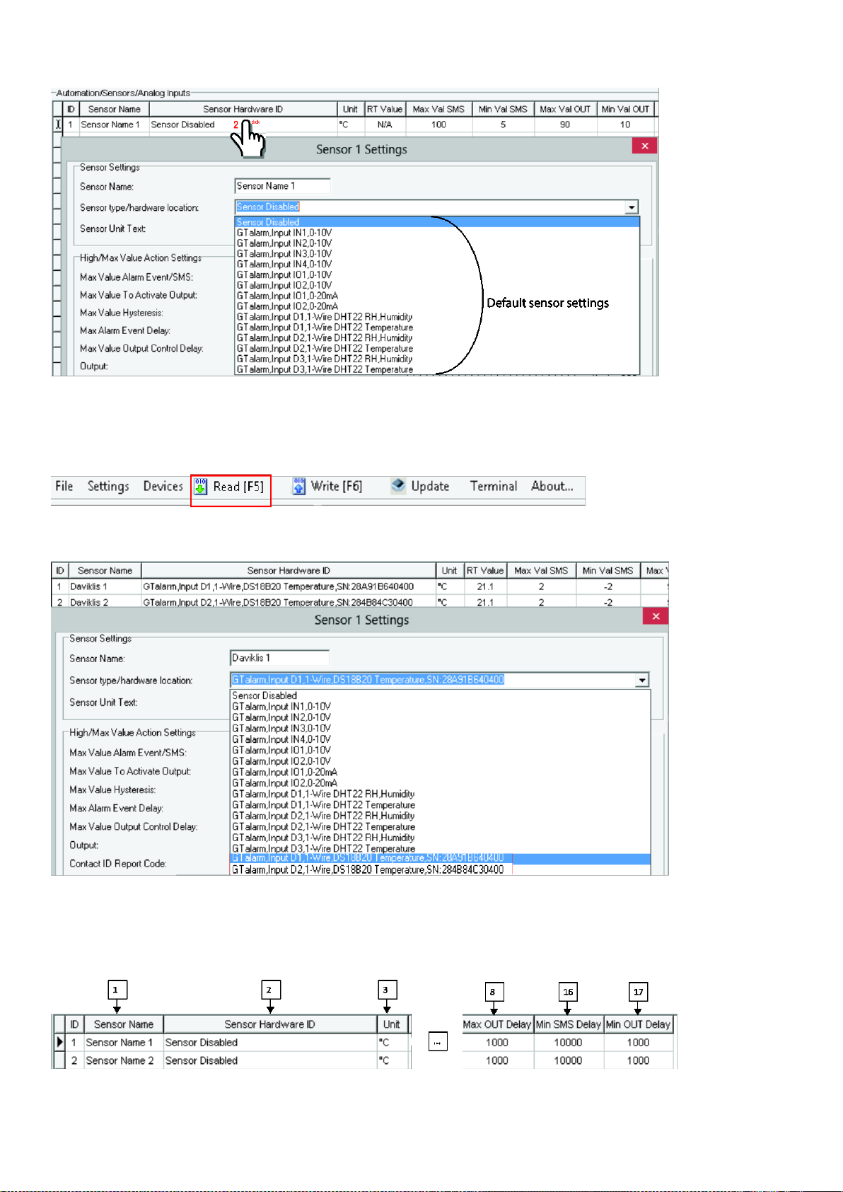
How to connect sensor’s to the module:
1. Double click on the selected sensor’s line.
2. Click on “Sensor type/ hardware location” and default sensor settings appear.
Figure 69 the example of Automation/Sensors (Automation/Sensors/Analog Inputs) window
3. Connect the sensors to the module. Connect the power supply.
Sensor’s type should be select in the System Options> Digital I/O Settings window.
4. Click “Read”.
Figure 70 How to find required Read icon.
5. The connected sensors will appear in the list.
Figure 71 the example of Automation/Sensors (Automation/Sensors/Analog Inputs) window
How to set sensor’s parameters:
Double click on the selected sensor’s line will show selected sensor’s configuration window.
Figure 72 the example of Automation/Sensors (Automation/Sensors/Analog Inputs) window
For example double click on “Sensor Name 1” line will show “Sensor 1 Settings” window. The required parameters of the sensor 1 can be set in that
window.
Page 45
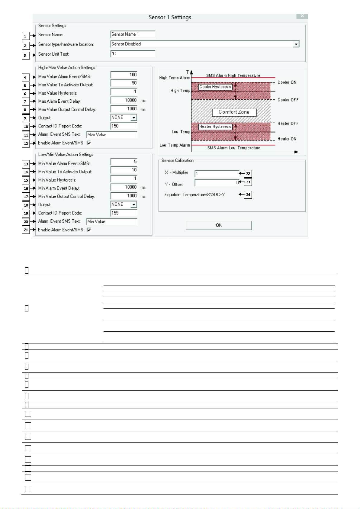
Figure 73 the example of Automation/Sensors (Automation/Sensors/Analog Inputs) window
1
Sensor Name
Sensor name
2
Sensor Type/
Hardware location
Select the sensor type hardware location
Location of sensor connected to the module. Select connected sensors
Sensor disabled
GTalarm, Input IN1…IN4, 0-10V
Voltage input IN1… IN4, 0-10V assigned
GTalarm, Input I/O1…I/O2, 0-10V
Voltage input. I/O1…I/O2 0-10V assigned
GTalarm, Input I/O1…I/O2, 0-20mA
Current I/O1…I/O2 , 0-20mA assigned
GTalarm, Input D1…D3, 1-Wire DHT22 RH,
Humidity
Digital input D1…D3, 1-Wire DHT22 RH, Humidity
assigned
GTalarm, Input D1…D3, 1-Wire DHT22 RH,
Temperature
Digital input D1…D3, 1-Wire DHT22 RH, Temperature
assigned
1-Wire Temperature sensors
Digital input D1…D3, 1-Wire DS18b20 Temperature
sensor
3
Sensor Unit Text
Sensor Unit Text
4
Max Value Alarm Event/
SMS
Maximum allowable temperature value, which will be reported.
5
Max Value To Activate
Output
Maximum allowable temperature value, which will activate the selected output
6
Max Value Hysteresis
Temperature hysteresis value is indicated.
7
Max Alarm Event
Delay
……………
8
Max Value output
Control Delay
……………
9
Output
The output which will be activated, when the maximum allowable temperature value will be reached
10
Contact ID Report
Code
Report Contact ID code
11
Alarm Event SMS
Text
Text, which will be visible in SMS message in case of set temperature excess, is entered.
12
Enable Alarm Event/
SMS
The indicated report will be sent when it is checked.
13
Min Value Alarm Event/
SMS
Minimum allowable temperature value, which will be reported.
14
Min Value To Activate
Output
Minimum allowable temperature value, which will activate the selected output.
15
Min Value Hysteresis
Temperature hysteresis value is indicated.
16
Min Alarm Event
Delay
……………
17
Min Value Output
Control Delay
……………
Table 23 Explanation of every field in "Automation/ Sensors" window
Page 46
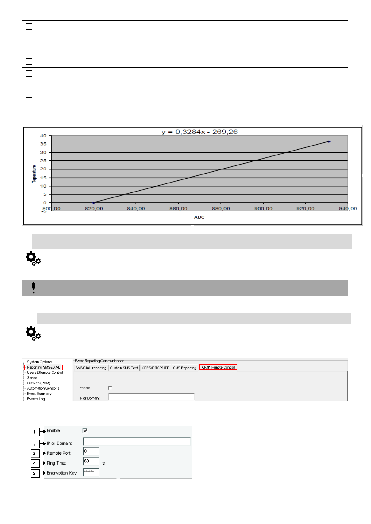
18
Output
The output which will be activated, when the minimum allowable temperature value will be reached
19
Contact ID Report
Code
Report Contact ID code
20
Alarm Event SMS
Text
Text, which will be visible in SMS message in case of set temperature excess, is entered.
21
Enable Alarm Event/
SMS
The indicated report will be sent when it is checked.
22
X-multiplier
X-multiplier coefficient. Following the equation “Temperature=X*ADC+Y“to calculate X and Y coefficients.
Measure temperature in two points at least.
23
Y-offset
Y-offset coefficient. Following the equation “Temperature=X*ADC+Y“to calculate X and Y coefficients.
Measure temperature in two points at least.
24
Temperature=
X*ADC+Y
21
Max CID
Max and Min Contact ID report codes. Report codes are the Ademco CID, SIA DC09 format. The module
can automatically program a set of default report codes. The Contact ID Reporting Format can be modified
and changed. Enter any of the desired text in the “Alarm SMS Text” field.
22
Min CID
Fig ilustrate how to calculate X-multiplier and Y-offset with excell chart.
GPRS/ IP/ TCP/ UDP details must be configured before TCP/IP Remote control will be set
Reporting SMS & DIAL > TCP/ IP Remote Control
The TCP/ IP Remote Control window let you set basic TCP IP remote control
settings and enable or disable remote communication.
Figure 75 The example of Reporting SMS & DIAL > TCP/ IP Remote Control window
4.2. Data Transmiting to Server & Remote Control
It was discussed in GPRS/ IP/ TCP/ UDP details programming
4.2.1. TCP/ IP Remote Control
Figure 74 How to find required Reporting SMS & DIAL > TCP/ IP Remote Control window.
Table 5 explains every field in the of Reporting SMS & DIAL > TCP/ IP Remote Control window
Page 47
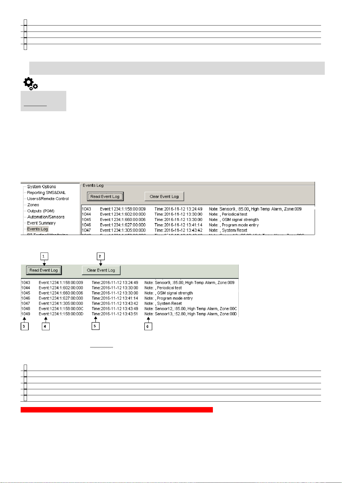
Table 24 Explanation of every field in "TCP/ IP Remote Control" window
1
Enable
Check the particular checkbox to enable remote control/configure module over internet.
2
IP or Domain
IP address xxx.xxx.xxx or domain name of remote control server.
3
Remote Port
Remote server port.
4
Ping Time
Period of communication test signal PING sending via GPRS channel.
5
Encryption Key
Server encryption key
.
Events Log
The Event Log window show real time information of the events that has been occurred
1
Read Event Log
Events could be read from the module by clicking Read Event Log button
2
Clear Event Log
Events could be cleared from the module by clicking Clear Event Log button
3
Event Number
Event sequence number
4
Event
Object number and registered event report in Contact ID code.
5
Time
Event date and time.
6
Note
Event report text which was indicated.
4.3. Events Log
The event log allows to chronologically register up to 2048 time stamped records regarding the following system events:
System start.
System arming/disarming.
Zone violated/restored.
Tamper violated/restored.
Zone bypassing.
Temperature deviation by MIN and MAX boundaries.
System faults.
Configuration via USB.
User phone number that initiated the remote configuration.
Communication with monitoring station status.
Figure 76 How to find required Events Log window.
Figure 77 the example of the Events Log window.
Table 5 explains every field in the Events Log window.
Table 25 Explanation of every field in "Events Log" window
To export the event log to .log file or clear it, please refer to the following configuration method.
Page 48
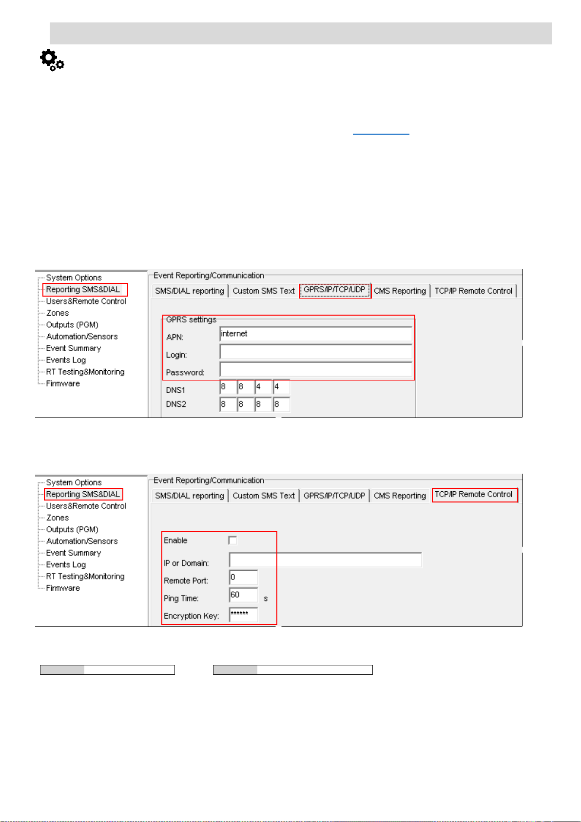
4.4. Remote Monitoring, Control, Configuration, FW update over the internet
GPRS network settings
INST000000˽008˽APN#LOGIN#PSW#
008= command code (GPRS network settings)
APN=31 symbols
LOGIN=31 symbols
PSW=31 symbols
Remote control of the module over the Internet.
INST000000˽009˽ADDR#PORT#PING#KEY#
009= command code (Remote control of the module over the Internet)
ADDR = the format of IP address xxx.xxx.xxx.xxx (the numbers from 0 to 255 should be
separated by dot or domain text length of up to 47 characters)
PORT= TCP port number from 1 to 65535
PING= communication control ping time from 30 to 9999s
KEY= encryption key. Encryption key should be the same as server key. Default 123456
The data are via GPRS using TCP/IP protocol; the GSM module connects to the internet via a GPRS cannel to SeraServer server tool who registering
all devices. The connection is established by the SERA2 configuration tool using unique id of the module UID IMEI.
GTalarm2 SeraServerSERA2
SeraServer opens tunnel between two clients GTalarm2 and SERA2 and lets them communicate to each other via TCP protocol.
SERA2 and SeraServer software are downloadable from the website of the manufacturer at www.topkodas.lt
Two critical conditions are necessary to establish connection over the internet:
Steps to activate Remote control over internet:
The system parameters may be changed and the system status, temperature sensors may be observed by connecting over the internet.
1. GPRS service should be activated for the SIM card of the GSM module. Usually GPRS service is activated automatically otherwise need
contact GSM service provider to inquire about activation of the GPRS service.
2. The GSM module or the computer that is used for connection to the GSM module should have public IP addresses. What is public IP
address? A public IP address is the address that is assigned to a computing device to allow direct access over the Internet. A web server,
email server and any server device directly accessible from the Internet are candidate for a public IP address. A public IP address is globally
unique, and can only be assigned to a unique device. If PC is in local network, TCP port forwarding must be enabled in router to computer
were SeraServer software is run.
1. Install SERA2 software
2. Go to “Reporting SMS & Dial” window, “GPRS/IP/TCP/UDP” table.
3. Set APN, Login, Password.
4. Write the configuration into the module by pressing “Write” icon
Figure 78 How to find Reporting SMS& Dial GPRS/IP/TCP/UDP window
5. Go to “Reporting SMS & Dial” window, “TCP/IP Remote control” table.
6. Public IP or domain must be entered. Enter remote port, ping time, encryption key and enable the communication.
Figure 79 How to find Reporting SMS&DIAL TCP/IP Remote Control window
7. If needed, APN/Password/Login/IP/Domain/ Port /PING time /KEY can be set via SMS commands
8. Enable port forwarding on router
Page 49
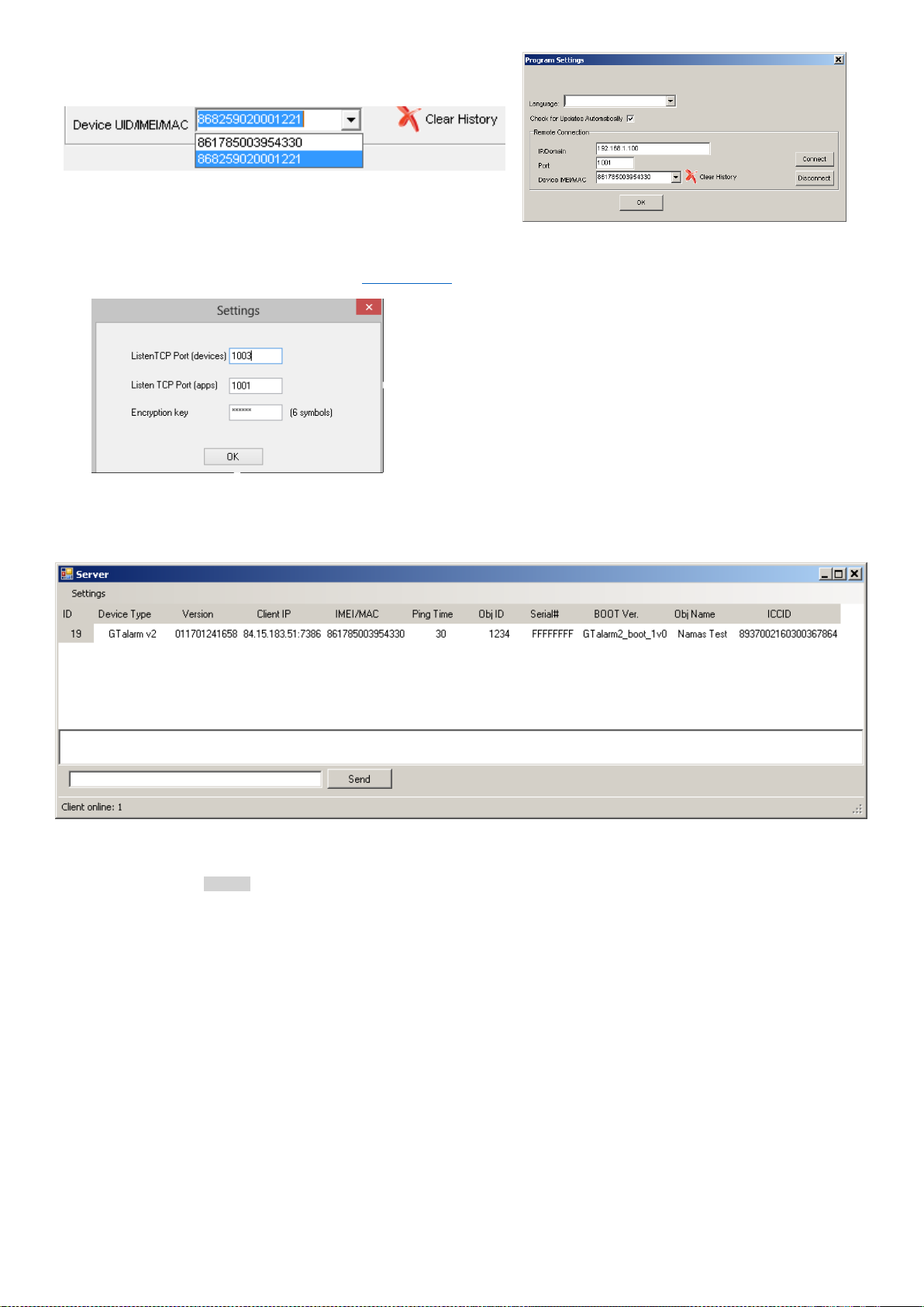
For example: GTalarm2 port is 1000 then you have to enable 1000 port
forwarding to PC were SeraServer is run.
SERA2 software can remember all IMEI that was entered in the past. If needed
to clean the list UID/IMEI, press “Clear History”.
Figure 80 The example of IMEI history and "Clear History" button.
Figure 81 The example of SeraServer program
Set devices Listen TCP Port
Set apps Listen TCP Port
Encryption key must be the same as in device
Press ok
Figure 82 The example of SeraWebServer window
Table 26 The example of Program Settings window
9. Install SeraServer program. You can find it in www.topkodas.lt website.
10. Double click on “Setting” in the SeraServer program. The settings window will appear.
11. When server is configured and started , active modules will appear in server list:
12. In the SERA2 command line press on “Settings” and set Remote connection parameters: enter server IP/Domain, Port and device
UID/IMEI. Press Connect button and wait till connection will be established. In the bottom in the task bar appears TCP connected
notification.
Page 50
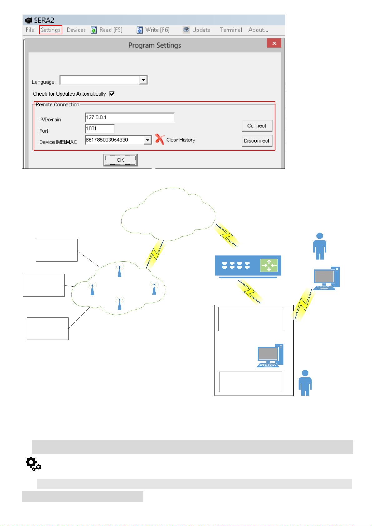
Figure 83 the example of SERA2 software settings window
Gtalarm2
Module1
Gtalarm2
Module2
Gtalarm2
Module3
Router
SERA2
SeraWebServer
Device TCP PORT
SERA2 TCP PORT Localhost IP
Device
TCP PORT
Public IP
Public internet
Gtalarm2 TCP Port fowarding to PC
Device TCP PORT
SERA2 TCP PORT Localhost IP
USER1
USER PC
USER2
SERA2 TCP PORT
GSM Network
Figure 4-84 Remote control via internet working diagram.
4.5. Testing & Monitoring Automation
4.5.1. RT Testing & Monitoring > Sensors/ Automation
Page 51

RT Testing & Monitoring > Sensors/ Automation
The Sensors/ Automation window let you see real time sensors states: is the sensor
active, does it reaches high or low value alarm.
1
Sensor1…Sensor32
Sensor number
2
Value
The value of sensor’s voltage
3
Active
If checked and the color is green, the sensor is active
4
High Val Alarm
If checked and the color is red, the high value alarm is generated
5
Low Val Alarm
If checked and the color is red, the low value alarm is generated
RT Testing & Monitoring > Event Monitoring
The Event Monitoring window will show real time events information
Figure 88 The example of RT Testing & Monitoring > Event Monitoring window
3
…
Event number
4
CID
Contact ID Code
5
Time
Event date and time
6
Note
Event report text which was indicated.
System Options > System Info
The System Info window let you take a look to the main hardware, boot loader,
firmware, serial no, IMEI, ICCID information.
Figure 85 How to find required RT Testing & Monitoring > Sensors/ Automation window
Figure 86 the example of RT Testing & Monitoring > Sensors/ Automation window
Table 27 Explanation of every field in "Sensors/ Automation" window
4.5.2. RT Testing & Monitoring > Event Monitoring
Figure 87 How to find required RT Testing & Monitoring > Event Monitoring window.
Table 28 Explanation of every field in "Event Monitoring" window
5. Info: Hardware, Firmware, Bootloader, Serial No & Updates
Page 52
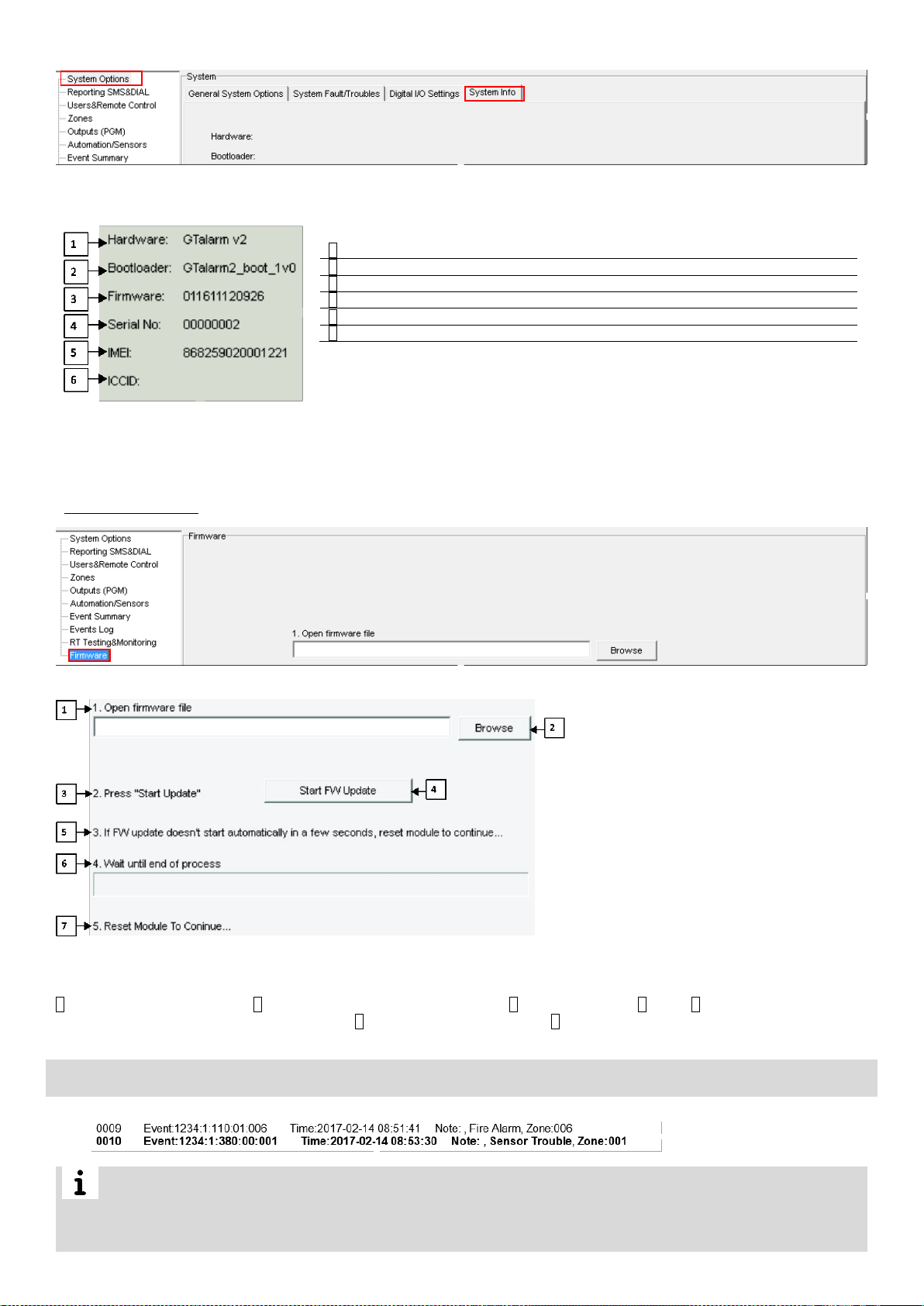
Figure 90 The example of "System
Info" window
Table 29 Explanation of every field in "System Info" window
1
Hardware
Control panel type.
2
Bootloader
Bootloader version
3
Firmware
Configuration software
4
Serial No
Module registration number
5
IMEI
GSM modem IMEI address.
6
ICCID
(Integrated Circuit Card Identifier) identifies each SIM internationally.
RT Testing & Monitoring > Firmware
The Firmware let you update the firmware of the module
What should you do, if you noticed, that there is Sensor trouble in the “Event Log” window?
It is comfortable to use “RT Testing&Monitoring” window. Red field indicates sensor’s troubles.
Go to Automation/ Sensors window, disabling this sensor and press “W rite”. Maybe there is the problem with sensor’s connection to the
module.
If the problem still exist, please read, save and send the configuration to the seller. Describe what and how is connected to zone: 001
and send this information to the seller.
Figure 89 How to find required System Options > System Info window.
Figure 91 How to find required RT Testing & Monitoring > Firmware window
Figure 92 the example of RT Testing & Monitoring > Firmware window
1 Open firmware file: press Browse 2 and open the folder containing firmware file. 3 Press “Start Update” 4 button. 5 If firmware update does not
start in a few seconds, reset the module to continue… 6 Wait until the end of the process. 7 Press the reset button to continue…
6. Recommendations for the user & installer
Page 53
7. Remote control and configuration using SMS Commands
Users allowed:
Installers allowed:
Control outputs,
Control outputs
Arm/disarm the system or select stay, sleep mode
Arm/disarm the system or select stay, sleep mode
Bypass zones
Bypass zones
Set the time of the module
Set the time of the module
Request zone test and system state
Request zone test and system state
Forward messages to other number
Forward messages to other number
Enter/ deleting user phone numbers
Set periodical test,
Set GPRS network settings
Remote control via Internet
Activate/ deactivate connection to the remote control server.
Enter/ deleting iButton keys
Change sensor’s values
Request module configuration information
Change user, installer password
The module could be controlled only by these users, whose phone numbers entered in the memory of the module
- Identification:
INST – Install used for module’s configuration.
- Installer’s or user’s password.
- space character
- Command code.
- space character
- First configuration array
- space character
- Second configuration array
- etc.
- Identification:
USER – User used for module’s control.
- Installer’s or user’s password.
- space character
- Command code.
- space character
- First configuration array
- space character
- Second configuration array
- etc.
INST000000˽001˽N#TEL#SMS#DIAL#
Programming of users telephone numbers to send SMS and to make a call if the event occur:
001= programming user‘s tel. numbers for DIAL and send SMS
N = user ID number 1-8
TEL = user‘s telephone number (max 16 digits) without (+) country code, operator‘s code and user‘s
telephone number included. The end symbol #;
SMS = event filter for sms. 1- send event, 0- don’t send event. Sequence of the events 1.2.3...n For example:
001000
DIAL = event filter for DIAL. 1-DIAL if the event occur, 0-don‘t DIAL Sequence of the events 1.2.3...n For
example: 101000
#= delimiter
INST000000˽002˽N
Delete user’s phone number according the user ID number. Phone number used for receive user’s
information.
002= command code (deleting user‘s numbers according the user ID number)
N = user ID number from 1 to 8
INST000000˽004˽N#TEL#OUT#OPT#
To enter user‘s telephone number for remote control via short call
004= command code (enter user‘s telephone number for remote control via short call)
N = user ID number 001-800
TEL = user‘s telephone number (max 16 digits) without (+) comprised of country code, operator‘s code and
user‘s telephone number. the end symbol #;
OUT= output number, that will be controlled, 1-10.
OPT = DIAL function: 0 – disabled 1 – enabled, Sequence from the left to the right: ARM/ DISARM, MIC. For
example: 010
INST000000˽005˽TEL
To delete user‘s phone number for remote control, according phone number
005= command code (delete user‘s phone number for remote control, according phone number)
TEL = user‘s phone number (max 16 digits) without (+) comprised of country code, operator‘s code and
user‘s telephone number. User‘s phone number must be the same as in the memory of the module.
INST000000˽006˽N
Delete user‘s phone number whose ID number is N.
006= command code (Delete user‘s phone number according user‘s ID number )
N = user‘s ID number from 001 to 800.
INST000000˽007˽P#PER# HH:mm#
Automatic periodical test settings
007= command code (Automatic periodical test)
P= 0-test disabled, 1- test period by 24 hours, 2- period by minutes
PER= automatic test sending period from 1 to 99999 days or minutes
HH-hours 0-23 ,
mm- minutes 0-59
Installer code – 6-digit password used for system configuration, control and request for information. By default, installer code is 000000, which
is highly recommended to change.
User code – 6-digit password used for system control and request for information. By default, installer code is 000000, which is highly
recommended to change.
7.1.1. The table of installers commands
Table 30 The table of installers commands
Page 54
INST000000˽008˽APN#LOGIN#PSW#
GPRS network settings
008= command code (GPRS network settings)
APN=31 symbols
LOGIN=31 symbols
PSW=31 symbols
INST000000˽009˽ADDR#PORT#PING#KEY#
Remote control of the module over the Internet.
009= command code (Remote control of the module over the Internet)
ADDR = the format of IP address xxx.xxx.xxx.xxx (the numbers from 0 to 255 should be separated by dot or
domain text length of up to 47 characters)
PORT= TCP port number from 1 to 65535
PING= communication control ping time from 30 to 9999s
KEY= encryption key. Encryption key should be the same as server key. Default 123456
INST000000˽010˽E
To activate the connection to the remote control server
010= command code (To activate the connection to the remote control server)
E= 1-enabled, 0-disabled
INST000000˽019˽N#P
To change the operation algorithm of the output
019= command code (To change the operation algorithm of the output)
N = output number from 1 to 10
P = output operation algorithm. 0 – output disabled, 1 – siren, 2- buzzer, 3- flash led, 4- system state LED, 5LED „system ready“, 6- remote control, 7- low system voltage. 8 – System DISARMed, 10-alarm indication,
14-automatic sensor reset, if the sensor stops sending data.
INST000000˽020˽N
Invert output state
020= command code (outputs inversion)
N = output number from 1 to 10.
INST000000˽021˽N#ST
Output activation or deactivation
021= command code (Output activation or deactivation)
N = output number 1-10
ST = output mode 0 – OFF, 1- ON
INST000000˽022˽N#TIME#
Output activation for the time interval
022= command code (Output activation for the time interval)
N = output number 1-10
TIME = 0-999999 Time interval in seconds for the output activation.
INST000000˽030˽ST
Change security system‘s mode (ARM/DISARM/STAY/SLEEP)
030= command code (Change security system‘s mode)
ST = 0-DISARM, 1-ARM, 2-STAY, 3-SLEEP
INST000000˽031˽ZN#BYP
Zone bypassing by sms command
031= command code (Zone bypassing)
ZN = zone number from 1 to 32
BYP= 1 – zone bypass 0- zone active.
INST000000˽063˽S
iButton keys learning/deleting mode
063= command code (iButton keys learning/deleting mode)
S=iButton keys entering/deletion mode.
0-Disable iButton/RFID keys learning mode
1-Enable iButton/RFID keys learning mode
2- iButton/RFID keys deleting mode. To delete these keys from memory, which will be touched to the reader
INST000000˽070˽N#VALUE #
Programming of max sensors value upon reaching, the SMS message with „High Alarm“ text will be
sent
070= command code (max sensors value upon reaching which, the SMS message with „High Alarm“ text will
be sent)
N = sensor number
VALUE= Format 0000.00 High Alarm Value
INST000000˽071˽N#VALUE #
Programming of minimal sensors value upon reaching the SMS message with „Low Alarm“ text will
be sent
071= command code (min sensors value upon reaching which, the SMS message with „Low Alarm“ text will
be sent)
N = sensor number
VALUE = Format 0000.00 Low Alarm Value
INST000000˽072˽N#VALUE#
Programming of sensor max value upon reaching the selected output will be activated. For example
cooling equipment
072= command code (sensor max value upon reaching the selected output will be activated.)
N = sensor number
VALUE= Format 0000.00 sensor max value upon reaching, the selected output will be activated.
INST000000˽073˽N#VALUE#
Programming of sensor min value upon reaching the selected output will be activated. For example
heating equipment
073= command code (sensor min value upon reaching the selected output will be activated.)
N = sensor number
VALUE= Format 0000.00 Sensor min value upon reaching which, the output will be activated.
INST000000˽080˽1
Request a part of information regarding configurations of the module via SMS message:
090= command code (Request a part of information regarding configurations of the module via SMS
message)
1. Request about active input’s state parameters;
2. Request about output states (Out1 – Out10);
3. Request information about the module (: IMEI, FW, LEVEL etc.)
4. System state request. The module will send information on input/output states and system state
(ARM/DISARM).
INST000000˽090˽PSW
Change installer‘s password (Installers password should be changed before exploitation of the module)
090= command code (Change of installer‘s password)
PSW = New Installer‘s password.
INST000000˽091˽PSW
Change user‘s password (User‘s password should be changed before exploitation of the module)
091= command code (Change user‘s password)
PSW = New user‘s password.
INST000000˽092
Remote reset of the module via SMS messages
092= command code (Remote reset of the module via SMS messages )
INST000000˽093˽dd/MM/yyyy#HH:mm#
Time of the module setting via SMS message
Page 55
093= command code (Time of the module setting via SMS message)
Time format of the module:
dd/MM/yyyy#HH:mm#
dd - day of the month 1-31
MM-month 1-12
yyyy -year
HH-hours 0-23
mm- minutes 0-59
INST000000˽094˽TEL#SMS#
SMS from the module forwarding to the other phone number
094= command code (SMS from the module resending to the other phone number)
TEL = phone number to which will be forwarded sms text
SMS = sms text that will be send to the referred number
INST 000000˽095˽E
Zone Walk Test request
095= command code (Zone Test request)
E = 1- test request activated, 0- test request deactivated
When zone is activated, the bell generates the sound,
ARM/DISARM system automatically turn off this function
INST000000˽100˽N
System state request:
100= command code (System state request)
N = System state request type
1- system test request
2- the values of active sensors request
USER000000˽020˽N
Change state of selected OUT output to the inverted state.
Output state changes every time after sending command code.
020= command code (Change state of selected OUT output to the inverted state.)
N = output number from 1 to 10.
USER 000000˽021˽N#ST
Activate or deactivate selected output N.
021= command code (Activate or deactivate selected output N)
N = output number from 1 to 10.
ST= output mode: 0 – deactivated output, 1- activated output
USER 000000˽022˽N#TIME#
Output activation for the time interval
022= command code (Output activation for the time interval)
N = output number 1-10
TIME = 0-999999 Time interval in seconds for the output activation.
USER 000000˽030˽ST
Change security system’s mode (ARM/DISARM/STAY/SLEEP)
030= command code (Change security system’s mode (ARM/DISARM/STAY/SLEEP)
ST = Security system mode 0-DISARM, 1-ARM, 2-STAY, 3-SLEEP
USER 000000˽031˽ZN#BYP
Zone bypassing by sms command
031= command code (Zone bypassing)
ZN = zone number from 1 to 32
BYP= 1 – zone bypass 0- zone active.
USER 000000˽031˽ZN#BYP
Zone bypassing by sms command
031= command code (Zone bypassing)
ZN = zone number from 1 to 32
BYP= 1 – zone enabled 0- zone disabled.
USER 000000˽094˽TEL#SMS#
SMS from the module forwarding to the other phone number
094= command code (SMS from the module resending to the other phone number)
TEL = phone number to which will be forwarded sms text
SMS = sms text that will be send to the referred phone number
USER 000000˽100 ˽N
System state request
100= command code (System state request)
N = Request type 1- test request activated, 2- active sensor‘s t request activated.
7.1.2. The table of users commands
Table 31 The table of user's commands
Page 56

8. Warranty Terms and Conditions
SAFETY INSTRUCTIONS FOR SERVICE PERSONS
Use the following list as a guide to find a suitable place for GTalarm2 module:
• Locate the module near a power outlet.
• Select a place that is free from vibration and shock.
• Place the module on a flat, stable surface and follow the installation instructions:
Do NOT locate the module where persons can walk on the secondary circuit cable(s).
Do NOT connect the module to electrical outlets on the same circuit as large appliances.
Do NOT select a place that exposes the module to direct sunlight, excessive heat, moisture, vapors, chemicals or dust.
Do NOT install the module near water (e.g., bathtub, wash bowl, kitchen/laundry sink, wet basement, or near a swimming pool).
Do NOT install the module and its accessories in areas where there is a risk of explosion.
Do NOT connect the module to electrical outlets controlled by wall switches or automatic timers.
AVOID sources of radio interference.
AVOID setting up the equipment near heaters, air conditioners, ventilators, and/or refrigerators.
AVOID locating module close to or on top of large metal objects (e.g., metal wall studs).
Safety Precautions Required During Installation
• NEVER install the module during a lightning storm.
• Ensure that cables are positioned so that accidents cannot occur. Connected cables must not be subject to excessive mechanical strain.
• The power supply must be Class II, FAIL SAFE with double or reinforced insulation between the PRIMARY and SECONDARY circuit/ENCLOSURE and
be an approved type acceptable to the local authorities. All national wiring rules shall be observed.
Limited Warranty
UAB “Topkodas” warrants the original purchaser that for a period of twelve months from the date of purchase, the product shal l be free of defects in
materials and workmanship under normal use. During the warranty period, UAB “Topkodas” shall, at its option, repair or replace any defective product
upon return of the product to its factory, at no charge for labor and materials. Any replacement and/or repaired parts are warranted for the remainder of
the original warranty or ninety (90) days, whichever is longer. The original purchaser must promptly notify UAB “Topkodas” in writing that there is defect in
material or workmanship, such written notice to be received in all events prior to expiration of the warranty period. There is absolutely no warranty on
software and all software products are sold as a user license under the terms of the software license agreement included with the product. The Customer
assumes all responsibility for the proper selection, installation, operation and maintenance of any products purchased from UAB “Topkodas”. Custom
products are only warranted to the extent that they do not function upon delivery. In such cases, UAB “Topkodas” can replace or credit at its option.
International Warranty
UAB “Topkodas” shall not be responsible for any customs fees, taxes, or VAT that may be due.
Warranty Procedure
To obtain service under this warranty, please return the item(s) in question to the point of purchase. All authorized distributors and dealers have a warranty
program. Anyone returning goods to UAB “Topkodas” must first obtain an authorization number. UAB “Topkodas” will not accept any shipment whatsoever
for which prior authorization has not been obtained.
Conditions to Void Warranty
This warranty applies only to defects in parts and workmanship relating to normal use. It does not cover:
• Damage incurred in shipping or handling;
• Damage caused by disaster such as fire, flood, wind, earthquake or lightning;
• Damage due to causes beyond the control of UAB “Topkodas” such as excessive voltage, mechanical shock or water damage;
• Damage caused by unauthorized attachment, alterations, modifications or foreign objects;
• Damage caused by peripherals (unless such peripherals were supplied by UAB “Topkodas”.);
• Defects caused by failure to provide a suitable installation environment for the products;
• Damage caused by use of the products for purposes other than those for which it was designed;
• Damage from improper maintenance;
• Damage arising out of any other abuse, mishandling or improper application of the products.
Items Not Covered by Warranty
In addition to the items which void the Warranty, the following items shall not be covered by Warranty:
(i) Freight cost to the repair center;
(ii) Products which are not identified with UAB “Topkodas” product label and lot number or serial number;
(iii) Products disassembled or repaired in such a manner as to adversely affect performance or prevent adequate inspection or testing to verify any
warranty claim.
UAB “Topkodas” liability for failure to repair the product under this warranty after a reasonable number of attempt s will be limited to a replacement of the
product, as the exclusive remedy for breach of warranty. Under no circumstances shall UAB “Topkodas” be liable for any special, incidental, or
consequential damages based upon breach of warranty, breach of contract, negligence, strict liability, or any other legal theory. Such damages include,
but are not limited to, loss of profits, loss of the product or any associated equipment, cost of capital, cost of substitute or replacement equipment, facilities
or services, down time, purchaser’s time, the claims of third parties, including customers, and injury to property. The laws of some jurisdictions limit or do
not allow the disclaimer of consequential damages. If the laws of such a jurisdiction apply to any claim by or against UAB “Topkodas”, the limitations and
disclaimers contained here shall be to the greatest extent permitted by law. Some states do not allow the exclusion or limitation of incidental or consequential
damages, so that the above may not apply to you.
Disclaimer of Warranties
This warranty contains the entire warranty and shall be in lieu of any and all other warranties, whether expressed or implied (including all implied warranties
of merchantability or fitness for a particular purpose) and of all other obligations or liabilities on the part of UAB “Topkodas”.
UAB “Topkodas” neither assumes responsibility for, nor authorizes any other person purporting to act on its behalf to modify or to change this warranty,
nor to assume for it any other warranty or liability concerning this product.
WARNING:
UAB “Topkodas” recommends that the entire system be completely tested on a regular basis. However, despite frequent testing, and due to, but not limited
to, criminal tampering or electrical disruption, it is possible for this product to fail to perform as expected.
Out of Warranty Repairs
UAB “Topkodas” will at its option repair or replace out-of-warranty products which are returned to its factory according to the following conditions. Anyone
returning goods to UAB “Topkodas” must first obtain an authorization number. UAB “Topkodas” will not accept any shipment whatsoever for which prior
authorization has not been obtained. Products which UAB “Topkodas” determines to be repairable will be repaired and returned. A set fee which UAB
“Topkodas” has predetermined and which may be revised from time to time, will be charged for eac h unit repaired. Products which UAB “Topkodas”
determines not to be repairable will be replaced by the nearest equivalent product available at that time. The current market price of the replacement
product will be charged for each replacement unit.
WARNING - READ CAREFULLY
Note to Installers
This warning contains vital information. As the only individual in contact with system users, it is your responsibility to bring each item in this warning to the
attention of the users of this system.
Page 57

System Failures
This system has been carefully designed to be as effective as possible. There are circumstances, however, involving fire, burglary, or other types of
emergencies where it may not provide protection. Any alarm system of any type may be compromised deliberately or may fail to operate as expected for
a variety of reasons. Some but not all of these reasons may be:
• Inadequate Installation
The module must be installed properly in order to provide adequate protection.
• Criminal Knowledge
This system contains security features which were known to be effective at the time of manufacture. It is possible for persons
With criminal intent to develop techniques which reduce the effectiveness of these features. It is important that a system be reviewed periodically to ensure
that its features remain effective and that it be updated or replaced if it is found that it does not provide the protection expected.
• Access by Intruders
Intruders may enter through an unprotected access point, circumvent a sensing device, evade detection by moving through an area of insufficient coverage,
disconnect a warning device, or interfere with or prevent the proper operation of the system.
• Power Failure
Control units, intrusion detectors, smoke detectors and many other security devices require an adequate power supply for proper operation. If a device
operates from batteries, it is possible for the batteries to fail. Even if the batteries have not failed, they must be charged, in good condition and installed
correctly. If a device operates only by AC power, any interruption, however brief, will render that device inoperative while it does not have power. Power
interruptions of any length are often accompanied by voltage fluctuations which may damage electronic equipment. After a power interruption has occurred,
immediately conduct a complete system test to ensure that the system operates as intended.
• Failure of Replaceable Batteries
Ambient conditions such as high humidity, high or low temperatures, or large temperature fluctuations may reduce the expected battery life. While each
transmitting device has a low battery monitor which identifies when the batteries need to be replaced, this monitor may fail to operate as expected. Regular
testing and maintenance will keep the system in good operating condition.
• Compromise of GSM network
Signals may not reach the receiver under all circumstances which could include metal objects placed on or near the radio path or deliberate jamming or
other inadvertent signal interference.
• System Users
A user may not be able to operate a panic or emergency switch possibly due to permanent or temporary physical disability, inability to reach the device in
time, or unfamiliarity with the correct operation. It is important that all system users be trained in the correct operation of the module and that they know
how to respond when the system indicates an alarm
• Smoke Detectors
Smoke detectors may not properly alert occupants of a fire for a number of reasons, some of which follow. The smoke detectors may have been improperly
installed or positioned. Smoke may not be able to reach the smoke detectors, such as when the fire is in a chimney, walls or roofs, or on the other side of
closed doors. Smoke detectors may not detect smoke from fires on another level of the residence or building.
Every fire is different in the amount of smoke produced and the rate of burning. Smoke detectors cannot sense all types of fire is equally well. Smoke
detectors may not provide timely warning of fires caused by carelessness or safety hazards such as smoking in bed, violent explosions, escaping gas, and
improper storage of flammable materials, overloaded electrical circuits, and children playing with matches or arson.
Even if the smoke detector operates as intended, there may be circumstances when there is insufficient warning to allow all occupants to escape in time
to avoid injury or death.
• Motion Detectors
Motion detectors can only detect motion within the designated areas as shown in their respective installation instructions. They cannot discriminate between
intruders and intended occupants. Motion detectors do not provide volumetric area protection. They have multiple beams of detection and motion can only
be detected in unobstructed areas covered by these beams. They cannot detect motion which occurs behind walls, ceilings, floor, closed doors, glass
partitions, glass doors or windows. Any type of tampering whether intentional or unintentional such as masking, painting, or spraying of any material on
the lenses, mirrors, windows or any other part of the detection system will impair its proper operation.
Passive infrared motion detectors operate by sensing changes in temperature. However their effectiveness can be reduced when the ambient temperature
rises near or above body temperature or if there are intentional or unintentional sources of heat in or near the detection area. Some of these heat sources
could be heaters, radiators, stoves, barbeques, fireplaces, sunlight, steam vents, lighting and so on.
• Warning Devices
Warning devices such as sirens, bells, horns, or strobes may not warn people or waken someone sleeping if there is an intervening wall or door. If warning
devices are located on a different level of the residence or premise, then it is less likely that the occupants will be alerted or awakened. Audible warning
devices may be interfered with by other noise sources such as stereos, radios, televisions, air conditioners or other appliances, or passing traffic. Audible
warning devices, however loud, may not be heard by a hearing-impaired person.
• GSM network
If GSM network are used to transmit alarms, it may be out of service for certain periods of time.
• Insufficient Time
There may be circumstances when the system will operate as intended, yet the occupants will not be protected from the emergency due to their inability
to respond to the warnings in a timely manner. If the system is monitored, the response may not occur in time to protect the occupants or their belongings.
• Component Failure
Although every effort has been made to make this system as reliable as possible, the system may fail to function as intended due to the failure of a
component.
• Inadequate Testing
Most problems that would prevent the module from operating as intended can be found by regular testing and maintenance. The complete system should
be tested weekly and immediately after a break-in, an attempted break-in, a fire, a storm, an accident, or any kind of construction activity inside or outside
the premises.
•Security and Insurance
Regardless of its capabilities, the module GTalarm2 is not a substitute for property or life insurance. The module GTalarm2 also is not a substitute for
property owners, renters, or other occupants to act prudently to prevent or minimize the harmful effects of an emergency situation.
 Loading...