

Page 1
RC-35 WRISTOCRAT INSTRUCTION MANUAL
INTRODUCTION
The concept of being able to hand-launch
a sail plane into a thermal is not a new one.
While we may never know the origins of
the concept, a gentleman named Dave
Thornburg was probably the first to write
about it in the modeling press.
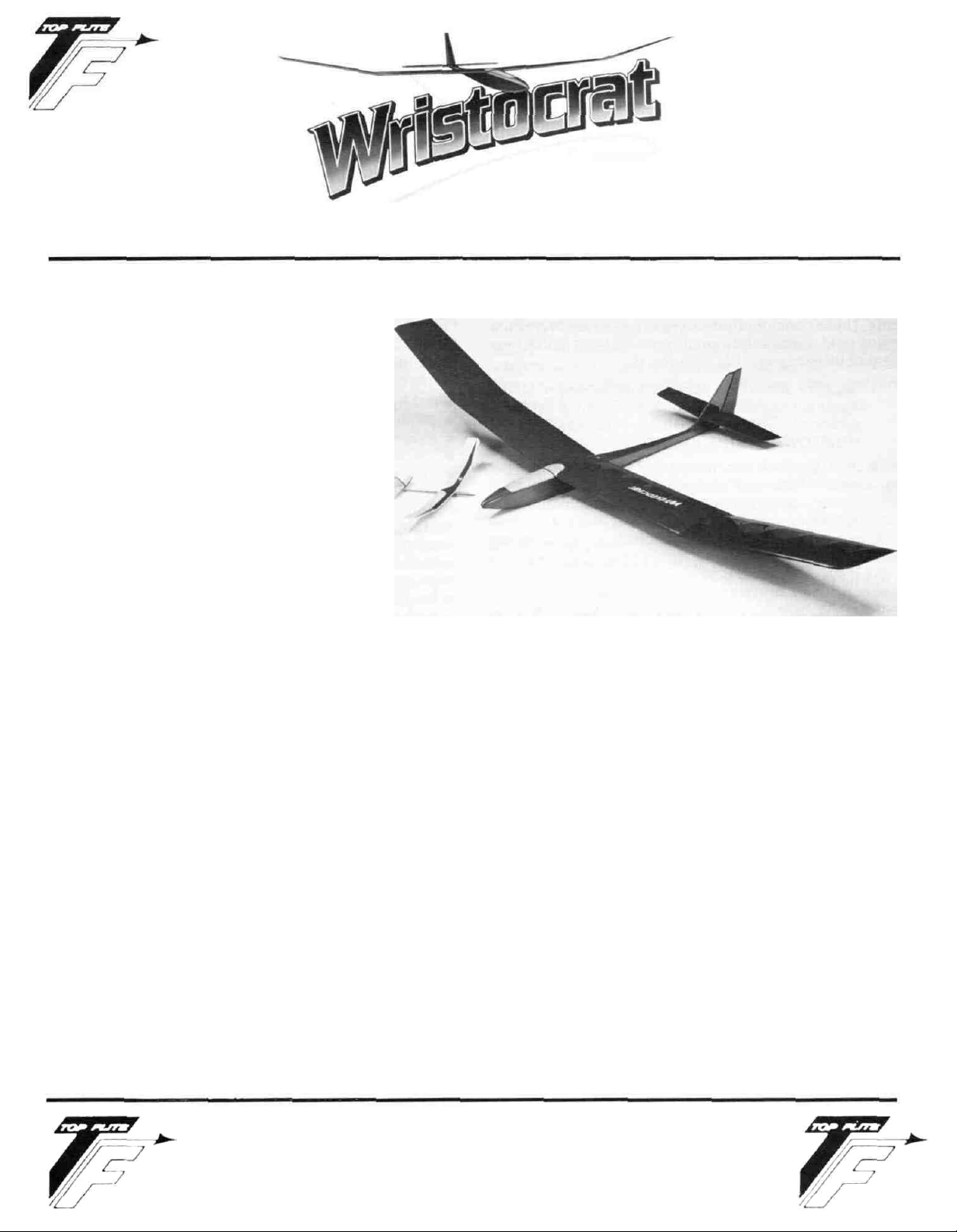
We believe the Wristocrat to be one of the
best hand-launched sailplane designs
available today and certainly one of the
most complete kits of its kind. With 335
sq. in. of wing and a subsequent low wing
loading, it will work the lightest of lift.
With practice, realistic launch heights of
35 to 45 feet can be achieved by persons of
average build, resulting in "dead air" (no
lift) times of 40 to 60 seconds per launch.
By learning to launch your Wristocrat over
lift generators, such as baseball dia-
monds, tennis courts, etc.... (patches of
land with dark, contrasting topography),
experience the thrill of hooking and riding your first lowlevel thermal.
The Wristocrat isn't just a thermal ship, you'll find it
excellent on the slope as well. It's aerobatic and the
airfoil allows it to be flown in a fair wind. Installation of
the optional towhook allows the use of small hi-starts
for even greater heights on flat land. It's a versatile
model and a lot of fun on trips such as vacations.
You'll note on the plans that we've even shown a flap
option. This additional control function is easy to build
and makes your Wristocrat even more versatile in the
performance department! This simple option is
explained well in this manual and on the plans, give it
some consideration.
Choose your radio system carefully for
there are several factors to address; size, weight, etc. As
shown, our prototypes are being flown with Airtronics
#501 servos, standard six-channel receivers and SR 300
Mah battery packs of either square or flat configuration.
There are several systems that will also work; Futaba,
your Wristocral,
you
can
Cannon, Tower "Mini Flight Pack", etc. We do urge you
to have the radio system that you plan to use available to
you before you start construction.
Build your Wristocrat to the plans and instructions
provided and you are going to have a strong, light model
that is up to the task it was designed for.
Included in this kit is a 1/4" scale model of the same
airplane, the Wristocrat II. This model, when built
properly, can provide your children or grandchildren
with hours of enjoyment and help them to understand
some of the simple laws of aerodynamics that apply to
models as well as full-size aircraft. We urge you to take
the time to work with that special child in your life on this
project and to take them with you when you fly your
Wristocrat. We believe that you'll be amply rewarded with
not only the flight characteristics of this small model,
but also with the time spent together. While the
instructions provided with the Wristocrat II are simple,
your own special input to your child can be an
experience that will be long remembered. Sharing the
wonders of model aviation with a child is its own reward.
TOP FLITE MODELS INC.
1901 NORTH NARRAGANSETT AVENUE • CHICAGO. ILLINOIS 60639
Page 2

IMPORTANT NOTE:
TOP FLITE MODELS, INC. certainly recommends the
Wristocrat as a first R/C aircraft. However, if you are a
beginner to the sport of
seek and use experienced assistance in constructing
and flying this airplane. Again, if you are new to this hobby, consider this:
Flying this or any other radio-control led model aircraft is
a PRIVILEGE and not a RIGHT and this privilege begins
with the utmost safety considerations to others and
yourself as well. An R/C model airplane in inexperienced
hands has the potential of doing serious personal or pro-
perty damage. These safety considerations start at the
building board by following instructions, seeking com-
petent help when you are confused and avoiding shortcuts. These considerations have to be carried over to the
flying field where safety must come first and limitations
cannot be exceeded. We urge you to:
D 1. Send for and obtain your AMA (Academy of Model
Aeronautics) membership which will provide insurance for your R/C activities — DO NOT RELY ON
HOMEOWNERS INSURANCE.
D 2. Join an AMA sanctioned R/C flying club in your
area where you can obtain competent, professional instruction in trimming and learning how to
fly this model.
Check with your favorite local hobby shop for the
required AMA forms or the address where they can
be obtained.
A radio controlled model is not a "toy." Care and
caution must be taken in properly building the
model, as well as in the installation and use of the
radio control device. It is important to follow all
directions as to the construction of this kit as well
as installation and use of the engine and radio
gear. The advice and assistance of a well experienced builder and pilot is highly recommended. Don't take chances! Improper building, operation, or flying of this model could result in serious
bodily injury to others, yourself, or property
damage.
PRE-CONSTRUCTION NOTES:
The Wristocrat, like other Top Flite kits employs the use
of die-cut wood to ease the task of construction, parts fit
and identification. The dies used for this kit have been
rigorously checked for absolute accuracy and should
provide you with excellent fit. Die-cut parts should be
carefully removed from their sheets by first lightly sanding the back of each sheet of parts and then carefully
removing each part. Use a light garnet paper for the sanding and keep a sharp hobby knife with an X-acto #11
blade or equivalent handy for assistance in removing
any parts that might not have been completely cutthrough on the dies. Parts which oppose one another
and must be precisely uniform—such as fuselage sides,
R/C
flying, we would urge you to
WARNING!!!
ribs, etc...— should be carefully "matched" after their
removal from the parts sheets. Matching is the process
of holding the opposing pieces together with either pins,
tape or spot gluing and lightly sanding the edges of the
parts until they are identical. A sanding block with light
garnet paper is most useful for this and other phases of
construction.
Your building surface should be at least large enough to
accommodate the wing panels. This surface should be
as absolutely flat as possible and yet be able to accept
pins easily. We have found that a product such as
Celotex fiber board works quite well for this purpose.
Another good surface can be found in most well-stocked
hardware stores, this is a 2' x 4' fiber board ceiling tile —
these are quite inexpensive and can be used for several
airplanes before needing replacement.
As with most R/C kits that are constructed from wood, a
selection of tools—most of which can be found in the
average workshop—are a must to do the job correctly:
• Hobby knife and sharp #11 blades
• Single-edge razor blades
• T-pins
• Sanding blocks in assorted sizes
• Sandpaper in various grits
• Hand-held hobby saw, such as an X-acto
• Dremel tool or power drill and assorted drill bits
• Straight-edge, preferably metal, at least 36" long
• 90 degree triangle
• Soldering iron, flux (silver) and solder
• Carbide cut-off wheel for wire cutting
• Small power jig-saw, such as a Moto-Saw
• Razor plane
• Tapes such as masking and cellophane
Our Wristocrats' were constructed using a variety of com-
mon hobby adhesives including 5-minute epoxy and
Cyanoacrylates. Since all of us have our own construction techniques and favorite adhesives, stick with the
ones that you are familar with and prefer. However, in
certain areas there will be callouts for certain types of
adhesives and we urge you to try not to substitute since
doing so could possibly cause problems structurally
later on.
The last thing we should touch on before we begin actual construction is the sequence in which the Wristocrat
is assembled. The sequence given to you in this booklet
has been proven to be the most straight-forward and provides the finished components in the order that you will
need them to progress to the next assembly phase. Try to
stick with the building order presented here to avoid
mistakes.
Spread the plans out on your work surface, cover them
with a clear plastic material, such as the backing from a
roll of Monokite or plastic food wrap an commence construction.
FLAP OPTION
This is the point that you must make up your mind about
the installation of flaps or whether you are going to use
your Wristocrat as a purely 2-channel sailplane. If you
want the flaps then you should take the time to study the
plans to see how we've accomplished this mechanism
2
Page 3

with our prototype machines. Essentially, the flaps
themselves are nothing more than the hinging and
subsequent control led movement of the 1" trail ing edge
stock itself. As shown, the flap extends from the polyhedral break, inboard to the point shown on the plans,
next to the fuselage. You will need to pick yourself up
some Sullivan #507 cable and tube material (one
package is all that's needed) from your local hobby
shop. The rest of the items needed are either in the kit
itself as scrap and /or common household items.
The need to understand the drawings provided is essential — study them. The flaps are hinged from the bottom
and driven by cable through the top of the wing. At the
exit point for each of the cable housing tubes you will
need to replace the stock balsa cap strip with a wider
one (about 1/4" - 5/16" will do ) to anchor the tubing. Also,
each wing rib end must be trimmed 1/16" cap that is glued
in place instead of the trailing edge stock itself. Note
that we've also added 1/16 x 1/2" balsa sheet, top and bottom, to each inboard wing panel, at the trailing edge for
strength and to facilitate covering The flap control
horns were made and mounted in the same manner as
was the rudder horn, and the connectors are also made
from a common paperclip, as was the rudder connector.
The flap system is driven by a single servo that is
mounted, as shown, in the wing's center section. This
servo protrudes down into the fuselage itself and is con-
nected to the receiver's "throttle" connection.
Therefore, on a typical Mode II transmitter, where
aileron (rudder) and elevator are on the right stick and
throttle is on the left, the positionable throttle stick
becomes your control over the flaps. Our prototypes
have been set-up so that "full throttle" (stick all the way
up) and full down trim is "neutral" flap— in other words,
no flap, up or down, what-so-ever. Therefore, by moving
the throttle stick downward, the flaps come down also,
to whatever desired location. Moving the stick back up
to "full throttle" moves the flaps back to neutral. The
flaps can also be "reflexed" or moved upward forgetting
quickly through "sink" or down air or for compensating
for high winds, by moving the throttle trim lever upward
to whatever desired position. On our Airtronics equipment, we typically can achieve about 6 to 8 degrees of
reflex, which is more than sufficient to make our
Wristocrats really scoot!! Honestly, you can't begin to appreciate what an incredibly useful tool this system is until you've tried it.
As you can see, the flap servo, at least in our prototypes,
is mounted in the wing's center section, with the output
arm literally inside the structure. This means that the
two center ribs,W-1, must be cleared out, at this point, to
allow the servo to be mounted in place. The best time to
do this is after the two inboard wing panels have been
glued together and before the top, rear center section
sheeting is installed. In fact, it is at this point that the en-
tire system is installed, tubing, cables, etc... Note that
the drive system in the wing's center section is essentially a "blind mount". This means that all of the connections inside of the center section must be fitted to the
servo's output arm before covering it up with the top
sheeting. Afterfitting and making sure that the servo, by
radio command, does indeed actuate the cables in the
correct direction, with no binding, and that the geometry
is correct, then and only then can the servo be removed
from the wing and construction proceed. Later, after
covering, the servo is carefully installed, screwed in
place and the last connections are made to the flaps
themselves.
There are no guarantees that your particular radio
system will work this option and you therefore need to
determine this for yourself by first making sure that the
shape and dimensions of the servo you plan to use will
indeed fit as shown. Then you need to find out if your
radio system has the capability of offering you "reflex"
flap off of the throttle trim lever (some systems don't).
Our opinion is that even if you can't get flap reflex, due to
the type of radio you have, the flap option itself is still
worth the extra bit of work.
With the proceeding information still fresh in your mind,
we'll now move to the wing construction sequence of
this manual. The following assumes that you are
building the stock, non-flapped wing.
WING CONSTRUCTION
Be sure and protect your plans by covering them with
backing from a roll of Monokote™ or a material such as
clear food wrapping. Take a minute to study the plans
and understand them. We suggest building a right and
left wing panel, starting with the inboard sections first
and then joining these two completed structures at the
appropriate time in the building sequence. We'll start
with the left wing first. If you're planning on the flapped
version, it is at this point that you'll start adding the
structures shown (dashed lines) on the plans.
D
1. From the
cut, fit and locate over the plans, the bottom
leading edge sheet (use a long straight edge to
develop the correct width and to true-up the
edges). From the 1/8" x 1/16" spruce spar stock provided, measure and cut the required 15" length for the
bottom spar, set this aside for a moment. Now cut
and locate over the plans, the 11/4" x 1" length of
shaped trailing edge stock. Now cut and glue the
bottom center section sheeting in place tothetrailing edge stock and the forward bottom wing sheet.
Cut, fit and glue in place the six bottom 1/16" x 3/16"
cap strips from the stock provided. Using one of
the die-cut W-2 wing ribs as a location guide, the
bottom spruce spar (cut earlier) can now be glued
in place. Lastly, note in the cross sections that the
leading edge of the bottom wing sheeting needs to
be lifted up and supported in order to match the
bottom contours of the wing ribs, forward of the
spar. This is best done with a length of trailing edge
stock.
D 2. Note that we've provided you with "tick" marks
just infrontof and just behindthewing paneldrawings. These correspond with the rib locations. Use
a straight edge and a soft lead pencil to now mark
the rib locations directly on the leading edge and
center section sheeting. The first wing rib to be installed is the first W-2 rib, inboard from the polyhedral break (the inboard end of polyhedral brace
1/16"x
3" x 30" sheeting provided in your
kit,
3
Page 4

W-10 will butt against this rib when it is installed).
Continuing to work inboard, toward the center, install the next three W-2 ribs. From their die-cut
sheets, remove ply dihedral braces W-8 and W-9
and polyhedral braces W-10 (balsa). The two remaining inboard W-2 ribs must now be cut to compensate for the installation of the W-8 and W-9
dihedral braces; use these braces as a thickness
guide and trim the ribs as shown on the plans.
Finally, root rib W-1 must also be trimmed into two
pieces also to fit in front of and behind the dihedral
braces. Once this is done, again use W-8 as a
guide, by holding it in place, and glue all of the re-
maining forward rib ends in place to the bottom
leading edge sheeting; remove W-8 from the structure. Using W-9 as a guide, glue all remaining rear
rib ends in place and remove W-9 from the structure. The remaining outboard W-2 rib must be trimmed in a similar manner since it is intersected by
polyhedral brace W-10. Using the same procedure
as described, trim this rib into a front and rear piece
and glue in place using W-10 as a spacer; remove
W-10 from the structure.
D 3. Cut, fit and glue the 1/4" sq. leading edge in place.
D 4. Carefully remove this structure from your work sur-
face. Use a sanding block to lightly sand the out-
board edges (the polyhedral break) smooth. Place
the structure back on the plans and block up the
center
2-11/2".
Using the same construction as
described earlier, the outer wing panel is now built
directly over the plans and directly to the inner
panel. Take pains to bevel the trailing edge butt
joint for a good fit. Be sure to install W-10 first
before the front and rear segments of W-2, followed
by W-3, W-4, etc.
D 5. With all of the ribs in place, cut, fit and glue the top
spruce spar in place from W-7 to the W-2 at the
polyhedral break. From your parts bag, locate the
bundle (10 provided) of vertical grain shear webs.
Carefully trim one of these to fit precisely between
W-3 and W-2 and against the spars and W-10 with
the top flush with the top of the
spar. Once
satisfied, glue this web in place.
D 6. As shown on the plans, the 1/4" sq. leading edge
must now be sanded down to match the top contours of the ribs. The judicious use of a razor blade
followed by using your sanding block to finish the
job is the way to go here. Once you're satisfied you
can cut, fit and glue in place the top 1/16" leading
edge sheeting (note that this top sheeting is plac-
ed slightly forward on the top spar thus creating a
bit of a "shelf"). Lastly, cut, fit and glue in place all
of the top 1/16" x 3/16" cap strips with the exception of
the one which will cover the W-2 ribs at the
polyhedral break. Remove the thus far completed
left wing panel from your work surface. Use your
sanding block to smooth the outboard face of W-7
in preparation for the wingtip. Inspect the bottom
polyhedral joint and lightly sand as needed to
smooth it out.
D 7. The right wing structure is now built using the
same procedures just described.
D 8. In this step, we're going to join the right and left
wing halves together. Preparation for this requires that the two inboard ends of the wing
halves be sanded smooth and beveled to create a
good, straight fit. Do this now. Pin or weight one
of the wing halves (let's use the left) flat to your
work surface. Next, make sure the rib curve in the
bottom leading edge sheeting is supported with a
length of trailing edge stock. With everything
secure, trial-fit the right wing half in place with
it's polyhedral break supported
2-5/8"
off of the
work surface. The resulting butt joint should be
as flush fitting as possible and the leading and
trailing edges of both inner panels should be
straight; take your time here and ensure that the
fit is the best you can produce, with all parts
lining-up correctly. Once satisfied, apply a thin,
even coat of glue (5-minute epoxy is great here) to
the inboard end of the right wing panel and
carefully fit it to the pinned down left panel, again
making sure the right panel is raised
2-5/8"
polyhedral break. Carefully wipe off any oozing
adhesive. Now fit W-8 dihedral brace in place,
trimming if needed for a good fit. Glue W-8 in
place. Cut, fit and glue the left panel's spruce
spar in place. Rear dihedral brace W-9 can now be
glued in place.
D 9. With the left wing still down flat to your work sur-
face, locate the vertical grain shear webs
balsa). Cut, fit and glue these in place between
the remaining W-2 ribs, out to the polyhedral
break.
D 10.
Remove the joined wing structure from the
bench. Pin or weight the right panel in place to the
bench and glue the remaining top spruce spar in
place followed by the remaining vertical grain
shear webs.
D 11.
As you did with the tip panels, carefully shave and
sand the inner panel's leading edges to conform
with the top contours of the wing ribs. Use your
sanding block to lightly sand any high points on
the panel's top surfaces. Once you're satisfied
that the inner panels are ready to sheet, pin or
weight one side or the other in place on your work
surface. Cut, fit and glue the leading edge
sheeting in place (again leaving a bit of a "shelf"
at the rear edge of the top spar). Cut, fit and glue
the center section sheeting in place using the
patterns shown on the plans. Finally, add all of
the remaining 1/16" x 3/16" cap strips out to and including the polyhedral break. Repeat this procedure on the opposite wing panel.
D 12. Locate and remove wingtip parts W-11 from their
die-cut sheets. Sand their inner edges lightly to
render them flat and straight. Note the tip reinforcement option shown on the plans. This addition of a length of
1/8" x3/16"
spar stock really
serves
to "beef-up" an otherwise accident prone area,
you might give it serious consideration. Glue the
W-11 wingtips in place as shown on the plans
("End View of Wingtip", left panel). Also as
shown, cut a few scraps of 1/8" balsa to fill in the
4
at the
(1/16"
Page 5

leading edge of the wingtip and glue these in
place. From the remaining 1/16" balsa sheet provided in your kit, cut, fit and glue in place the wing tip
braces as shown on the plans. You may elect to
add these only to the top, which will work.
However, on our prototypes we added these
braces top and bottom and have yet to break a tip.
D
2. Glue two of the S-2 caps to the bottom of each S-1,
carefully lining-up their edges one to the other.
Use sandpaper to lightly rough-up the two
1-1/4"
lengths of aluminum tubing. Place the two S-1/S-2
structures together on your building board with
their inboard edges touching and the slots lined
up. Glue the two lengths of aluminum tubing in
place in the slots being careful to keep glue out of
the tube ends. Wipe off any excess glue that may
ooze up. Now glue the two remaining S-2 parts to
the tops of the S-1's, aligning their edges, weight
to keep these flat and allow to dry. If you're using
Pacer Slo-Zap, this will be very fast. Cut the two
structures apart, at the center, using a sharp razor
blade or a fine-toothed X-acto-type saw. Clean-up
the ends of the aluminum tubing with your #11
blade. Holding the two structures together, one
on top of the other, use your sanding block to
sand each of the edges flat.
.1/8" BALSA FILL
TOP AND BOTTOM
The completed wing structure should now be carefully
sanded to final shape including the leading edges. Make
every attempt to render the wing as smooth and as
uniform as possible.
Ply die-cut part F-12, wing bolt reinforcement, can now
be glued in place on the wing's center section at the trail-
ing edge, as shown. With the exception of the front and
rear fuselage/wing fairings, the wing should now be
complete.
STABILIZERS/RUDDER CONSTRUCTION
STABILIZERS
D 1. Remove the four 1/32" S-2's and both of the 3/32" S-1's
from their respective die-cut sheets. These are
the stab cores (S-1's) and stab core caps (S-2's).
From your parts bag, locate the single 3" length of
1/16" I.D. aluminum tubing. Measure and cut-off
two,
1-1/4"
lengths of this tubing. Use a single edge
razor blade and a rolling motion on a hard surface
to do this. Save the remaining 1/2" length. Note the
cross-grain marks in the S-1 cores, these are the
locations for two lengths of aluminum tubing that
you just cut. Use a straight edge and a sharp #11
blade to clear-out a 3/32" slot at these marks to
allow the nesting of the two pieces of tubing. Take
care in cutting these slots to maintain their
parallelism.
D
3.
Locate
the two
1/16"
dia.
x1-1/2"
steel
pins
from your
parts bag. Clean the ends of each of these with a
grinder or carbide cut-off wheel and trial-fit them
into the aluminum tube nests in each of the stab
core assemblies. You should be able to lay this
joined assembly directly over the stab plans and
they should match accurately. Trim as needed to
achieve this. Once satisfied, weight or pin the
wire-joined core assemblies in place over your
plans (protect the plans with a piece of Monokote
backing) and build the balance of each stab half
onto each stab core assembly using the 3/16" sq.
and
3/32"
x3/16"
balsa stock provided.
D 4. Once the stab halves are finished, remove them
from your work surface and use your sanding
block to first sand the top and bottom surfaces of
each flat and then to carefully "airfoil" them to
the cross-sections shown on the plans. Use care
to not sand these structures to thin, we don't
want them weak. Set these assemblies aside for
now.
RUDDER
D 1. The rudder is built directly over the plans, using
the
3/16"
sq. and
3/32" x 3/16"
balsa
stock
provided,
just
as the stab halves were.
D 2. Remove the completed rudder from your work
surface and use your sanding block to smooth
the sides as well as the edges. As shown on the
plans, the top, leading edge and bottom of the
rudder, on each side, is capped with 1/32" x V
balsa strips, cut from the RC-35-5 die-cut sheet.
This renders the rudder the same thickness as the
fin.
The final sanding of the rudder and the beveling of its
leading edge, for hinging purposes, will be done later in
Final Assembly.
FUSELAGE/FIN CONSTRUCTION
Note that the fuselage and fin, with it's stabilizer drive,
are constructed in the following set of instructions, as a
finished, single unit.
5
Page 6

D 1. Remove the two fuselage sides from their die-cut
sheet. Tape, pin or clamp them
together
and use a
sanding block to lightly sand their edges, thus
matching them exactly. Now lay one of the
fuselage sides directly over the side view on the
plans and accurately mark the location of the F-3
lite-ply former. Also mark the location of the end
of the top 1/8" sq. balsa longeron at the leading
edge of the fin — this will be at an angle, use a
straight edge. Lastly, mark the location of the forward end of the bottom 1/8" sq. longeron, where it
butts against the noseblock. Duplicate these
marks on the remaining fuselage side —
remember that you need a right and a left
fuselage side!
D 2. Glue the two F-2 balsa doublers in place on the in-
side faces of each fuselage side, matching its top
contours to those of the fuselage sides. Glue the
top and bottom 1/8" sq. balsa longerons in place
after first trimming their ends to fit the marks
made earlier. Remove the fuselage sides from
your work surface and pin, tape or clamp them
together again. Use your sanding block to once
again make sure they are identical. While they're
together, check the trimmed ends of each
longeron to be sure they are matched accurately.
Set these aside for now.
D 3. Using the 3/16" sq. and 3/32" x 3/16" balsa stock provid-
ed, build the fin frame directly over the plans.
Take your time and ensure that each of the required joints is accurate and well-matched.
Remove the frame from your work surface and
use a sanding block to lightly smooth out the
sides and edges. Remove one of the T-1 fin sheets
from its die-cut sheet. This can now be glued in
place to the right side of the fin frame, as shown
on the plans. Do this operation accurately and
with a minimum amount of glue.
D 4. The right side of the fin frame, outer 3/16 "edges on-
ly, is now capped with 1/32 " x 3/16" strips cut from the
open, center area of die-cut sheet #RC-35-5. This
carries through the increased thickness of the fin
created by the T-1 fin sheet. Note the "+" mark
toward the rear of the T-1 fin sheet. Use a 3/32 "drill
to accurately make a hole at this mark. This hole is
referred to as the stab pivot hole. As shown on the
plans, glue a short length (about V will do) of 3/16"
balsa stock directly over the 3/32" dia. hole just drilled through T-1.
D 5. Take the right fuselage side and pin or weight it in
place carefully over the plan. Place the fin
assembly on the fuselage side, at the rear to check
its fit and trim carefully, if needed. Place a scrap
piece of 3/32" stock underneath the fin frame, above
the fuselage side, to bring the fin level. Carefully
glue the fin frame assembly to the fuselage sidepin or weight in place and allow to dry.
D 6. From your kit box locate and remove one of the
braided metal drive cables and one of the outer
cable housing tubes. Use a piece of sandpaper to
lightly scuff the outer surface of the plastic tube.
As shown on the plans, the stabilizer cable drive
tube is going to be glued directly to the right
fuselage side and up into the lower fin, directly
beneath the oval stab drive hole in T-1. Position the
forward end of the stab drive tube just ahead of the
F-3 former location and glue it in place to the right
fuselage side, just beneath the F-2 doubler and
about 1-1/2" back from the F-3 location. (An
adhesive such as Pacer's Slo-Zap CA is great for
this operation.) Repeat this procedure all the way
back to just beneath the fin, noting that the stab
drive tube gently arcs down to the fuselage bottom
as
it is positioned rearward. Before making the
bend up to the oval hole in T-1, load the tube with
the inner braided cable. Now make the bend up to
the hole and hold this assembly in position. Try
moving the cable back and forth; it should move
easily without binding. Once satisfied, glue the
short length of 3/16" sq. balsa in place as shown to
hold the tube and then glue the tube to this block.
Use a razor blade to trim off the tube end after removing the cable.
1/32" X 3/16" BALSA
LAMINATED EACH SIDE
OF FRAME
CABLE GLUED TO
BALSA BLOCK
1/16"
I.D.
ALUMINUM
TUBE
6
BRASS TUBE
FLATTEN END THEN DRILL
1/16" DIA. HOLE
STABILIZER CONTROL CABLE.
SOLDER INTO BRASS TUBE
Page 7

D 7. As shown on the plans, the stab drive fitting itself
is nothing more than a short length of 1/16" I-D.
brass
tubing
(11/2"
provided) which has about
1/8"
of
it's length flattened in a vise. This "flat" is then
drilled with a 1/16" dia. hole. The other end of this
tube is trimmed in length to leave only about 1/8"
left that is still "tube". This fitting is then soldered
to the end of the stab drive cable. Do all of this now.
Handy Hint: Insert one of the 1/16" dia. M.W.
stabilizer pins provided, into this piece of tubing,
almost to the end and then flatten the tubing in a
vise. The music wire pin will keep the tubing round.
D 8. Now install the rudder drive tubing on the left
fuselage side. As shown, this tubing exits the
lower rear of the fuselage side through a heavily
angled hole that must be drilled. A sharpened
piece of tubing will work well for this step. Like the
elevator tubing, the rudder housing tube is glued in
place along the fuselage side at
1-1/2"
intervals.
Use a razor blade and then your sanding block to
smooth the area of tubing exit on the outside of the
fuselage. Don't worry about the stab and rudder
tubing that is loose up front, we'll nail these down
later.
D 9. Now glue the remaining T-1 fin side in place on the
left side of the fin, with the stab drive cable and fitting in place. Glue 1/32 " 3/16"" caps on the left side of
the fin frame, just as you did on the right. Use your
sanding block to smooth this structure. Now trialfit the left fuselage side to the right, paying particular attention to the fit of the fin. This should be
accurate and close-fitting. Once satisfied, the left
fuselage side can be glued in place to the fin and
right side—the glue joints should be at the top and
bottom longerons 1/2" ahead of the fin's leading
edge back to and including the left T-1 fin side. Accurately match the fuselage sides, weight and/or
pin this structure to your work surface and allow to
dry.
D 10. Ply fuselage former F-3 should now be trial-fitted
in place (just move the loose ends of the rudder
and stab tubes out of the way). Make sure this
former fits well, trim if necessary. Take one of the
servos that you plan to use and hold it in place on
the inside of the fuselage, about where it will be
mounted. Note the location for the two drive tubes
on F-3 (these should be lined-up with the servo's
output arm. Remove F-3 and either drill a hole or
slot the former to accept the two tubes. You now
can glue F-3 in position at the marks made earlier
on each of the fuselage sides. We suggest using
something like 5-minute epoxy for this operation
since you may need a moment or two for position-
ing. We also suggest that you accurately position
the entire structure over top view on the plans and
use weights or pins to ensure that the whole thing
is kept straight!
D 11. Trial-fit the balsa nose block in place and pinch the
fuselage sides together as if you were gluing it in
place. How does it fit? Everything square as it
ought to be? When viewing the structure head-on,
is it straight? If the answer is no to any of these
questions, take the time now to trim the ends of
the longerons and/or the F-2 doublers to correct
the problem. Once satisfied, glue the nose block in
place and clamp or tape the fuselage sides
together at the nose until dry. When it is, use your
sanding block again to smooth out the
fuselage/nose block fit, top and bottom.
NOSE BLOCK
D 12. Locate the 1/8" ply wing-bolt plate from your parts
bag. Trial-fit this part in place at the location
shown on the plans (beneath the wing's trailing
edge). Trim if needed. Once satisified, glue this
plate in place against each fuselage side and up
against the bottom of the F-2 doublers. Locate and
remove the die-cut F-5 fingerhole reinforcement
piece. Trial-fit F-5 in place flush with the bottom
fuselage longerons and directly beneath the 1/8"
ply bolt plate just installed. Once satisfied with the
fit, glue F-5 in place, between the bottom
longerons and flush with the fuselage sides. Now
cut a 1-3/8" length of
1/16"
x 3/16" spruce spar stock. As
shown on the plans, this part is now glued in place
on top of F-5, between the fuselage sides, at the
forward edge of the fingerhole cut-out. This part
serves to reinforce F-5 against undue wear during
repeated hand-launches. Lastly, cut and glue the
1/8" x 3/16" balsa cross brace in place. As shown on
the plans, this brace fits between the bottom
fuselage longerons, just behind the receiver location. Use your sanding block to now lightly smooth
the fuselage bottom prior to sheeting.
7
Page 8

D 13. Remove ply die-cut part F-6 from its sheet. This is
the forward, bottom fuselage sheet which is
meant to fit from the cross brace just installed, forward to the noseblock. Clean-up its edges with a
sanding block. F-6 can now be glued in place using
weights or tape to hold it (note that its rear edge is
glued halfway across the width of the cross brace;
use a scrap piece of balsa to clean out any oozing
glue from beneath this edge). Using the 1/16" x 3"
balsa sheet stock provided, finish sheeting the
fuselage bottom from the rear edge of F-6, aft to
the end of the fuselage - as shown this sheeting is
applied cross grained. Once the sheeting is in
place and dry, use your sanding block to smooth
all of the edges (balsa sheeting and F-6) flush with
the fuselage sides. Now clear out the finger hole
described by F-5, using sandpaper to smooth the
edges. The last thing you may wish to do on the
bottom of the fuselage is to drill a hole, back
toward the leading edge of the fin location, to provide an exit for your antenna. On our prototypes we
angled this hole forward and lined it with a short
length of plastic tubing.
D 14. Now trial fit your wing to the fuselage. Make sure
the wing is centered and that the leading edge is
up against F-3. Holding these two structures
together, observe the fit between the bottom of the
wing and the wing saddle area. It may be
necessary to slightly bevel the tops of the fuselage
sides and F-2 doublers to get a snug fit; do this
now. Once you're satisfied with the wing/fuselage
fit, you're ready make the hold-down system.
Again place the wing on the fuselage and use
weights to hold it firmly in
position. Make sure that
the wing is squarely in position on the fuselage by
taking wingtip-to-tailpost measurements as
shown in the diagram ("X" should equal "X").
Locate the 3/16" dia. dowel from the parts bag. A
3/16" dia. hole must now be drilled through F-3 (see
mark) and into the wing's center W-1 ribs, to a
depth
of
1-7/16",
F-3.
Measure this depth on
measured from the front face of
your
drill
bit and note
with a strip of tape. Once the hole is drilled, remove
DISTANCES "X" and "X"
MUST BE EQUAL
the wing from the fuselage and trial-fit the 3/16" dia.
dowel in place. Use sandpaper to slightly round
the front edge of the dowel. Now glue the dowel in
place in the wing (clean-off any oozing glue). Once
dry, again fit the wing to the fuselage and use
weights to hold it in place, as before. The rear
nylon bolt hold down system is now made. Start by
drilling a hole, with a #29 drill bit, through the
wing's trailing edge and through the 1/8" ply wing
bolt plate at a slightly forward angle (see plans).
Remove the wing from the fuselage. Enlarge the
hole in the wing's trailing edge to allow the 8-32
nylon bolt to slip through to the head. Now using
either an #8-32 tap or an 8-32 bolt (metal), tap the
threads into the hole made in the ply wing bolt
plate. Once the threads have been cut we suggest
giving them a very thin coat of instant CA glue and
again running the tap through them. This
toughens the threads in the plywood. Re-fit the
wing to the fuselage and bolt it in place to again
check the fit. Note that about 7/8" of the length of
the nylon bolt (1-1/2" supplied) can be trimmed off.
Remove the wing from the fuselage.
D 15. Use a flat sanding block and light sandpaper to
carefully sand the top of the fuselage, from F-3 forward across the top of the noseblock. Use care
here as we want the forward hatch to fit nicely.
From your parts, locate and remove the 3/8" x 2" x
10" length of balsa. Again using your sanding
block, bevel-sand one end of this block to fit
perfectly against the forward face of F-3 when held
in place on top of the fuselage. As shown on the
plans, the forward end of the radio hatch is now cut
at the angle shown. Once the bevel cut has been
made, use the sanding block to lightly clean-up
each end of the cut, set aside the hatch part for a
moment. On the remaining length of block,
measure about
1-3/4"
forward from the bevel cut
and cut this piece off. This piece then becomes the
forward "lip" for the radio hatch. Use tape to hold
the radio hatch in place to the top of the fuselage,
it
against F-3. Apply a small amount of glue to the
bottom of the forward block and glue it in place to
the top of the fuselage and noseblock, matching
the bevel on the front of the radio hatch block, thus
ensuring a nice fit between these two blocks. Un-
tape and remove the radio hatch block. Locate and
remove the ply F-4 hatch "lip" from its die-cut
sheet. F-4 can now be glued to the forward, bottom
surface of the hatch block with 3/16" of its forward
end protruding, thus providing a fit beneath the
forward block just installed and preventing shif-
ting from side-to-side. As shown on the plans, the
rear face of the radio hatch block will need a slight
amount of routing out to allow the wing's holddown dowel to clear; do this now. Once satisfied
use a couple drops of glue to lightly tack-glue the
radio hatch in place for shaping.
D 16. Remember that V length of 1/16" I.D. aluminum
tubing that you were asked to save back when you
built your stabs? Locate it now, we're going to use
it. With a 3/32" drill bit, finish the hole through the fin
(the stab pivot hole). Cut a 1/4" length of aluminum
8
Page 9

tubing, clean each end with a #11 blade and carefully insert it into the stab pivot hole just cleared
out, do not glue Now assemble the wing to the
fuselage followed by attaching the stabilizer
halves to the fin, just press in place for now What
we're going to check for now is alignment We
want to view the airplane head-on at a bit of a
distance Place it on a table, facing you, and backoff a few paces, sighting directly at the front Is the
wing sitting properly on the fuselage? Are the
stabs tilted in relationship to the wing/fuselage or
do they look "right"? If everything seems to lineup, we can proceed to finish sheeting the top, rear
of the fuselage If it doesn't, we need to know
which way to twist the fin to make everything lineup properly because once the top rear sheeting is
installed, it "locks" the fuselage firmly in place
thus making any such corrections extremely difficult, if not impossible.
If the alignment appears to be OK, remove the stab
halves, leave the wing in place and carefully cut
and glue the 1/16" balsa sheet (applied crossgrain,
as shown) top, rear decking in place back to the
leading edge of the fin However, if some align-
ment is needed by having to pull the top of the fin
left or right, now is the time to do it, before apply-
ing the
the assembled airplane on a large, flat table Place
weights (magazines, lead, whatever) on top of the
wing
Again sighting directly at the front of the model,
determine which way the fin has to be tilted Pull
off a long
top of the fin Pull against the tape until the fin is in
the right position and stick the other end to the
table, thus preventing the fin from shifting Once
satisified that it is now properly aligned, cut, fit
and glue the top, rear sheeting in place as earlier
described Let the sheeting dry before removing
the masking tape from the fin and you'll find that
the fin is now properly aligned Disassemble the
wing and stabilizer halves from the fuselage Use
your sanding block to now sand the top, rear
sheeting and the forward radio hatch and nose
block piece flush with the fuselage sides You can
also now sand the top forward hatch and nose-
block contours to shape as shown on the plans, no
need to round corners yet.
top, rear sheeting This is how it's done
center section,
length of masking
thus
holding
it firmly in place.
tape and stick
it to the
Set
FINAL ASSEMBLY
Its often been said that the difference between a good
model and a great one is sandpaper and the willingness
and ability to use it This is the point in construction that
can literally make or break the performance and the look
of your model Since the WRISTOCRAT is an obvious
candidate for use of Monokote™, you would do well to
keep in mind that the surface preparation of the wood
will dictate the finished, covered look of your model
When we reference the use of "filler" in the following
text, we have found that some of the best products to
use are those such as "MicroFill" or Model Magic Filler
or something similar These products dry quickly, are
very light and Monokote goes over them nicely. Look for
these at your local retailer
Let's start with the fuselage since the other components
should, by now, be sanded and about ready to use
D 1. Note the lower left corner of Cross Section C-C on
the plans This demonstrates about the correct
amount of radius that can be and should be sanded into the fuselage bottom As this sanding
radius moves aft, toward the fin post and the
fuselage diminishes in width, the result will be
pleasant looking oval shape Next, sand the radio
hatch and nose block sections to a nice, rounded
look right down
paper at first, followed by something like #220 will
do the job nicely The last section to tackle is the
top, rear of the fuselage, back to and including the
fin fairing and fin leading edge Take every effort
needed to sand this structure to the point that it
looks and feels like one piece You will note that
where the T-1 fin sides meet the fuselage sides,
there is a disparity in wood thickness, resulting in
a kind of "lip" On our prototypes, we handled this
by sticking a length of masking tape, lengthwise,
about 3/16" above this joint, on
ly sanded down the fuselage side(s) to as close to
T-1 as possible (the masking tape was there to protect T-1 in case we got too close) Then with the
tape still in place, we used filler to "fair-in" this
joint, feathering the material carefully When the
filler was dry, the tape was removed and we used
very light sandpaper to finish feathering the joint.
to
the nose Using a rougher grit
T-1
Then we careful-
of
D 17. From your parts bag, locate the 1/4" shaped
fin/fuselage fairing Use your sanding block to ad-
just the angles if needed and glue in place As
shown, this is now trimmed to fair the fin leading
edge into the top, rear of the fuselage
Finally, push the 1/4" length of aluminum tubing
that's in the rear pivot hole about halfway out, apply just a bit of adhesive to its outer surface
(5-minute epoxy or slow cure CA) and push it back
in place in the fin.
With the exception or contouring and final sanding, your fuselage should be complete
9
Page 10

Use your sanding block to sand the trailing edge of
the fin flat and straight.
The last step in preparing the fuselage for covering
is to sand the fin/rudder combination together, as
a single unit Start by using masking tape to accurately position the rudder to the fin — tape on
the sides only Now use your sanding block to ac-
curately match the side view shape of the rudder to
the fin/fuselage Once that's done, remove one of
the pieces of tape from one side only and lay the
structure down on a flat surface — taped side
down Use your sanding block to now sand the rudder's cross-section shape into the fin/fuselage,
but only about halfway Add another piece of tape
to the now sanded side, flip the structure over,
remove the tape and repeat the sanding operation
After a couple of passes on each side, you should
be about where you want to be, a fin with a true
leading edge and a rudderwith a true trailing edge
and everything inbetween accurately matched
The leading edge of the rudder can now be beveled
as shown on the plans, thus facilitating left and
right movement when hinged with Monokote
Once this is done, locate and remove the 1/32" ply
rudder horn from its die-cut sheet Onceagaintape
the rudder to the fin, right side only Use a sharp
#11 blade to now cut a 1/32" wide slot in the rudder's
leading edge, at the bottom, on a plane correspon-
ding to the rudder tube's exit point on the fuselage
Once the slot is made to your satisfaction, trial-fit
the horn in place and trim as needed to get a proper
fit Do not glue the horn in place until after model is
covered
D 2. Assemble the wing to the fuselage and cinch it
down with the wing bolt In this step we want to
rough cut and fit the forward and rear
wing/fuselage fairings to the wings center section The remaining length of radio hatch block
balsa will be used for this First either carve or use
a Dremel tool to route out the bottom mating surface of each of these blocks, cut and fit, cut and fit,
etc , until you have an acceptable fit Bevel the rear
block to match the fuselage (viewed from the side)
and then use your #11 blade to carve out a space
for F12 when the block is held in place Also, the
head of the bolt will indent the bottom of this block
and therefore give you the location to drill a1/4" dia
hole to allow the bolt head to seat against F12
Once you're satisfied with how the two blocks fit
to the wing and to the fuselage, concentrate on the
top view The forward block should be sanded to a
sort of half-round shape, carrying through the
shape of the hatch block The rear block gently
curves in to the center line of the wing to a point
about 2" to 2-1/2" from the trailing edge Glue the
blocks in place to the top of the wing while the
wing is still attached to the fuselage Protect the
wing sheeting around the edges of these blocks
with strips of masking tape and sand the blocks to
a final shape Use filler to fillet the blocks to the
wing, lightly sand and you're finished Remove the
wing from the fuselage
D 3. Use a sharp razor blade to now remove the finish-
ed radio hatch block With the battery/servo compartment now open, this isthetime to install your
servo mounting rails Note on the plans that
we've used the remainder of the
1/8" x 3/16"
spruce
spar stock for these You may wish to use ply In
stall these rails in the approximate positions
shown on the plans, with the servo's output arms
lined-up with the rudder and elevator tube ends
protruding through F3 Once satisfied, remove
your servos
D 4. The last suggestion that we'll make to you before
you start covering is that you take a few minutes
to "ventilate" the various structures, wing, tin
(above T-1's), stab halves and the rudder Ven
tilatmg these components allows the heated air
(formed when covering) to escape the various
sealed compartments (between rib bays, etc )
rather than expanding and "ballooning" the
covering
For the wing, we use a
3/32"
dia drill bit, hand-held,
to drill one hole through each rib, in the center,
just behind the spar location DothisfromW 7, at
the tip, all the way through the inner most W2 rib,
beneath the center section sheeting Using the
same bit, drill a hole through the bottom
sheeting, just behind the spars on each side of
the W-1's.
Use a 1/16" dia drill bit, again hand-held, to now do
the same thing to the fin( and also through the 3/16"
sq brace between the tops of the T1's), rudder
and stab halves On the rudder drill a small exit
holeon the very bottom, behind the horn location
On the stab halves, drill the exit holes through the
rear diagonal 3/16" sq piece
D 5. Final check entire airplane for any flaws or pro-
blems If you find any, fix them now
D 6. Since the stabilizer halves slip in place using two
1/16" dia steel pins, there is a need to be able to retain them This can be done a couple of ways The
first is to simply allow the pins to rust by leaving
them outdoors for a night or two This makes
them a press-fit into the stab half tubes Another
way is to use a low-tack adhesive to coat the
wires (something like 3-M #77 spray cement is
good), thus making them a bit "sticky" In any
event, don't permanently glue these in place
since eventually the need will arise for
disassembling the stab halves from the fin
COVERING
Realistically, your Wristocrat can be covered with a
single six foot roll of Monokote™ You may wish to use a
contrasting color for the radio hatch block, as we did, to
create a "canopy".
The only area of possible concern is that of covering the
stab halves and rudder These, by necessity, are thin
structures and it's conceivable that in shrinking the
Monokote, some warpage could occur To prevent this,
we've come up with a nifty little method that you might
want to try.
10
Page 11

Cover these structures just as you normally would; bottom first, followed by the tops (in the case of the stab
halves). But do not shrink the covering yet. Make sure all
of the outer framework of these pieces is adhered to with
the Monokote. Next, cut a couple of 7" - 9" lengths of
straight,
nicely. Using three
stiff
spruce stock; something like1/8"x1/4" will do
office-type
paper clamps, mount and
clamp one length of spruce on each side of the trailing
edge of the piece you're working on. The spruce won't
hurt the structure and the clamps ensure that the trailing
edge will retain it's shape. Now use your Top Flite heat
gun or iron to shrink the covering equally on both sides
(be sure the vent holes are cleared out). Let the structure
cool and then remove the clamps and spruce. You
should find that everything did indeed stay straight.
Lastly, clear out all of the required holes; rudder drive
tube, rudder horn slot, stab drive and pivot holes, etc.
Note that we've not indicated any kind of hold down
method for the radio hatch block. On our prototypes this
was not necessary because of the closeness of the fit
after covering. If yours does not fit that well, a little piece
of tape is all that's needed.
In the interest of aerodynamic efficiency, light weight
and simplicity, we strongly suggest that you hinge your
rudder (and flaps, if you have them) with Monokote as
shown in the drawings provided.
RADIO INSTALLATION
Before installing your servos, make sure that they run in
the right directions. If you have servo reversing capability, this is a simple task. Install the servos in the fuselage
on the rails provided earlier.
From your parts bag, locate
the
1-1/2"
length
of .038
I.D.
brass tubing. This material will be cut up to provide
solder connections between the drive cables and the
soft wire paper clip connectors. We recommend the use
of a good quality flux and solder when perform ing the required solder joints; Harris's Stay-Clean Flux and silver
solder are great products for this operation.
Drill a 1/32" dia. hole through the rudder horn to accept the
paper clip drive wire. Cut off about
1/4"
of the brass tubing
connector material and clean out each of it with your #11
blade to accept the cable and paper clip ends. Cut off the
required length of paper clip wire (see plans) to make the
connection to the rudder horn and bend one end into a
"Z" bend. Slip the brass connector halfway onto the
drive cable end and the paper clip wire into the other end
of this connector. Sweat solder the three pieces
together, using a minimum of solder. Slip the opposite
end of this drive cable into the rudder tube and feed it's
length through the fuselage and into the servo compartment — don't cut off the excess cable yet. Attach the
rudder horn to the "Z" bend and carefully glue the horn
into the slot previously provided.
INSTALLING MONOKOTE HINGES
WING, FIN, ETC.
1/32"
SHIM
MONOKOTE IRONED TO
INSIDE FACES
PIN THROUGH CONTROL
SURFACE TO PREVENT
MOVEMENT
MONOKOTE
IRON SECOND MONOKOTE STRIP
TO OUTSIDE FACE
SEAL MONOKOTE STRIPS
TOGETHER. KEEP SHIM PRESSED
AGAINST SEAM AS BACK UP
WHILE SEALING.
11
MONOKOTE HINGE
Page 12

The connections made at the servo ends of the stabilizer
and rudder drive cables are done in the same manner as
described above. However, the paper clip connectors
are to be bent with a "V" bend as shown, thus providing
some centering adjustments for flight trim.
Install the receiver next. A thin layer of foam on the floor,
behind F-3 is all we used. To get the antenna through the
fuselage and out the hole that we previously drilled for
this purpose, we "fished" a length of heavy thread
through the antenna exit hole and into the receiver area.
We then used a bit if CA glue to attach the end of the
antenna to the end of the thread and pulled the thread
back out of the antenna hole, along with the antenna.
The battery pack should now be installed, as shown, in
the nose and held in place with pieces of foam. We did
not use on/off switches in our prototypes, rather we just
plug the battery pack connector into the receiver
whenever we want to fly. With everything in place, turn
the system on and test for correct movement and center-
ing — adjust as needed.
The "CG" (Center of Gravity) shown on the plans is ex-
actly where we've been flying our prototypes and it's a
good place to start. Balance your model at this point, ad-
ding bits of lead in the nose as needed to achieve the
right CG point. Interestingly, our prototypes, using the
SR 300 Mah battery packs, did not require any lead at all
to arrive at the CG shown.
You now want to set the stabilizers, at neutral, in the cor-
rect relationship to the wing. This is easy to do and
should be done now. Assemble the airplane. Using aflat
table, place one of the inner wing panels flat on the table
with the fuselage hanging off the edge and right next to
it. Use a couple of magazines to hold the wing panel flat.
Now go back to the stab half that is overhanging the
table top and use a ruler to measure the distance from
leading edge of the stab to the surface of the table.
FLYING
Start this flight trimming session with a few gentle hand
tosses, into the wind. Trim the controls as needed to
achieve a long, flat glide. Despite the Wristocrat's
diminuitive size, appearance and weight, you'll find that
the glide is quite aggressive. Once you're satisfied with
the glide, start throwing the model a bit harder on each
try until you are comfortable with really pitching it hard.
The trick here is a good, hard throw resulting in a high
climb that you "top off" at the end with a bit of down
elevator. From this point on
"cruise mode", looking for thermals.
Anything that disturbs the flight path, wing up or a tail
bobble, should be considered as potential lift and you
should try a few circles to determine the "core" of this
activity. You'll find that the Wristocrat can circle tightly in
these light lift conditions and that if anything is there,
you're going to get a piece of it! As mentioned earlier, a
good place to hunt thermals are those areas with dark,
contrasting surfaces; dirt baseball diamonds, basket-
ball courts, etc....
We sincerely hope that your Wristocrat is as much fun as
ours have been and that you'll share that fun with that
special child in your life by helping them into the air with
their own Wristocrat II.
your Wrlstocrat
should be
in
Moving back to the trailing edge of the stabilizer, take
the same measurement. The correct or neutral setting
for the stabilizer, under these conditions, is arrived at
when these two measurements are identical. Open or
close the "V" bend at the servo to achieve this correct
relationship.
The last thing to address here is the amount of move-
ment that should be provided to the rudder and
stabilizers. On the plans we show 1" of movement in
each direction for the rudder. This is a good place to
start. Adjustment can be made later depending on your
flying style. The stabilizer should be set to move about
3/16" each way from neutral, or 3/8" total, measured at the
leading edges(s). Again, these surface throws can be
altered later if need be.
Assuming your radio system is fully charged, head for
the field!
INDEX
INTRODUCTION
PRE-CONSTRUCTION NOTES
FLAPOPTION
WING CONSTRUCTION
STABILIZER/RUDDER
FUSELAGE/FIN CONSTRUCTION
FINALASSEMBLY
COVERING
RADIO INSTALLATION
FLYING ..............................
.......................
...........
......................... Page___
.................
CONSTRUCTION . .
........ Page
.....................
...........................
..................
Product Support
(Do Not Remove From Department)
Page___
Page___
Page___
.Page___
___
Page___
Page___
Page___
Page___
12
 Loading...