

Page 1
WARRANTY.....Top Flite Models guarantees this kit to be free of defects in both material and workmanship at the date of purchase. This warranty does
not cover any component parts damaged by use or modification. In no case shall Top Flite‘s liability exceed the original cost of the purchased kit. Further, Top Flite reserves
the right to change or modify this warranty without notice. In that Top Flite has no control over the final assembly or material used for final assembly, no liability shall be assumed
nor accepted for any damage resulting from the use by the user of the final user-assembled product. By the act of using the user-assembled product the user accepts all resulting
liability. If the buyer is not prepared to accept the liability associated with the use of this product, the buyer is advised to immediately return this kit in new and unused
condition to the place of purchase.
Top Flite Models P.O. Box 788 Urbana, Il 61803 Technical Assistance Call (217)398-8970 productsupport@top-flite.com
READ THROUGH THIS INSTRUCTION BOOK FIRST. IT CONTAINS IMPORTANT INSTRUCTIONS AND WARNINGS CONCERNING THE ASSEMBLY AND USE OF THIS MODEL.
USA
MADE IN
T349P03 for TOPA0160 V1.0
Entire Contents © Copyright 2002
Wingspan: 80 in [2032 mm]
Wing Area: 1025 sq in [66.1 sq dm]
Weight: 10 to 14 lb [4536 – 6350 g]
Wing Loading: 22.5 to 31.5 oz/sq ft
[68.7 – 96.1 g/sq dm]
Fuselage Length: 62.8 in [1595 mm]
™
Page 2

TABLE OF CONTENTS
INTRODUCTION ...................................................3
PRECAUTIONS.....................................................3
DECISIONS YOU MUST MAKE............................4
Engine selection..............................................4
Exhaust system...............................................4
Retractable landing gear .................................4
Flaps................................................................4
TOP FLITE SCALE ACCESSORIES....................4
Operational lighting .........................................4
Scale cockpit interior .......................................5
NOTES FOR COMPETITION
MINDED MODELERS......................................5
DOCUMENTATION................................................5
NOTES FROM THE DESIGNER ...........................5
DIE-CUT PATTERNS......................................6 & 7
OTHER ITEMS REQUIRED ..................................8
Accessories .....................................................8
Building supplies .............................................8
IMPORTANT BUILDING NOTES..........................9
COMMON ABBREVIATIONS ...............................9
TYPES OF WOOD.................................................9
GET READY TO BUILD ........................................9
BUILD THE TAIL SURFACES .............................10
Make the skins for the tail surfaces...............10
Build the stab and elevators .........................11
Build the fin and rudder ................................16
BUILD THE WING ...............................................18
Make the wing skins......................................18
Preparations ..................................................18
Build the outer wing panels...........................19
Sheet the top of the wing panels ..................21
Finish the outer wing panels .........................22
Build the center section.................................25
Sheet the top center section .........................26
Prepare the wing bottom for sheeting...........27
Sheet the bottom of the wing panels ............28
Cut out the wheel wells .................................29
Build the wing tips .........................................29
Build the flaps................................................30
Build the ailerons...........................................32
Mount the flap and aileron servos.................32
Join the wing panels .....................................33
Make the flap and aileron pushrods..............33
BUILD THE FUSELAGE .....................................34
Preparation....................................................34
Build the bottom of the fuselage ...................35
Mount the servos...........................................36
Finish framing the fuse..................................36
Sheet the fuselage sides...............................37
MOUNT THE STAB AND FIN .............................38
Center the stab..............................................39
Align the stab horizontally .............................40
Mount the fin .................................................40
Build the turtle deck .....................................41
Build the dorsal fin ........................................43
Hook up the rudder and elevator ..................43
Fit the tail cone..............................................44
Sheet the bottom of the fuselage..................44
MOUNT THE ENGINE.........................................45
MOUNT THE NOSE LANDING GEAR ...............46
Fixed gear .....................................................46
Retractable nose gear...................................47
FINISH CONSTRUCTION ...................................49
Hook up the throttle.......................................49
Mount the wing to the fuse............................50
Sheet the forward deck .................................50
Sheet the forward bottom..............................52
Fit the canopy................................................53
Sheet the wing center section bottom...........54
Make the belly pan........................................55
Build and fit the cowl to the fuselage ............55
FINISHING...........................................................57
Fuel proofing .................................................57
Cockpit details...............................................58
Scale details..................................................58
Final sanding.................................................58
Cover your model with MonoKote film ..........58
Painting..........................................................59
Join the control surfaces ...............................59
Make the panel outlines ................................59
Apply the decals............................................60
GET YOUR MODEL READY TO FLY ..................60
Balance your model ......................................60
Balance the airplane laterally........................61
Install your receiver and battery pack ...........61
Control surface throws ..................................62
PREFLIGHT ........................................................63
Charge your batteries....................................63
Balance your propellers ................................63
Find a safe place to fly..................................63
Ground check your model.............................63
Range check your radio ................................63
Engine safety precautions.............................63
FLYING ................................................................63
Fuel mixture adjustment................................64
Takeoff ...........................................................64
Flight..............................................................64
Landing..........................................................64
Flaps..............................................................64
TWO-VIEW DRAWING........................Back Cover
Your Beechcraft T-34B Mentor is not a toy, but a
sophisticated working model that functions very
much like an actual airplane. Because of its realistic
performance, if you do not assemble and operate
your T-34B Mentor correctly, you could possibly injure
yourself or spectators and damage property.
To make your R/C modeling experience totally
enjoyable, get assistance with assembly and your
first flights from an experienced, knowledgeable
modeler. You’ll learn faster and avoid risking your
model before you’re truly ready to solo.Your local hobby
shop has information about flying clubs in your area
whose membership includes qualified instructors.
You can also contact the Academy of Model
Aeronautics (AMA), which has more than 2,600
chartered clubs across the United States. We
recommend you join the AMA which will insure you at
AMA club sites and events. AMA Membership is
required at chartered club fields where qualified flight
instructors are available.
Contact the AMA at the address or toll-free phone
number below:
Academy of Model Aeronautics
5151 East Memorial Drive
Muncie, IN 47302
(800) 435-9262
Fax (765) 741-0057
or via the Internet at: http://www.modelaircraft.org
PROTECT YOUR MODEL,
YOURSELF & OTHERS
FOLLOW THESE IMPORTANT
SAFETY PRECAUTIONS
- 2 -
Page 3
INTRODUCTION
Congratulations and thank you for purchasing the
Top Flite Gold Edition Beechcraft T-34B Mentor.
Since this is a scale model with lots of detail, you’ll
find it takes longer to complete than the sport models
you’ve built before. But since this is a Top Flite Gold
Edition kit, it isn’t more difficult to build than those
sport models. The Top Flite T-34B Mentor uses the
same materials and standard construction
techniques you’ve already become accustomed to.
You won’t have to learn anything new to end up with
a first class scale model! Not only that, nearly all of
the trim schemes you’ll find on full size T-34B
Mentors are quite simple and should be easy to
duplicate with Top Flite MonoKote film! The Top Flite
Beechcraft T-34B Mentor is an excellent Sportsman
or Expert Scale subject. Its large size and accurate
scale outline afford you the opportunity to go all out
with as many extra details as you like. And with the
abundance of T-34B Mentors at airports around the
country, finding a full-scale plane to model shouldn’t
be a problem.
Anyone who has mastered a low wing sport model
should be able to fly the T-34B Mentor without
difficulty. It handles very much like a full size T-34B
Mentor–smooth and predictable.
Because of its 80” wingspan, the Top Flite Beechcraft
T-34B Mentor is eligible for IMAA* events. In order to
be IMAA legal some of the control components and
hardware may need to be replaced to conform to
Giant Scale rules even though this model does not
require heavy-duty hookups.
Several scale accessories specially designed for the
Top Flite T-34B Mentor are available separately
including a full cockpit interior, in-cowl exhaust
system, and a complete lighting kit. See the Scale
Accessories section on page 5 for more information.
*IMAA (International Miniature Aircraft Association)
is an organization that promotes non-competitive
flying of giant scale models.
International Miniature Aircraft Association
205 S. Hilldale Road
Salina, KS 67401
(913) 832 - 5569
www.fly-imaa.org/imaa/sanction.html
Please inspect all parts carefully before you
start to build! If any parts are missing, broken or
defective, or if you have any questions about
building or flying this model, please call us at
(217) 398-8970 or e-mail us at:
pr
oductsupport@top-flite.com.
We’ll be glad to help. If you are calling for
replacement parts, please look up the part
numbers and have them ready when you call.
PRECAUTIONS
1. You must build the plane according to the plans
and instructions. Do not alter or modify the model,
as doing so may result in an unsafe or unflyable
model. In a few cases the plans and instructions
may differ slightly from the photos. In those
instances you should assume the plans and
written instructions are correct.
2.You must take time to build straight, true and strong.
3. You must use a proper R/C radio that is in first
class condition, the correct sized engine and correct
components (fuel tank, wheels, etc.) throughout
your building process.
4. You must properly install all R/C and other
components so that the model operates properly on
the ground and in the air.
5. You must test the operation of the model before
every flight to insure that all equipment is operating
and you must make certain that the model has
remained structurally sound. Be sure to check
external nylon clevises often and replace them if they
show signs of wear.
6. If you are not already an experienced R/C pilot,
you must fly the model only with the help of a
competent, experienced R/C pilot.
Remember: Take your time and follow directions
to end up with a well-built model that is straight
and true.
NOTE: We, as the kit manufacturer, provide you
with a top quality kit and great instructions, but
ultimately the quality and flyability of your finished
model depends on how you build it; therefore, we
cannot in any way guarantee the performance of
your completed model, and no representations
are expressed or implied as to the performance or
safety of your completed model.
- 3 -
Page 4

used with the recommended throws. They are a
highly recommended
fun option
for those who
wish to install them. More information on the use
of the flaps may be found in the “flying” section.
For Flaps, you will need the following
additional items:
❏ (2) Standard servos.
❏ Servo “Y” Harness
❏ Robart #309 Super Hinge Points
(ROBQ2509)
RETRACTABLE LANDING GEAR
You may build your T-34B Mentor either with fixed
or retractable landing gear. Fixed gear is easier to
install and all the hardware you need for fixed gear
is supplied with this kit. We also provide detailed
instructions on how to install retractable landing
gear available from Robart. We chose the Robart
630BNZ retracts which were specifically designed
for this model. This landing gear is an adaptation
of the Robart #640 mains and the #631 nose gear.
Other systems may work as well but it is up to you
to make modifications to fit them into the model.
For Retractable Landing Gear you will need
these items (not included):
❏ Robart 630BNZ Retracts (ROBQ1620)
❏ Standard Air Kit (ROBQ2302)
❏ Standard or mini servo
❏ Extra Pressure Tubing (ROBQ2369)
❏ Tubing Connectors (ROBQ2395)
❏ 2-56 Pull-Pull cable system (DUBQ1417)
❏ (2) Screw-Lock Connectors (GPMQ3870)
❏ (2) 2-56 Ball Link set (GPMQ3840)
❏ (2) 1/4” Wheel Collars (DUBQ1200)
❏ (1) Nylon Clevis and Pushrod (GPMQ3770)
❏ (8) #4 x 3/8” [9.5mm] flat head sheet
metal screws
FLAPS
Your T-34B Mentor is designed to incorporate
scale flaps; however, flaps are optional and not
necessary for an excellent flying experience.
Without flaps, the takeoff roll is longer and the
landing speed is faster.
The flaps are not difficult to build, but they do
require good craftsmanship to fit well. Flaps add
nicely to the model’s flight characteristics and
scale appearance while causing no bad effects.
Only slight trim correction is needed when they are
DECISIONS YOU MUST MAKE
ENGINE SELECTION
Recommended engine size:
.60 to .91 cu. in. [9.8 to 14.9 cc] 2-stroke
.90 to 1.20 cu. in. [14.7 to 19.7 cc] 4-stroke
Your Top Flite Gold Edition T-34B Mentor will perform
well with any of the engines within the recommended
range. The 4-stroke engines and most .90 [14.7 cc]
2-stroke engines will turn a larger prop at lower RPM.
This is often desirable for scale realism. Many .60
[9.8 cc] 2-stroke engines produce about as much
horsepower as the popular .75 [12.3 cc] engines and
will fly the T-34B Mentor well. If you use a .60 [9.8 cc]
2-stroke, a ball bearing, Schnuerle-ported engine is
highly recommended. Some newer .70 [11.5 cc]
4-stroke engines also produce enough power as well.
Our prototype T-34B Mentor weighed 13 pounds
[5900 g] with all of the options, including flaps and
scale cockpit interior. It was flown with the
SuperTigre®G-75, that turned a Top Flite Power
Point®12 x 8 prop at 9,600 RPM. This engine
provided excellent performance and more than
enough power, even in gusty winds. Although
larger engines can be used to power this model,
the extra horsepower is not needed.
The included Great Planes®Adjustable Engine
Mount will hold a range of engines from .60 [9.8
cc] 2-stroke through 1.20 [19.7 cc] 4-stroke.
EXHAUST SYSTEM
A Top Flite header and muffler are available for
most of the popular 2-stroke engines that will fit
inside your cowl. They are designed for 2-stroke
engines mounted horizontally, as used on the
model and shown in the instructions. For part
numbers see the accessory list on page 6.
This muffler system is not recommended for
engines larger than .75 [12.3 cc] as it may cause
the engine to overheat.
- 4 -
Page 5

Scale cockpit interior
Your model won’t be complete without the Top Flite
Beechcraft T-34B Mentor Scale Cockpit Interior
(TOPQ8413). It includes the floor, side panels,
instrument panels and seats! You can install the
Cockpit Interior at any time because the canopy is
removable but it’s easiest to build the cockpit into the
model while it’s under construction. The servos and
pushrods are located so the Cockpit Interior can be
installed without any modification.
The canopy has been designed so that it can be cut
apart and made into a sliding canopy if you wish.
NOTES FOR COMPETITION
MINDED MODELERS
We designed our model from documentation
obtained from Bob’s Aircraft Documentation and
from measurements taken from a T34B at a local
airport. The model scale is 1:5.
If you plan to enter your T-34B Mentor in scale
competition (it’s lots of fun, and the runways are
almost always paved!), this kit qualifies for Fun Scale
and the Sportsman and Expert classes in Spor t
Scale. Fun Scale and Sport Scale have the same
flight requirements where you must perform ten
maneuvers of which five are mandatory. If you have
never competed in a scale contest, you could start
out in Fun Scale. In Fun Scale, the only
documentation you need for static judging is any
proof that a full size aircraft of this type, in the
paint/markings scheme on your model, did exist. A
single photo, kit box cover, even a painting is
sufficient proof! If you’re interested, contact the AMA
for a rulebook which will tell you everything you need
to know. Look in the back of the AMA magazine,
Model Aviation, for a schedule of events.
The trim scheme of the T-34B Mentor on the kit box
is from a T-34B Mentor owned by Rudy Frasca.If you
are going to compete in scale competition, use the
photos in your documentation package as a guide
for your trim scheme.
DOCUMENTATION
Three view drawings and photo packs of full size
Beechcraft T-34B Mentors are available from:
Bob’s Aircraft Documentation
3114 Yukon Avenue
Costa Mesa, CA 92626
(714) 979-8058
NOTES FROM THE DESIGNER
The Top Flite Beechcraft Bonanza was introduced
several years ago. Since then many modelers have
requested that we do the T-34B Mentor as well. The
Mentor is a Bonanza, modified as a military trainer.
Scale Accuracy: The T-34B Mentor was designed
using three view drawings for the Beechcraft
Bonanza dated 1969 and from documentation
obtained from Bob’s Aircraft Documentation. In
addition, measurements of all aircraft components
were taken from an actual T-34B Mentor.
Wing Design: The Top Flite T-34B Mentor was
designed with an “I-Beam” type of wing spar rather
than the more traditional “D-Tube” type construction.
Actually, the design could be called an “I-Tube”. This
simplifies construction and is approximately 50%
stronger than D-Tube designs. The wing was
designed with an absolute minimum number of
seams that must be sanded on the finished wing.The
result is a very smooth wing.
Flaps: Flaps on the full-scale aircraft allow steeper
approaches and slower landing speeds. They do
exactly the same on this model. The improvement in
performance is well worth the effort.
Landing Gear: If you are installing fixed gear you will
note that the strut extends out from the center of the
grooved rail instead of the end. This allows landing
stresses to be distributed across three ply reinforced
ribs, rather than being concentrated at the end of the
rail. The mounting rails are designed to minimize
damage in the event of hard landings or contact with
obstacles. If you plan to install retractable landing gear,
we highly recommend the Robart units especially
designed for the Bonanza. They are very robust and
include shock-absorbing struts. Gear doors would look
great on this model but you will have to do some
modifications if you want to install then.
Fuselage Design: The fuselage design is fairly
conventional.The T-34B Mentor differs from the Bonanza
primarily in the tandem two place cockpit and the fin and
rudder. The large canopy is supplied in two parts, which
can be held in place with canopy glue and/or screws.The
canopy has been designed so that it can be cut apart and
made into a sliding canopy system.You will need to install
rails for the canopy to slide on as well. For help in this
area, there are several scale publications that have
covered sliding canopy installations.
The cabin area is reinforced with 1/8” lite ply. If you
are going to install the cockpit kit, you should
reinforce the area with some basswood rails along
the bottom of formers F2, F4 and F6 across the width
of the fuselage. The cockpit kit requires that a portion
of several formers be trimmed and the basswood
rails are needed for reinforcement in those areas.We
have included ample extra 1/4” x 3/8” basswood
material for this purpose.
Will It Really Fly On a .60 Size Engine? YES!! And
very scale like as well. Our test flying was done with a
new O. S. .61FX with a TF in-cowl muffler.It was turning
a TF 12-6 Power Point prop and we never felt a need for
more power. It flew in a very scale like manner.
Good luck and good flying. I hope you enjoy building
and flying your T-34B Mentor as much as we did
designing it.
- 5 -
Page 6
- 6 -
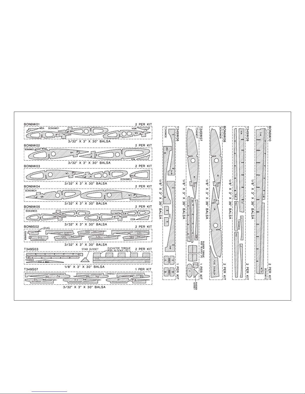
DIE-CUT PATTERNS
IMPORTANT
Do not remove the wing ribs or other wing parts from the die-cut sheets until instructed to do so.
Page 7
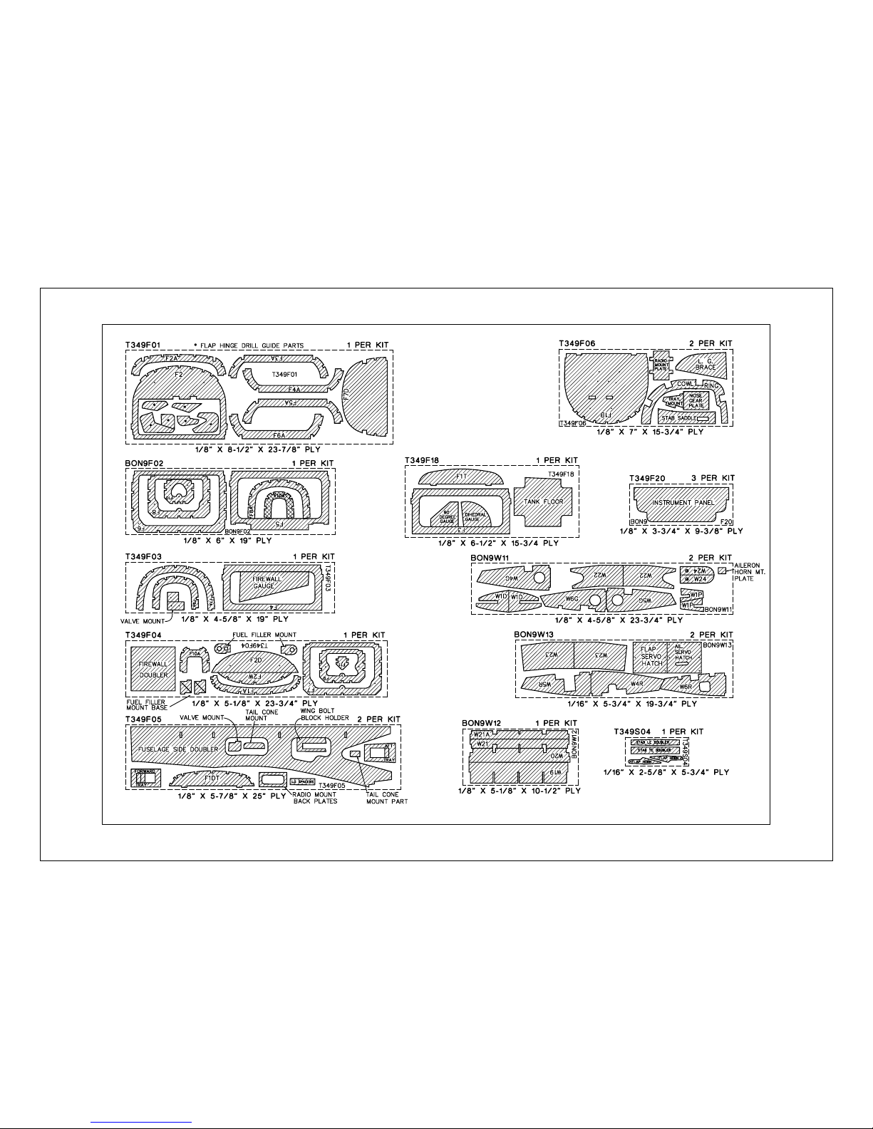
- 7 -
DIE-CUT PATTERNS
Page 8
OTHER ITEMS REQUIRED
Accessories
These are additional items you will need to complete
your T-34B Mentor that are not included with your kit.
Order numbers are in parentheses (GPMQ4130).
Our exclusive brand is listed where possible: TOP is
the Top Flite brand, GPM is the Great Planes brand,
and HCA is the Hobbico®brand.
❏ 4- to 6-channel radio with 6 to 9 servos
❏ (2) 12” extension for ailerons
❏ (2) 6” extension for elevator and rudder servo
❏ (1) “Y” Harness for ailerons
❏ 3-1/2” Main Wheels (ROBQ1516)
❏ 2-3/4” Nose Wheel (ROBQ1513)
❏ 14 oz. Fuel Tank (GPMQ4106)
❏ 2-3/4” Aluminum Spinner (GPMQ4555)
❏ 36” Medium Silicone Fuel Tubing (GPMQ4131)
❏ 1/4” R/C Foam Rubber Padding (HCAQ1000)
❏ 1/5 Scale Pilot Figures. If using Williams Bro.
use (WBRQ2625) - 1/4 scale fits best.
❏ Fuel Filler Valve (GPMQ4160)
❏ Exhaust Deflector (HCAP2175)
❏ 3-4 rolls Top Flite Super MonoKote covering,
see Finishing on page 58
❏ Paint, see Finishing on page 59
❏ Propellers, see the engine instructions
For an In Cowl Muffler setup, the following items
will be required:
O.S.®.61FX & FX Top Flite Header (TOPQ7920)
SuperTigre .75G Top Flite Header (TOPQ7926)
.61-.75 In Cowl Muffler (TOPQ7917)
Note: This muffler is NOT recommended
for .90 or larger size engines.
Building supplies
Here’s a checklist of supplies you should have on
hand while you’re building. We recommend Great
Planes Pro™CA and Epoxy.
Glue/Filler
❏ 4 oz. Thin CA (GPMR6003)
❏ 4 oz. Medium CA+ (GPMR6009)
❏ 2 oz. Thick CA- (GPMR6015)
❏ CA Accelerator (GPMR6035)
❏ CA Debonder (GMPR6039)
❏ CA Applicator Tips (HCAR3780)
❏ 30-Minute Epoxy (GPMR6047)
❏ 6-Minute Epoxy (GPMR6045)
❏ Pro Wood Glue (GPMR6161)
❏ J & Z Products Z RC/56 canopy glue (JOZR5007)
❏ Microballoons (TOPR1090)
❏ Milled Fiberglass (GPMR6165)
❏ Lightweight Hobby Filler (HCAR3401)
❏ Auto Body Filler (Bondo®or similar)
❏ 3M #75 Spray Adhesive (MMMR1900)
❏ Denatured or Isopropyl Alcohol
Tools
❏ #11 Blades (HCAR0311, 100 qty.)
❏ Single Edge Razor Blades (HCAR0312, 100 qty.)
❏ Razor Plane (MASR1510)
❏ X-Acto®Building Square (XACR7726)
❏ X-Acto Building Triangle (XACR7725)
❏ T-Pins (HCAR5100 - Small, HCAR5150 -
Medium, HCAR5200 - Large)
❏ 1/4-20 Tap and Drill Set (GPMR8105)
❏ 8-32 Tap and Drill Set (GPMR8103)
❏ Hobbico Curved Tip Canopy Scissors (HCAR0667)
❏ Long Handle 9/64” Ball Driver (GPMR8004)
❏ Long Handle 3/32” Ball Driver (GPMR8002)
❏ Silver Solder (GPMR8070 w/flux)
❏ Masking Tape (TOPR8018)
❏ Great Planes Plan Protector (GPMR6167) or
waxed paper
❏ Great Planes Dead Center™Tool (GPMR8130)
❏ Easy-Touch™Bar Sanders*
❏ Heat Gun (TOPR2000)
❏ Trim Seal Tool (TOPR2200)
❏ Hot Sock
™
(TOPR2175)
❏ Sealing Iron (TOPR2100)
❏Drill Bits:
1/16”, 17/64”, 3/32”, 9/32”, 1/8”, 5/16”, 5/32”,
9/64” or #29, 3/16”, 11/64” or #10, 1/4”, 13/64”
or #7
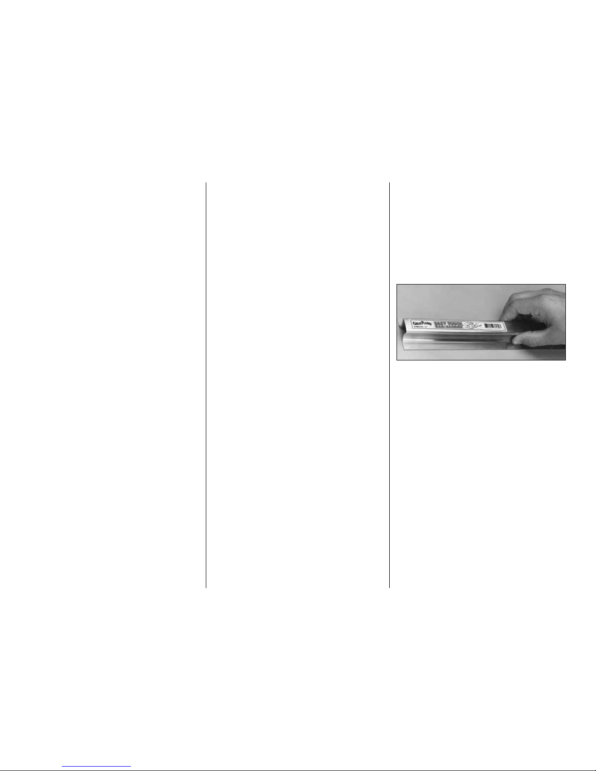
EASY-TOUCH™BAR SANDER
A flat, durable, easy to handle sanding tool is a
necessity for building a well finished model. Great
Planes makes a complete range of patented EasyTouch Bar Sanders and replaceable Easy-Touch
adhesive-backed sandpaper. While building the
T-34B Mentor we used two 5-1/2” Bar Sanders and
two 11” Bar Sanders equipped with 80-grit and 150grit adhesive-backed sandpaper.
Here’s the complete list of Easy-Touch Bar Sanders
and adhesive backed sandpaper:
5-1/2” Bar Sander (GPMR6169)
11” Bar Sander (GPMR6170)
22” Bar Sander (GPMR6172)
12’ roll of Adhesive-backed sandpaper
80-grit (GPMR6180)
150-grit (GPMR6183)
220-grit (GPMR6185)
Assortment pack of 5-1/2” strips (GPMR6189)
We also use 3M 320-grit or 400-grit wet-or-dry
sandpaper for finish sanding.
- 8 -
Page 9
IMPORTANT BUILDING NOTES
There are two types of screws used in this kit:
Sheet metal screws are designated by a number
and a length.
For example #6 x 3/4" long [19.1mm]
Machine screws are designated by a number,
threads per inch, and a length.
For example 4-40 x 3/4" long [19.1mm]
•
When you see the term
test fit
in the instructions,
it means that you should first position the part on
the assembly without using any glue, then
slightly modify or
custom fit
the part as necessary
for the best fit.
•
Whenever the term
glue
is written you should rely
upon your experience to decide what type of glue
to use. When a specific type of adhesive works
best for that step, the instructions will tell you what
glue is recommended.
•
Whenever just
epoxy
is specified you may use
either
30-minute epoxy or6-minute epoxy. When
30-minute epoxy is specified, it is highly
recommended that you use only 30-minute (or
45-minute) epoxy because you will need the
working time and/or the additional strength.
•
Occasionally we refer to the
top
or
bottom
of the
model or upor
down
. To avoid confusion, the
top
or
bottom
of the model is as it would be when the
airplane is right side up and will be referred to as
the top even if the model is upside-down during
that step,
i.e.
the top main spar is always the top
main spar even if the wing is upside-down when
you are working on it. Similarly,
move the former
up
means move the former toward the top of the
fuselage even if the fuselage is upside-down when
you are working on it.
•
Incidence and Thrust Angles: The incidence
angles and down thrust angles shown on the
fuselage side view are in reference to the stepped
main fuselage stringer (the 1/4” x 3/8” x 36”
stepped stringer), which is set at 0°. The right
thrust shown on the bottom view is in reference to
the centerline of the fuselage. Remember, this is
the bottom view so right thrust is viewed as an
offset to the left from the bottom.
•
When you get to each step, read that step
completely through to the end before you begin.
Frequently there is important information or a note
at the end of the step that you need to know before
you start.
•
Photos and sketches are placed before the
step they refer to. Frequently you can study photos in
following steps to get another view of the same parts.
COMMON ABBREVIATIONS
deg = Degrees Ply = Plywood
Elev = Elevator Stab = Stabilizer
Fuse = Fuselage LG = Landing Gear
Lt = Left Rt = Right
" = Inches LE = Leading Edge (front)
TE = Trailing Edge (rear)
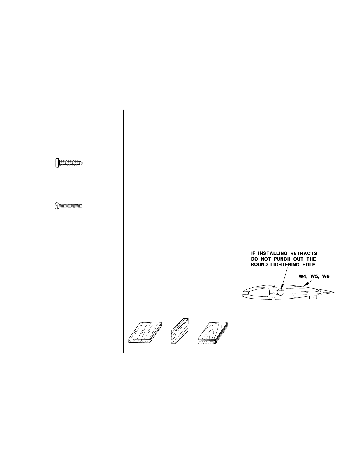
TYPES OF WOOD
BALSA BASSWOOD PLYWOOD
GET READY TO BUILD
1. Unroll the plan sheets. Roll them inside out so
they lie flat.
2. Remove all the parts from the box. Use a ballpoint
pen (not a felt tip pen) to lightly write the name or
size on each piece so you can identify it later. Use
the
die-cut patterns
on pages 6 and 7 to identify and
mark the die-cut parts before you remove them from
their die sheets. Many of the parts already have
numbers stamped on them, but in some cases the
number is located alongside the parts or only on the
die drawings in the manual. Do not remove the die-cut
parts until instructed to do so. If a part is difficult to
remove, don’t force it out but cut around it with a hobby
knife and a #11 blade. After you remove the parts from
their die sheets, lightly sand the edges to remove
slivers or die-cutting irregularities. Save some of the
larger leftover pieces of wood.
Note: If you are going to install retracts, don’t punch out
the round
lightening hole
in the die-cut 3/32” [2.4mm]
balsa wing ribs W4, W5 and W6. Instead, apply thin CA
around the lightening hole to glue it in place.
3. Separate the parts into groups such as stab, fin,
wing, and fuse. Store smaller parts in zipper-top
food storage bags.
- 9 -
Page 10

BUILD THE TAIL SURFACES
MAKE THE SKINS FOR THE
TAIL SURFACES
❏ 1. See the Hot Tip that follows and use six 1/16” x
3” x 30” [1.6 x 76 x 762mm] balsa sheets to make two
1/16” x 9” x 30” [1.6 x 229 x 762mm] stab skin
planks. Make a third plank for the fin/rudder skin
from three more 1/16” x 3” x 30” [1.6 x 76 x 762mm]
balsa sheets.
❏ 2. After the glue is dry, peel off the masking tape
and decide which side of the planks will be the
outside. Use a bar sander or a large, flat sanding
block and 150-grit sandpaper to sand the outside of
the planks so they are flat, even and smooth. The
idea is to do the sanding
before
you glue the skins
to the structure.
❏ 3. Cut the three 9” x 30” [229 x 762mm] sheets in
half, making six 9” x 15” [229 x 381mm] planks.
F. Place weights along the glue joint and let the
glue dry.
G. Use the same procedure to make the wing
skins when you build the wing.
E. Press the joining edges of the sheets down
with your fingers so they are flat and even.
D. Use a credit card or a piece of thin plywood to
simultaneously press the sheets flat as you
squeegee the excess glue from the seam.Wipe the
glue off your squeegee with a paper towel or a stick
of wood. Immediately proceed to the next step.
C. Place waxed paper on your workbench. Flip
the sheets over and apply a bead of aliphatic
resin (
wood workers glue
such as Great Planes
Pro™) between the seams. Immediately proceed
to the next step.
B. Tightly tape the sheets together with masking
tape placed about every 4” along the seams.The
sheets will not lay flat because they are tightly
taped together
A. Use a straightedge and a sharp #11 blade to
true the joining edges of the sheets. When you
trim them, do not cut all the way through the first
time but make several passes so you slice the
wood instead of splitting it.
HOW TO MAKE THE SKINS
- 10 -
Page 11
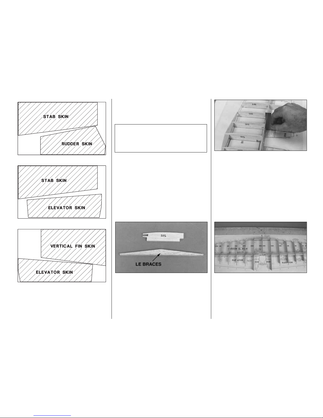
❏ 4. Cut the stab, elevator, vertical fin and rudder
skin templates from the plan. Use a straightedge
and ballpoint pen to mark their outline onto the 9” x
15” [229 x 381mm] planks (do not use a felt-tip pen).
The templates are slightly oversize to allow slight
variances in construction. Note the grain direction.
Follow this sequence:
(2) planks – stab and rudder.
(2) planks – stab and elevator.
(2) planks – vertical fin and elevator.
BUILD THE STABILIZER
AND ELEVATORS
Build the right and left stab halves simultaneously.
❏ 1. Position the plan so the stab is over your flat
building board (or cut the stab from the plan), tape it
down and cover it with waxed paper or Plan Protector.
❏ 2. Glue both die-cut 1/8” [3.2mm] balsa LE braces
together and both die-cut 3/32” [2.4mm] balsa S1S
ribs together.
❏ 3.Test fit the die-cut 3/32” [2.4mm] balsa stab ribs
S2S through S7S in the notches of both die-cut 1/8”
[3.2mm] balsa stab TE spars (S9). Make a left and
right assembly. Place both assemblies over the plan
and add the LE brace. See the photo at step 4.
❏ 4. Use a small square to align the stab TE spar at
rib S2S over the plan. Pin rib S2S over its location on
the plan with a T-pin about 1/4” in front of the TE spar.
Note: The above photo shows S1S in place, but it is
not installed until step 11.
❏ 5. Use the same method to align the TE spar and
pin the rest of the ribs on both sides of the stab to
your building board over the plan.
❏ 6. Pin the fronts of the ribs to your building board
over the plan.
❏ 7. Add both die-cut 1/8” [3.2mm] balsa elevator
LE spars (S8) to the assembly.
❏ 8. Make sure all the jig tabs of all the ribs are
contacting your building board. Glue the stab TE
spar and elevator LE spar to the ribs with medium
CA. Don’t use large amounts of CA or build up fillets
of glue. Later we will instruct you to reinforce glue
joints that don’t look strong.
Beech Fact: In 1946 Walter H. Beech announced
his all new, revolutionary, single engine entry in the
postwar market. He named it the Bonanza,
descriptive of an extra value offered in the way of
economy, performance and pleasure to the owner.
-11-
Page 12
Use this photo for the next three steps.
❏ 9. Glue the 1/4” x 5/8” x 4-3/8” [6.4 x 15.9 x
111mm] balsa TE center brace to the front of the
stab TE spars of both stab halves.
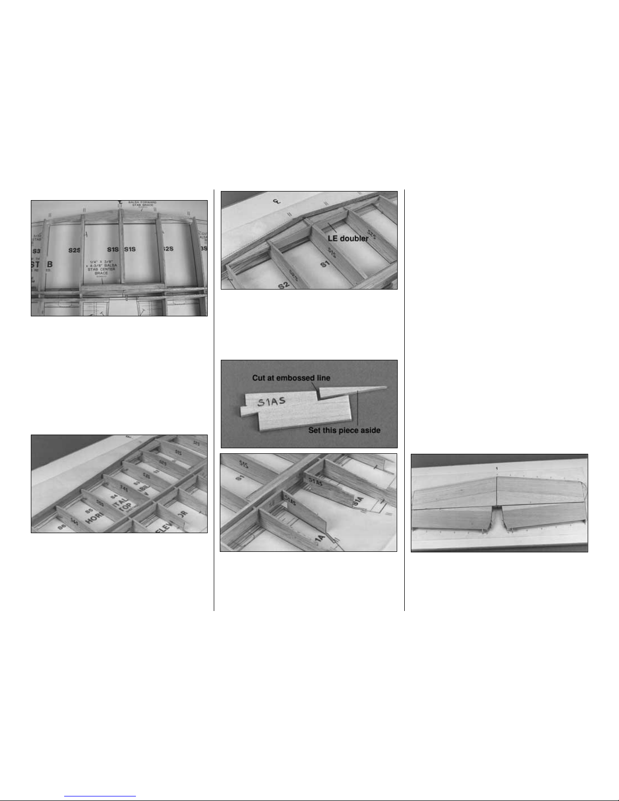
❏ 10. Glue the die-cut 1/16” [1.6mm] plywood TE
doubler to the front of the TE brace (it’s the one with
straight edges).
❏ 11. Add the die-cut 3/32” [2.4mm] balsa center rib
S1S and glue it into position.
❏ 12. Sand the fronts of the ribs to match the aft
sweep of the leading edge. Cut two shaped 5/16” x
15” [7.9 x 381mm] balsa stab/fin leading edges to
a length of 13-3/4” [349mm] and bevel the joining
ends to match the plan. Glue them to the ribs and the
LE brace so the top edge is even with the top of the
ribs. The bottom will extend below the ribs but will be
sanded flush later.
❏ 13. Cut a 1/16” [1.6mm] notch in center rib S1S
behind the LE brace. Test fit the die-cut 1/16”
[1.6mm] plywood LE doubler in the notch. Deepen
the notch as necessary so the top of the doubler is
even with the top of rib S1S. Glue the doubler to the
LE brace and glue rib S1S to the doubler.
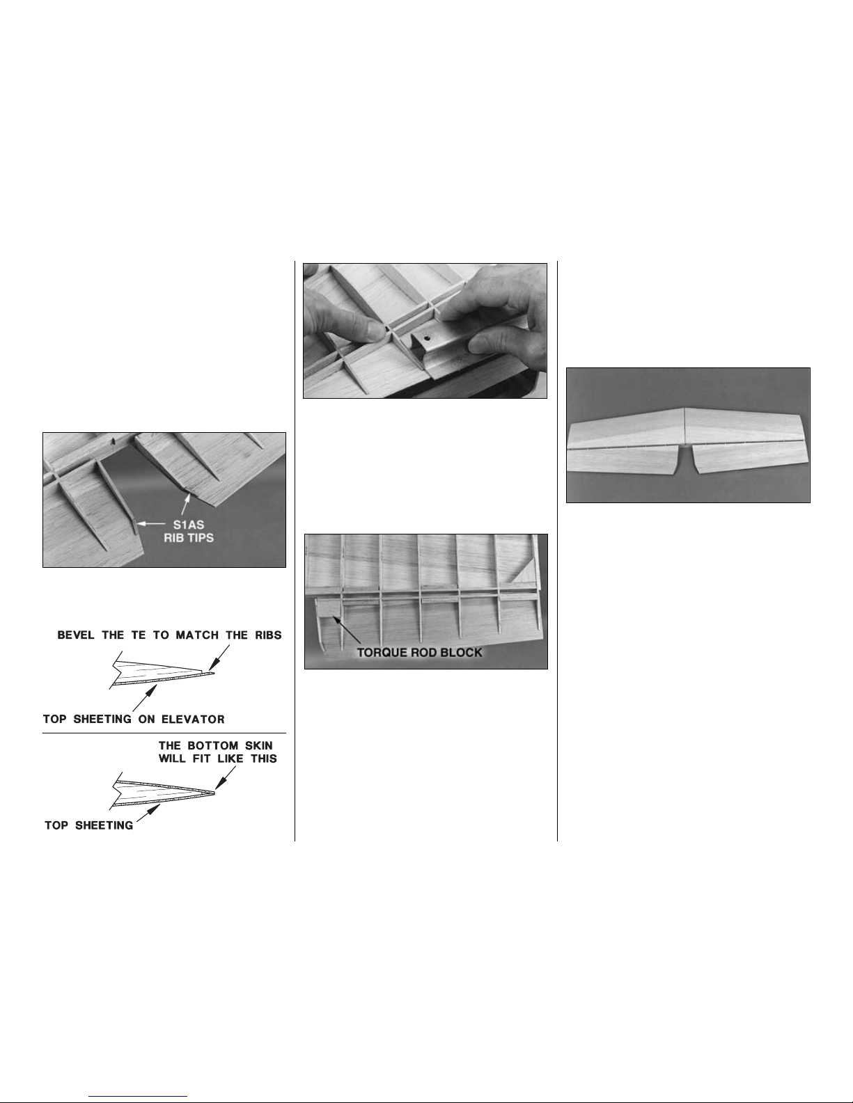
❏ 14. Cut the end off both die-cut 3/32” [2.4mm]
balsa S1AS ribs at the embossed line and set those
little pieces aside. They will be used later to glue the
aft end of S1AS into position. Fit the S1AS’s to the
elevator LE spars, pin them to the plan, and then
glue them to the elevator LE spars.
❏ 15. Sand the top of the leading edges, stab and
elevator spars, and the TE brace so they match the
contour of the ribs. Do not change the shape of the
airfoil by sanding too much.
❏ 16. THIS STEP IS VERY IMPORTANT! Arrange
the T-pins so every other rib is held down with one
pin near the front and one pin near the rear and
make sure all the pins go into the jig tabs at the
same angle. This will allow you to remove the stab
from your building board by lifting it up and to one
side after the top sheeting is glued in place (because
the T-pins are concealed).
❏ 17. Use your favorite method to glue the stab skin to
the stab.We recommend using aliphatic resin to glue the
skin to the ribs and TE spar, and medium CA for only the
leading edge. Apply glue to the stab structure. Working
quickly, position the stab skin and hold the leading edge
down until the CA hardens. When the CA is hardened,
wet the front of the skin with a 50/50 mix of alcohol and
water and press it to the rest of the frame, holding it
down with weights until the glue dries.
Note: If you choose to use CA for the entire job, be
aware that residual accelerator you may have used
earlier can make the CA you use for this step cure
quickly. You’ll have to work rapidly.
❏ 18. Glue the elevator skin to the elevator. You can
use CA for this step since the skin is small and easy
to position. Make sure the trailing edge contacts the
stoppers on the top of the jig tabs on ribs S7S and
S2S. Note: You may have to trim the LE of the skin
to fit it into position.
-12-
Page 13
❏ 19. After the glue has thoroughly dried, remove all
the T-pins you can reach. Carefully lift the stab (with
the elevators) from your building board. Trim the jig
tabs from the ribs and take out the rest of the T-pins.
❏ 20. Use a razor plane or a #11 blade to trim the
bottom of the LE so it is the same size as the front
of the ribs and matches the airfoil shape.
❏ 21. Sand the bottoms of the ribs, leading edges,
stab spars, elevator spars and the TE brace so they
smoothly blend.
❏ 22. Glue the little tips you cut off the end of the
S1AS ribs to the sheeting and S1AS.
❏ 23. Use a bar sander and 150-grit sandpaper to
bevel the trailing edge of the top elevator skin so it will
accommodate the bottom skin. While you sand, apply
pressure only to the sheeting and use the ribs to set
your sander at the correct angle. Do not bevel the
trailing edge to a
sharp edge
but leave about 1/32”
[0.8mm]
squared off
. Hint: Support the TE with the
edge of your workbench or a platform while you sand.
❏ 24. Glue four die-cut 1/8” [3.2mm] balsa elevator
torque rod blocks between both sets of ribs S1AS
and S2S.
❏ 25. Cut twelve 1-7/8” [47.6mm] long hinge blocks
from the 1/4” x 3/8” x 36” [6.4 x 9.5 x 914mm] balsa
stick. Glue them evenly spaced vertically to the stab
TE spar and the elevator LE spar where shown on
the plan. Glue the die-cut 1/8” [3.2mm] balsa stab
gusset to the hinge block and rib S7S as shown on
the plan. Position the gusset so it is even with the
bottom of the hinge block so you do not break it
when you cut the hinge slot.
❏ 26. Trim the elevator torque rod blocks and any
protruding hinge blocks so they are even with the
bottoms of the ribs.
❏ 27. Reinforce any glue joints that do not look strong.
Use this photo for the next two steps.
❏ 28. Glue the elevator skins to the bottom of the
elevators so the trailing edges align.
Optional: Use the die-cut 1/8” [3.2mm] balsa stab
cradles S2T and S7T to hold the stab flat on your
workbench while you glue the bottom skins on. Use
the stab cradles the same as the wing cradles shown
in steps 1-5 on page 28.
❏ 29. Glue the stab skins to the bottom of the stab.
If you have not used any accelerator on the stab you
may glue the skins on with thick or medium CA.
Otherwise, use aliphatic resin. Work over a flat work
surface and be careful not to add any twist into the
stab as you press the skins to the stab frame.
❏ 30. After the glue dries, use a bar sander with 150-
grit sandpaper to sand the sheeting even with the
ends of the stab and elevators.
❏ 31. Cut the ribs and separate the elevators from
the stab. Sand the excess sheeting and rib stubs
from the TE of the stab and the LE of the elevator.
Sand the elevator sheeting even with rib S1AS.
-13-
Page 14
❏ 32. Glue a die-cut 1/8” [3.2mm] balsa stab TE
(S10) to the TE of both stab halves. Glue a die-cut
1/8” [3.2mm] balsa elevator LE (also S10) to the LE
of both elevators.
❏ 33. Sand the stab TE’s and the elevator LE’s so
they are even with the ends of the stab and
elevators. Sand the stab TE and elevator LE’s so
they blend with the tips and skins.
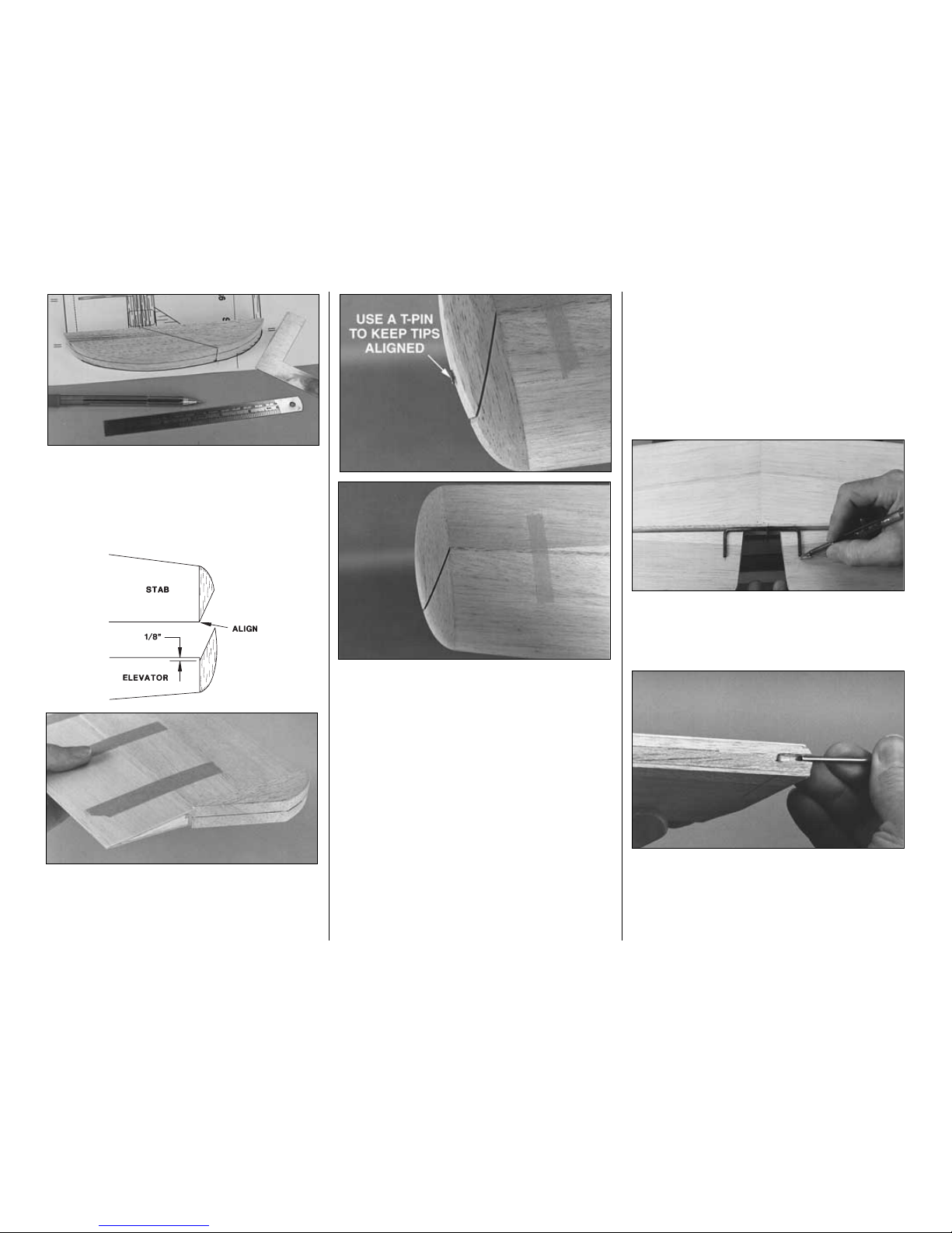
❏ 34. Use two T-pins, placed in the center of the
leading edge of one of the elevators near the ends,
to align a straightedge and draw a centerline with a
ballpoint pen.
❏ 35. Mark the other elevator and the TE of the stab
the same way.
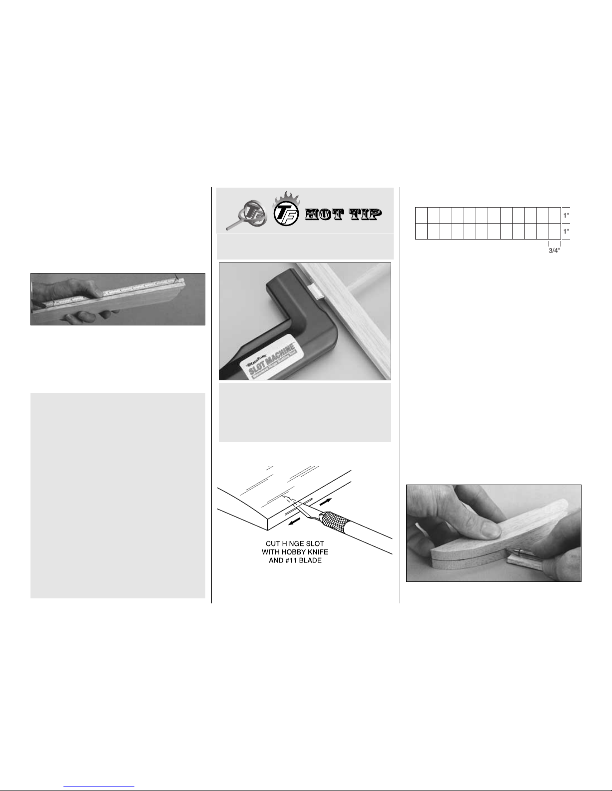
❏ 36. Cut the hinge slots on the centerlines of the
elevators and the stab where shown on the plan.
❏ 37. Cut six hinges from the 2” x 9” [51 x 229mm]
CA hinge strip as shown in the sketch. Snip the
corners off the hinges so they go into the slots
easier. Temporarily join both elevators to the stab
with the hinges. If necessary, adjust the hinge slots
so the elevators and stab align.
❏ 38. Locate the 3/4” x 1-3/8” x 6-1/2” [19 x 35 x
165mm] shaped balsa stab tip blocks.
❏❏39. Securely tape the elevator to the stab with
masking tape on both sides. Sand the ends of the
stab and elevators so they are even.
❏❏40. Draw a centerline all the way around a 3/4”
[19mm] shaped balsa stab tip block.
We HIGHLY recommend that you use the Great
Plans Slot Machine™for cutting your hinge slots.
This motorized hinge slotting tool makes clean
slots of the exact size needed for CA hinges.
Once you use this tool, you will never cut your
hinge slots any other way.
HOW TO MAKE THE HINGE SLOTS
IMPORTANT NOTES ABOUT CA HINGES
This kit is supplied with a CA hinge material
consisting of a 3-layer lamination of Mylar and
polyester. It is specially made for hinging model
airplane control surfaces. When properly installed,
this type of CA hinge provides the best
combination of strength, durability and easy
installation. We trust all of our Gold Edition
warbirds to these hinges, but it is essential to
install them correctly. Carefully follow the hinging
instructions in this manual for the best result.
The most common mistake made by modelers
when installing CA hinges is making the hinge
slots too tight, restricting the flow of CA to the
back of the hinges; or not using enough glue to
fully secure the hinge over its entire surface area.
This results in hinges that are only
tack glued
into
the hinge slots. The techniques for cutting the
hinge slots and gluing in the CA hinges (near the
end of the manual) have been developed to
ensure thorough and secure attachment.
-14-
Page 15
❏❏41. Place the stab tip block over its location on
the plan. Mark where the elevator tip meets the stab
tip on both sides of the block.
❏❏42. Cut the stab tip from the elevator tip. True
the edges you just cut with a bar sander.
❏❏43. Glue the stab tip to the stab. The sharp
point
of the stab tip should align with the TE of the
stab. Glue the elevator tip to the elevator so it is 1/8”
[3.2mm] aft of the LE and aligns with the stab tip (as
shown in the sketch).
❏❏44. Use a razor plane or a hobby carving knife,
followed by sanding to carefully shape the elevator
and stab tip. Inspect your progress frequently. Use
the centerlines as a guide and the plan as a
reference so you know what the curve of the tip
should look like.
Hint: Stick a T-pin through the elevator tip into the
stab.This will hold the elevator tip while you shape it.
Note: When you shape the left stab tip, in addition to
the plan, use the finished tip on the right stab as a
guide to shape the left stab tip. This way you can
make sure both of the stab tips are identical.
❏❏45. Shape the stab LE as shown on the plan.
❏❏46. Separate the elevator from the stab.
❏❏47. Shape the leading edge of the elevator to a
“V” as shown on the plan. Use the centerline on the
leading edge as a guide. Make sure that the angle of
the “V” will allow the throws indicated in the back of
the manual.
❏ 48. Go back to step 39 and do the other stab tip.
❏ 49. Using the plan, accurately mark the location of
the 1/8” [3.2mm] elevator joiner wire and horn
(from now on referred to as just the
elevator joiner
)
on the elevators.
❏ 50. Drill a 9/64” [3.6mm] hole 1-1/4” deep and cut
a groove in the center of both LE’s for the joiner.Test
fit the elevator joiner in the elevators.
Hint: Use a 1/8” [3.2mm] brass tube sharpened at
one end to cut the grooves.
-15-
Page 16
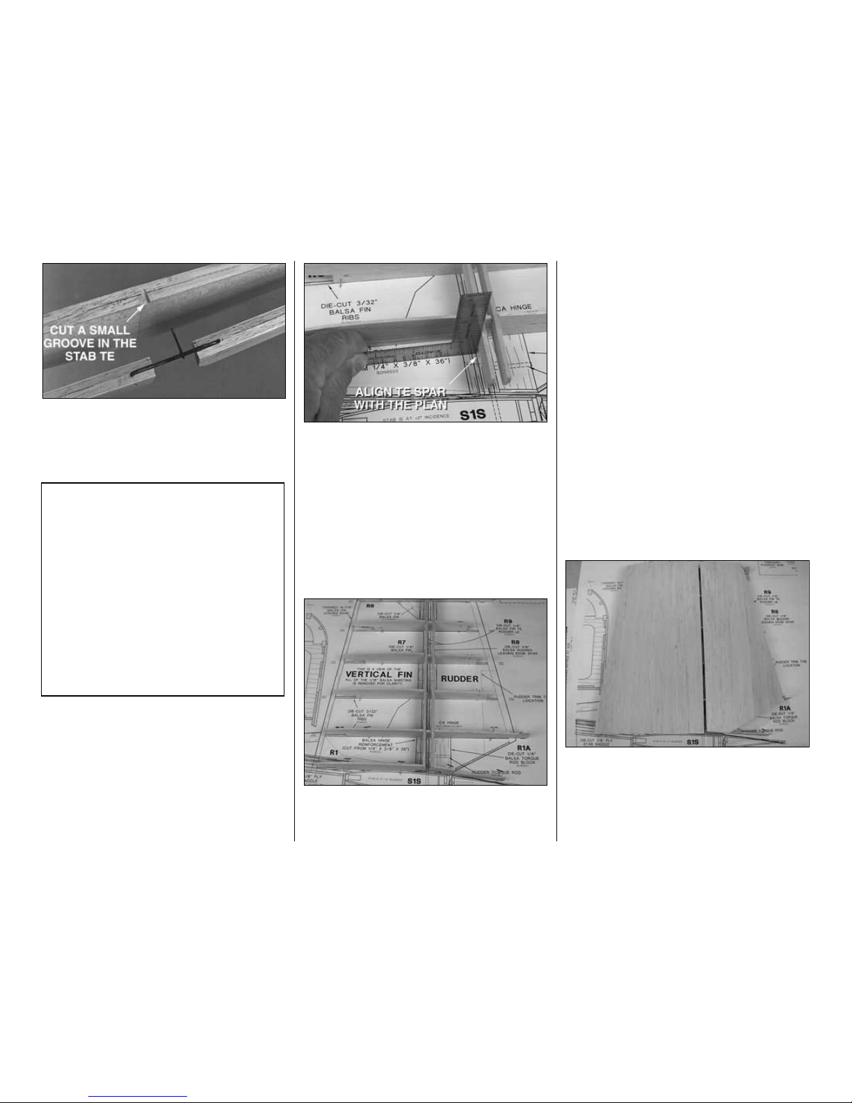
❏ 51. Cut a small groove in the TE of the stab so the
horn on the elevator joiner will not bind against the
stab when the elevator deflects downward. Test fit
the elevators to the stab, with the elevator joiner in
place, and make adjustments if necessary.
BUILD THE FIN AND RUDDER
❏ 1. Place the fin plan over your building board and
cover it with Plan Protector or waxed paper.
❏ 2. Test fit the die-cut 3/32” [2.4mm] balsa fin ribs
R2 through R6 in the notches of the die-cut 1/8”
[3.2mm] balsa fin TE spar (R7) and rudder LE spar
(R8). Place the assembly over the plan.
❏ 3. Use a small square to position the fin TE spar
over the plan near rib R2. Align rib R2 over the plan
and pin it to your building board. Use one T-pin near
the front of the jig tab and one T-pin near the rear of
the jig tab.
❏ 4. Use the same method to align the fin TE spar
over the plan at each rib. Pin the rib to your building
board. Glue the ribs to the spars with medium CA.
Use small drops of CA and do not build up fillets.
Later, we will remind you to reinforce the glue joints.
Refer to this photo for the next three steps
❏ 5. Pin rib R1 in place and glue it to the spar. Cut
the end off rib R1A at the embossed line and set the
cut-off piece aside. Pin the remaining part of R1A in
place and glue it to the rudder LE spar.
❏ 6. Sand the fronts of the ribs to match the aft
sweep of the leading edge. Cut a shaped 5/16” x 15”
[8 x 381mm] balsa stab/fin leading edge to a length
of 11” [280mm]. Glue it to the front of the ribs so the
top edge of the LE is even with the top of the ribs.
The bottom of the LE will extend below the bottom of
the ribs but will be sanded flush later.
❏ 7. Sand the upward facing edges of the leading
edge and the sub spars so they match the contour of
the ribs. Do not change the shape of the airfoil by
sanding too much.
❏ 8.Arrange the T-pins so they all go into the jig tabs
at the same angle. This will allow you to remove the
fin and rudder from your building board by lifting it up
and to one side after the top sheeting is glued in
place (because the T-pins are concealed).
❏ 9. Glue the fin and rudder skin to the structure. The
bottom of the fin skin should extend below rib R1 by
approximately 1/4” [6.4mm] so you can trim it later.
Make sure the trailing edge of the rudder meets the
stoppers on the top of the jig tabs on ribs R2 and R6.
Note: The rudder skin was cut wider than needed, to
allow enough material to trim it to size now.
T-34 Fact: The T-34 began as a private venture by
Walter Beech shortly after the end of WWII. The
Beechcraft Model 35 Bonanza had been
developed and Mr Beech felt there was a market
for a military trainer based on the Bonanza. After
the war, there were over 50,000 war-surplus
trainers still in the inventory and there was a lack
of funding for a new trainer, so Beech built several
proof of concept aircraft as a private venture.They
used the same basic wing, landing gear and
some fuselage parts from the Bonanza and one
even had the classic V-tail. These aircraft were
developed under the company designation Model
45. The first prototypes use a 205 hp Continental
engine while later prototypes used a more
powerful 225 hp engine.
-16-
Page 17
❏ 10. After the glue has thoroughly dried, remove all
the T-pins you can reach. Carefully lift the fin (with
the rudder) from your building board.Trim the jig tabs
from the ribs and take out the rest of the T-pins.
❏ 11. Use a razor plane or a #11 blade to trim the
right side of the LE so it is the same size as the front
of the ribs and matches the airfoil shape.
❏ 12. Sand the ribs, leading edges, fin spar, rudder spar
and trailing edges so that they blend.
❏ 13. Glue the end of R1A, that was cut off earlier,
to the sheeting and to R1A.
❏ 14. Bevel the trailing edge of the left rudder skin
the same way you did the stab.
❏ 15. Glue the four die-cut 1/8” [3.2mm] balsa
rudder torque rod blocks between ribs R1A and
R2 in the rudder.
❏ 16. Cut five 1-7/8” [47.6mm] long hinge blocks
from the 1/4” x 3/8” x 36” [6.4 x 9.5 x 914mm] balsa
stick. Test fit, then glue the hinge blocks, evenly
spaced vertically, to the fin TE spar and the rudder
LE spar where shown on the plan.
❏ 17.Glue the die-cut 1/8” [3.2mm] balsa fin gusset
to the hinge block and rib R6. The gusset should be
raised so it is even with the left side of the fin TE and
rib R6 (so it does not interfere with the hinge slot).
❏ 18. Trim the rudder torque rod blocks and any
hinge blocks so they are even with the ribs.
❏ 19. Reinforce all glue joints that don’t look strong.
❏ 20. Glue the other rudder and fin skin to the right
side of the rudder and fin. Optional: Use the die-cut
1/8” [3.2mm] balsa fin/stab cradles R1C and R6C to
hold the fin and rudder flat on your workbench while
you glue the right skins on.
❏ 21. Sand the tip of the fin and rudder sheeting
flush with rib R6.
❏ 22. Cut the ribs and separate the rudder from the
fin. Sand the excess sheeting and rib stubs from the
TE of the fin and the LE of the rudder. Sand the
bottom of the rudder even with rib R1A.
❏ 23. Glue a die-cut 1/8” [3.2mm] balsa fin trailing
edge (R9) to the fin TE spar and a die-cut 1/8”
[3.2mm] balsa rudder leading edge (R9) to the
rudder LE spar. Sand the fin TE and rudder LE so
they blend with the tips and skins.
❏ 24. Use the
straightedge and pin
technique to
draw a centerline on the LE of the rudder and the TE
of the fin.
❏ 25.Cut the hinge slots on the centerline of the fin
and rudder where shown on the plan.
❏ 26. Cut three more hinges from the hinge strip and
temporarily join the rudder to the fin. If necessary,
adjust the hinge slots so the fin and rudder align.
❏ 27. Securely tape the rudder to the fin with
masking tape on both sides. Sand the ends of the fin
and rudder so they are even.
❏ 28. Draw a centerline on the top and bottom of the
3/4” x 1-7/16” x 7-3/8” [19 x 36.5 x 187mm] balsa fin
tip block. Cut the block into two pieces as shown on
the plan. Sand the edges you just cut so they are
smooth and match the angle on the plan.
Use this photo for the next two steps.
❏ 29. Use thick or medium CA to glue the rudder and
fin tip blocks to the rudder and fin in the same manner
that you glued the tip blocks to the elevator and stab.
Use the centerline on the tip blocks as a guide to make
sure it is centered on the rudder and fin.
❏ 30. Use a razor plane or a hobby carving knife
followed by sanding to carefully shape the fin and
rudder tip blocks. Inspect your progress frequently
and use the centerlines as a guide.
Hint: Stick a T-pin through the top of the rudder tip
into the fin. This will hold the rudder tip while you
shape it.
❏ 31. Shape the LE of the fin as you did with the stab.
❏ 32. Separate the rudder from the fin.
❏ 33. Shape the leading edge of the rudder to a “V”
as you did with the elevators. Use the centerline on
the leading edge as a guide. Make sure the angle of
the “V” will allow the throws indicated in the back of
this manual.
-17-
Page 18
What a nice piece of workmanship! Put the stab and
fin in a safe place, clean off your workbench, vacuum
the floor, then read the following T34 Fact.
BUILD THE WING
MAKE THE WING SKINS
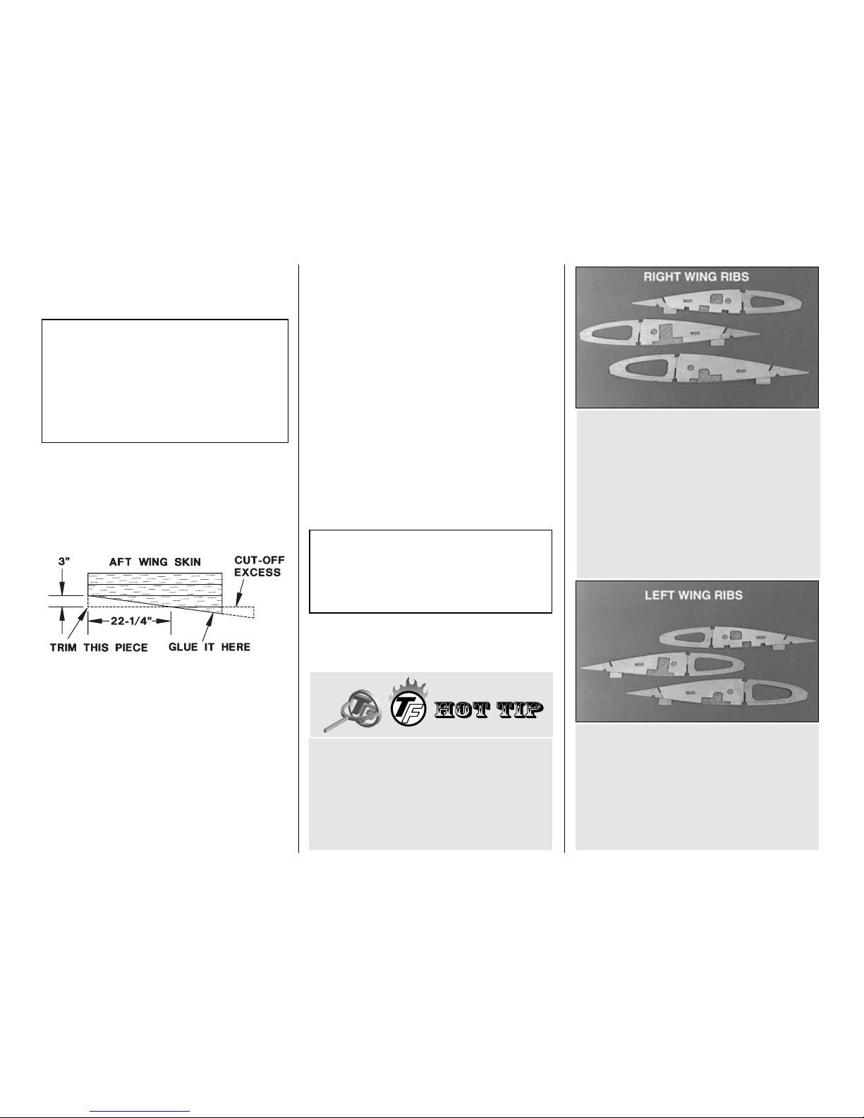
❏ 1. Glue three 3/32” x 3” x 36” [2.4 x 76 x 914mm]
balsa sheets together to make an aft wing skin.Trim
a
wedge
from the aft wing skin. Glue it back onto the
skin as shown in the sketch.
❏ 2. Glue two 3/32” x 3” x 30” [2.4 x 76 x 762mm]
(not 36” [914mm]) balsa sheets together to make the
forward outer wing skin.
Note: You will need a total of
four
aft wing skins and
five
forward outer wing skins (one of the forward wing
skins will be cut into four pieces to make the forward
inner skins).You can make all the wing skins now in an
assembly line fashion or make them as needed.
❏ 3. After the glue dries, remove the masking tape
and mark the best side of each skin as the top. Sand
the bottoms of both wing skins so they are flat (or
almost flat). Sand the tops of the skins so they are
flat and smooth.
PREPARATIONS
❏ 1. Unroll the wing plan. Roll it inside out so it will
lie flat. Cut the right wing panel with the center
section from the wing plan. Position it on your flat
building board and cover the plan with Plan Protector
or waxed paper.
Perform steps R2 through R6 if you are installing
retractable landing gear.
R3. Prepare a set of left wing ribs the same way
but use the photo above to make sure you glue
the doublers to the correct side of the ribs.
R4. Remove the shaded area of balsa shown in the
previous two photos after the epoxy is fully cured.
R2. Prepare a set of right wing ribs by using
30-minute epoxy to glue the die-cut 1/16” [1.6mm]
plywood retract landing gear rib doublers
W4R, W5R and W6R to the die-cut 3/32” [2.4mm]
balsa ribs W4, W5 and W6
exactly
as shown in
the photo. Make sure the doublers are on the side
of the ribs as shown in the photo and on the right
wing plan.
Have you purchased your retracts yet? If you
have (or as soon as you do), take the neoprene
air lines out of the package and hang them from
a hook somewhere in your shop, letting them
dangle under their own weight. This will get all the
kinks out and make them easier to work with
when it’s time to install them.
During construction of the wing and fuselage,
some steps refer to fixed gear installation and
other steps refer to retractable gear installation.
Steps for fixed gear start with “F” and steps for
retractable gear start with “R”.
T34 Fact: The Model 45 made its first test flight
on December 2, 1948. After the U.S. Air Force
was shown the prototypes, they ordered three test
aircraft under the designation YT-34. The Model
45 made its’ public debut at the 1949 Cleveland
Air Races and was flown by Bevo Howard and
Betty Skelton. Bevo Howard’s Hawthorn Aviation
later became the Air Force’s first contract flight
school to use the T-34.
-18-
Page 19
Perform steps F7 through F10 only if you are
installing fixed landing gear.
❏ F7. Prepare a set of right wing ribs by using
30-minute epoxy to glue the die-cut 1/8” [3.2mm]
plywood fixed landing gear rib doublers W4G,
W5G and W6G to the die-cut 3/32” [2.4mm] balsa
ribs W4, W5 and W6
exactly
as shown in the photo.
Make sure the doublers are on the side of the ribs as
shown in the photo.
❏ F8. Prepare a set of left wing ribs the same way
but use the photo above to make sure you glue the
doublers to the correct side of the ribs.
❏ F9. Remove the shaded area of balsa shown in
the previous two photos after the epoxy is fully cured.
Note: Details for fixed landing gear are shown on the
left wing plan.
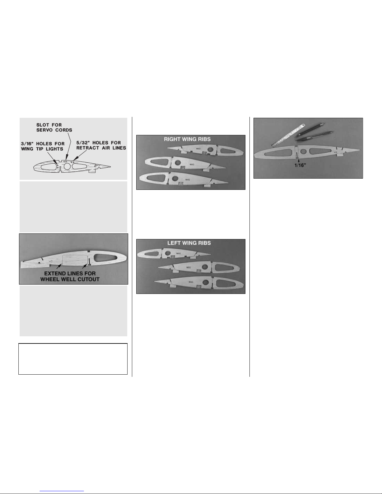
❏ F10. Cut slots at the locations suggested in the
sketch in both sets of ribs W2, W3 and W4 for the servo
leads. Make the slots large enough so the connectors
on the ends of your servo leads will pass through.
(See R5)
❏ 11. Use a straightedge and a ballpoint pen to mark
a vertical line 1/16” [1.6mm] from the front and back
of the spar notches in both W2 ribs. Use a sharp
hobby knife to lightly cut halfway through the balsa
along the lines. You will remove this section of balsa
to accommodate the spar joiners when it is time to
join the wing.
BUILD THE OUTER WING PANELS
For clarity, some of the photos show the wing off the
building board without the plan, but of course you
should build your wing over the plan as we do.
Build the right wing panel first so your progress
matches the photos.
❏❏1. Do not use any glue until step 8. Pin a 1/4”
x 3/8” x 36” [6.4 x 9.5 x 914mm] basswood bottom
spar over its location on the plan so the root end
extends past the dashed line by about 1/8” [3.2mm].
Stick the pins through the spar at an angle so they
will not interfere with the spar web when you position
it in the next step.
T-34 Fact: The T-34 ended up being the last
project done by Walter Beech, who died of a heart
attack late in 1950. Of the six prototype/service
test aircraft, only one remains and is on static
display at March AFB.
R6. Use a ballpoint pen to
extend
the die-cut
wheel well cutout
in both W3 ribs. Cut partway
through the rib along the line so the cutout will be
easier to remove later.
Note: Details for retractable landing gear are
shown on the right wing plan.
R5. Drill 5/32” [4mm] holes and cut slots at the
locations suggested in the sketch in both sets of ribs
W2, W3 and W4 for the retract air lines and servo
leads. Make the slots large enough so the
connectors on the ends of your servo leads will pass
through. Hint: An appropriate size brass tube
sharpened at one end cuts very clean holes.
-19-
Page 20
❏❏2. Test fit ribs W2 through W14 to the die-cut
1/8” [3.2mm] balsa spar web (W15). If necessary,
deepen the notches (in the ribs or in the spar web)
so the ribs fit all the way into the spar web.
Note: Do not be concerned if the ribs do not exactly
align spanwise with the plan. Paper plans can
expand and contract as much as 1/8” [3.2mm] due to
moisture.
❏❏3. Fit the ribs and spar web to the bottom spar
so the ribs align as close as possible with the plan.
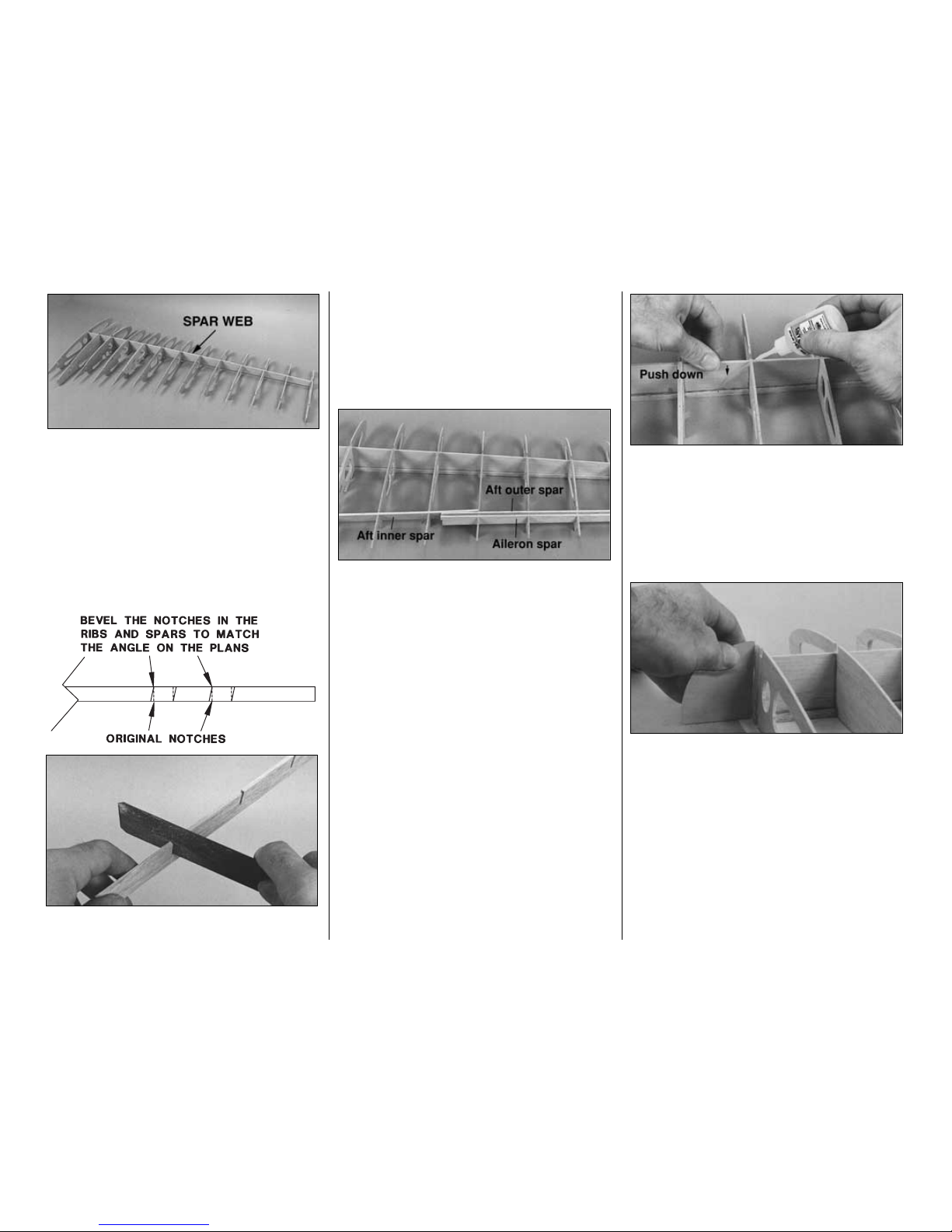
❏❏4. Test fit the die-cut 1/8” [3.2mm] balsa aft
inner spar (W18) into the notches of ribs W2
through W9. If the spar fits too tightly use a single
edge razor blade or a flat Perma-Grit sander to bevel
the notches in the ribs and the spar at the same
angle that they cross. Reinstall the aft inner spar.
❏❏5.Test fit the die-cut 1/8” [3.2mm] balsa aft outer
spar (W16) and the die-cut 1/8” [3.2mm] balsa aileron
spar (W17) into the notches of ribs W9 through W14. If
necessary, bevel the notches in the spars and ribs the
same way you did in the previous step.
❏❏6. Temporarily remove rib W2 from the assembly.
❏❏7. One at a time, accurately align the jig tabs of
all the ribs with the plan and pin them to your building
board. In addition to T-pins, place weights on top of
the ribs and the aft spars to insure that all the jig
tabs are contacting your building board. Inspect
all joints and make sure everything aligns with the
plan. The spar web must fully contact the bottom
spar. A die-cut 1/8” [3.2mm] plywood 90 degree
gauge is supplied in the kit to help you keep the ribs
vertical as you glue them.
❏❏8. Use medium or thin CA to glue all the joints.
Use the CA sparingly at this stage of construction
and do not build up fillets. This will allow you to
realign parts if necessary and keep you from gluing
the jig tabs to the ribs. We will remind you to reinforce
all glue joints later.
❏❏9. Place rib W2 back onto the assembly. Align
W2 with the dashed line depicting where it contacts
the plan. Use the die-cut 1/8” [32.mm] plywood
dihedral gauge to set W2 at the correct angle. Glue
it to the bottom spar and the spar web. Glue W2 to
the aft inner spar using the dihedral gauge to set it at
the correct angle.
❏❏10. Test fit a 1/4” x 3/8” x 36” [6.4 x 9.5 x
914mm] basswood upper spar in the notches of the
ribs so the end of the spar aligns with rib W2. Glue
the spar to the ribs and the spar web with thick or
medium CA. Remember, don’t use too much glue.
-20-
Page 21

❏❏11. Cut a 1/4” x 36” [6.4 x 914mm] shaped
balsa leading edge to a length of 29-1/2” [749mm].
Glue the LE to ribs W4 through W14 so the top aligns
with the tops of the ribs (the same as on the stab).
❏❏12.Bevel the end of the remaining piece of 6-1/2”
[165mm] leading edge so it matches the LE on the wing
when you position it on ribs W4, W3 and W2. Glue it in
position. Glue rib W4A to the side of rib W4. Hint: Glue
the LE to rib W2
last
so you can use the dihedral gauge
to make sure W2 is at the correct angle.
Note: Use a long straightedge along the length of
W2 to insure that it is flat along it’s length (from the
LE to the TE).
SHEET THE TOP OF THE WING PANELS
❏❏1. Use a large sanding block or a bar sander
with 150-grit sandpaper to sand the tops of the top
spar, aft spars, LE and ribs so they all smoothly
blend together. Make sure the tops of the aft spars
match the tapering angle of the ribs but sand the ribs
lightly so you maintain the designed airfoil shape.
❏❏2. Remove the T-pins from the bottom spar and
replace them so they are all sticking in from the front.
This way you will be able to remove them when the
aft top sheet is in position. Remove the T-pins from
the aft jig tabs and replace them in every other jig tab
so they all go into the building board at the same
angle (
you know the drill
). Remove the weights from
the top of the wing (if you used them).
Note: If you observe that the wing panel remains flat
and all the jig tabs are contacting your building board
when you remove the T-pins, you may leave the
T-pins out of the jig tabs. In this case the weights that
will be used to hold the sheeting to the ribs will be
enough to hold the wing flat to your building board.
Use this photo and the sketch for the next few
steps. This photo shows a few weights on top of the
wing, but in actuality we used enough weights to fully
cover the skins. You can use magazines for weights
too. T-pins in the front ensure that the skins are
securely bonded to the top spar.
❏❏3. Trim the aft wing skin so it fits the wing. The TE
should be straight and true and contact the
stopper
portion of the jig tabs on ribs W14 and W3.The front of
the sheet should
end
in the center of the top spar. The
ends should extend past W2 and W14 equally.
❏❏4. Use your favorite method to glue the aft wing
skin to the wing. We recommend using aliphatic resin
because it gives you plenty of time to align the skin
and position your weights or T-pins. Hold the wing
skin in position with magazines or weights made
from plastic bags filled with lead shot or BBs. If you
choose to use T-pins to hold the skin to the wing,
lightly mark lines on the top of the wing skin
indicating the location of the ribs underneath. Do not
disturb the wing until the glue fully cures.
Beech Fact: In 1952 the USAF ordered the YT-34
into production under the designation T-34A
Mentor. Beechcraft built a total of 353 T-34
Mentors for the USAF. [An additional 100 were
built for the USAF in Canada, as well as 25 for the
Canadian Air Force.] The T-34A was in production
from 1953 to 1956.
-21-
Page 22

❏❏5. Remove the T-pins from the bottom spar.The
weights on the aft sheeting will hold your wing flat.
❏❏6. Trim the forward outer wing skin so it fits the
wing. The aft edge of the skin should contact the aft
skin (in the center of the spar) and the front edge of
the skin should extend past the leading edge of the
wing by approximately 1/4” [6.4mm].The root end of
the sheet should accurately align with the glue joint
between W4 and W4-A and the tip of the sheet
should extend past W14 by about 1/16” [1.6mm].
Note: The grain direction of the forward outer skin
runs parallel to the leading edge of the wing.
❏❏7. Wet the top of the forward outer skin with a 50/50
mix of alcohol and water so it will bend easier. Glue it to
the wing using weights or T-pins to hold it down.
❏❏8. If you haven’t already done so, glue two more
3/32” x 3” x 30” [2.4 x 76 x 762mm] balsa sheets
together for the forward inner skin.From that sheet,
cut a piece that fits between ribs W2 and W4 and
glue on a third piece cut from leftover 3/32” [2.4mm]
balsa to fill up the rest of the space. Note that the
grain direction is parallel to the leading edge
between ribs W2 and W4. Trim the sheet to fit the
wing. Glue it in position.
❏❏9. After the glue on all the sheeting is dry,
remove the T-pins you can reach and lift the wing off
your building board. Remove any remaining T-pins.
❏❏10. Clean the glue blobs and wood chips off
your workbench so they won’t leave dents in your
beautiful wing sheeting. Turn the wing over and
carefully cut the jig tabs off the ribs.
❏❏11. Reinforce all glue joints that don’t look strong.
It is particularly important that the joints between the
spar web and both spars are securely glued.
❏ 12. Position the left wing plan on your building
board and cover it with Plan Protector or waxed
paper. Return to step 1 on page 19, and repeat the
steps to build the left wing panel.
FINISH THE OUTER WING PANELS
Start with the right wing panel so your progress
matches the photos.
❏❏1.Glue a die-cut 3/32” [2.4mm] balsa sub-rib W2D
to rib W2 where shown on the plan.The sub rib provides
additional gluing area when the sheeting is installed.
Note: The photo below shows W2A being glued into
position. The photo does not show W2D, which
should already be in place. (We made a change after
the photo was taken).
❏❏2. Glue the die-cut 3/32” [2.4mm] balsa flap ribs
W2A and W8A and aileron ribs W9A and W14A to the
wing where shown on the plan. Note that W8A and
W9A are perpendicular to the aileron spar W17. Hint:
Temporarily place a
shim
made from 1/16” [1.6mm]
leftover plywood between the ribs for perfect alignment.
❏❏3. Stick a pin through the wing sheeting in a few
places along the space between W8A and W9A, along
the space between W2A and W2D, and along the
space between W14A and W14. These pin points will
indicate where to cut the sheeting to separate the ends
of the flap and aileron from each other and the wing.
-22-
Page 23

❏❏4. Cut a shaped 18” [457mm] balsa flap spar
to fit between flap ribs W2A and W8A. Test fit, then
glue the flap spar in the notches of the flap ribs.
❏❏5. Starting with 80-grit sandpaper on a large
sanding block or your bar sander, sand the
remainder of the jig tabs from the ribs and blend the
bottoms of the aft spars, the aileron spar and the LE
to the contour of the ribs.
❏❏6. Use a bar sander and 150-grit sandpaper to
bevel the trailing edge of the top wing skin so it will
accommodate the bottom skin. While you sand, apply
pressure only to the sheeting and use the ribs to set
your sander at the correct angle. Do not bevel the
trailing edge to a
sharp edge
but leave about 1/32”
[0.8mm]
squared off
. Hint: Support the TE with the
edge of your workbench or a platform while you sand.
❏❏R12. Drill holes in the rails and mount your
landing gear. Use the screws included with your
landing gear. Remove the landing gear and
reinforce the holes with a few drops of thin CA.
When the CA has cured, reinstall the landing
gear. Hint: Countersink the holes in the landing
gear for #6 x 1/2” [12.7mm] flat head screws.
❏❏R8. From a 1/4” x 3/8” x 24” [6.4 x 9.6 x
610mm] basswood stick, cut a piece that is 1-1/2”
[38mm] long. Glue this landing gear rail brace
to rib doubler W5R and the bottom of the forward
landing gear rail with 30-minute epoxy.
❏❏R9.Test fit your retract unit with only the strut
but not the wheel. If necessary, enlarge the
clearance holes in the ribs and doublers so the air
cylinder and the strut do not interfere with the ribs.
❏❏R10. Cut along the line you started earlier
on rib W3 for the wheel cutout and remove the
section of balsa for the wheel.
❏❏R11. Mount a wheel to your landing gear
strut. Cut the axle to length. Place your retract
unit on the landing gear rails in the location
shown on the plan (by the way, the oleo
scissors
face forward). Retract the wheel by hand to
check the operation and make sure your retract
is mounted in the correct location.
Now is the
time to plan your installation and make sure
everything fits. It will be more difficult to make
corrections after the bottom sheeting is in place.
❏❏R7. Cut the 1/2” x 3/4” x 6-3/4” [12.7 x 19 x
172mm] grooved basswood aft landing gear rail
to a length of 6-1/8” [155.6mm].Test fit, then glue
the rail in position with 30-minute epoxy (with the
groove facing the top sheeting). Test fit, then
glue the 1/4” x 1/2” x 9” [6.4 x 12.7 x 229mm]
plywood forward landing gear rail in position
with 30- minute epoxy. Immediately proceed to
the next step before the epoxy cures.
Perform steps R7-R13 if you are installing
retractable landing gear.
Note: Details for retractable landing gear are
shown on the right wing plan. If you are going to
install gear doors on your T-34, you will need to
recess the retract units into the landing gear rails
so that the doors will be flush with the bottom of
the wing. If you do so, reinforce the top of the
forward 1/4” [6.4mm] ply rail with some leftover
1/4” x 3/8” [6.4 x 9.5mm] basswood.
-23-
Page 24

❏❏17. Optional: From the plan cut off the two
paper tube strips along the dashed lines. Roll these
strips and cut them to the lengths needed. They are
used to allow easy routing of the servo wires and
their extensions. For fixed gear the tubes go from R2
to R9. For retracts they go from R7 to R9. For retract
installation, the wires can easily be fished through
the small holes in R4, R5 and R6.
❏❏18. Cut three 3-1/16” [77.8mm] long servo
hatch cover rails from the 1/4” x 3/8” x 24” [ 6.4 x
9.6 x 610mm] basswood stick (the same stick you
used for the landing gear rail support if you are
building retracts). Glue the rails in the notches of the
ribs where shown on the plan.
❏❏19. Cut three 1-1/2” [38mm] long flap hinge
blocks from the shaped 5/8” x 9” [15.9 x 229mm]
balsa stock. Bevel one end of each hinge block so
they fit the ribs, then glue them in the location shown
on the plan. See the cross section on the wing plan
to be sure you know the position and orientation of
the blocks.
❏❏20. Cut five 1” [25.4mm] long aileron hinge
blocks from a 1/2” x 1/2” x 6” [12.7 x 12.7 x 152mm]
balsa stick. Cut one 2-7/8” [73mm] long hinge block
from the 5/8” x 1/2” x 6” [15.9 x 12.7 x 152mm] balsa
stick. The long hinge block is the one closest to the
root end of the aileron and is the base for the aileron
control horn.
❏❏21. Bevel the ends of all the aileron hinge
blocks so they fit against the ribs as shown on the
plan. Bevel the tops of the hinge blocks that fit in the
aileron so they match the angle of the ribs. Glue the
hinge blocks in the wing and aileron.
❏❏22. Use a bar sander and 80-grit sandpaper to
sand the sheeting, spars and LE so they are flush
with root rib W2 and tip rib W14.
❏❏F16. After the epoxy on the landing gear rail
has fully cured, drill a 3/16” [4.8mm] hole through
the landing gear rail and the torque block. The
center of the hole should be 3/32” [2.4mm] from
the plywood rib doubler W4G. Make sure you hold
the drill perpendicular to the bottom of the landing
gear rail.
❏❏F15. Cut the 1/4” x 1/2” x 9” [6.4 x 12.7 x
229mm] plywood flap servo hatch forward rail
to a length of 3-1/16” [77.8mm]. Glue it into the
notches of ribs W6 and W7.
❏❏F14. Use 30-minute epoxy to glue the 1/2” x
3/4” x 6-3/4” [12.7 x 19 x 172mm] grooved
hardwood landing gear rail in the notches of the
ribs and rib doublers with the groove visible, as
shown in the photo. At the same time, glue the
3/4” x 3/4” x 1” [19 x 19 x 25.4mm] maple torque
block to rib doubler W4G and the top of the
landing gear rail.
Perform steps F14-F16 if you are installing fixed
landing gear.
NOTE: The fixed landing gear rail and rib
doublers are shown on the left wing plan.
❏❏R13. Now is a convenient time to plan your
air line routing. If you haven’t already done so,
drill or cut holes in the ribs to guide the air lines.
A 5/32” [4mm] brass tube sharpened at one end
makes a great
drill
to cut holes through the ribs.
Do not install the air lines at this time.
-24-
Page 25

❏❏23. Mark the locations of the aileron hinge slots
on the outer wing TE and the aileron LE, so you will
know where to cut the hinge slots after the wing and
aileron are sheeted. Mark the location of the flap
hinge blocks the same way.
❏ 24. Return to step 1 on page 22 and finish the left
wing panel.
BUILD THE CENTER SECTION
❏
1. Position the center section wing plan (which is
attached to the right wing plan) over your building
board and cover the plan with Plan Protector or
waxed paper.
❏ 2. Prepare two W1 ribs as follows: Use thick or
medium CA to glue two die-cut 1/8” [3.2mm] plywood
dowel rib doublers W1D and one bolt plate rib
doubler W1P to the sides of each die-cut 1/8”
[3.2mm] balsa ribs W1 as shown on the plan. Pay
careful attention to which sides of the ribs the
doublers are glued.
❏ 3. Prepare two additional W1 ribs as follows: Use
thick or medium CA to glue one die-cut 1/8” [3.2mm]
plywood bolt plate rib doubler W1P to the sides of
each die-cut 1/8” [3.2mm] balsa ribs W1 as shown
on the plan. Pay careful attention to which sides of
the ribs the doublers are glued.
❏ 4. Glue two sets of die-cut 1/8” [3.2mm] plywood
wing bolt plates together to make two 1/4”
[6.4mm] plates.
❏ 5. Glue the die-cut 1/8” [3.2mm] plywood leading
edge doubler (W21) to the die-cut 1/8” [3.2mm]
plywood center leading edge (W21A) so the
bottoms of the notches align. W21A is narrower
than W21 so the top and bottom edges will be offset
1/16” [1.6mm].
❏ 6. Test fit the wing bolt plate in the notches of the
ribs where shown on the plan. Adjust the notches if
necessary so the bolt plates fit.
❏ 7. Remove the balsa from both W1 ribs between
the notches of the dowel doublers.
❏ 8. With a straightedge and a ballpoint pen mark
two vertical lines 1/16” [1.6mm] ahead of and behind
the spar notches on the outside of both of the W1
ribs, that have only the W1P doublers glued to them.
Use a sharp hobby knife to cut halfway through the
balsa along the lines. This section of balsa will be
removed to accommodate the spar joiners when it is
time to join the wing.
❏ 9. Cut one 11” [279mm] long piece for the bottom
center spar and one 9-1/4” [235mm] long piece for
the top center spar from a 1/4” x 3/8” x 24” [6.4 x 9.6
x 610mm] basswood stick. Pin only the ends of the
11” bottom center spar to your building board over its
location on the plan. Do not stick the T-pins through
the basswood spar but insert them in a crossed
fashion over the spar to hold it to your building board.
-25-
Page 26

Now for the fun part. . .
❏ 10. Fit the ribs onto the die-cut 1/8” [3.2mm]
plywood center spar web W19. Make sure the ribs
go all the way down in the center spar web. Deepen
the notches (in the ribs or the spar web) if
necessary. Fit the assembly onto the bottom spar.
❏ 11. Join the die-cut 1/8” [3.2mm] plywood aft center
spar W20, the center leading edge assembly (W21 and
W21A), the 9” top spar, and the wing bolt plates to the
ribs. Make sure the ribs align with the plan.
❏ 12. Pin small blocks of leftover balsa to the plan
next to the W1 ribs, aligning them over the plan, and
place weights on top of the ribs and spars to hold the
jig tabs to the building board. Use a small square to
make sure the W1 ribs are vertical.
❏ 13. Use medium or thin CA to glue all joints with
the exception of the top spar. Do not use large
amounts of CA and do not build up large fillets. This
will make it easier to join other parts to the assembly.
You will be reminded to reinforce all glue joints later.
❏ 14. Remove the top spar and apply medium CA to
the spar notches in the ribs and to the top of the spar
web. Put the top spar back in place and hold it in
position until the CA cures.
SHEET THE TOP CENTER SECTION
❏ 1. Sand the top of the leading edge, spars and ribs
so they blend together. You may remove the center
section from your building board if necessary, but pin
it back down after you’re done sanding.
❏ 2. Make sure the center section accurately aligns
with the plan. If necessary, pin two more balsa blocks
to the building board near the fronts of the ribs.
❏ 3. Use two 3/32” x 3” x 30”[2.4 x 76.2 x 762mm] balsa
sheets to make one 7” x 9” [177.8 x 228.6mm] forward
top center section wing skin and one 11” x 9” [279.4
x 228.6mm] aft top center section wing skin.
❏ 4. Sand the sheets so they are flat and smooth. Trim
the forward skin so the aft edge aligns with the center
of the top spar and the front extends past the LE (W21
and W21A) by approximately 1/8” [3.2mm]. If you find it
necessary, wet the top of the forward top skin first,
before gluing it to the center section of the wing.
You’re
an expert at sheeting now, so this should be easy.
❏ 5. Trim the aft skin so the front edge joins the
forward skin and the aft edge extends past the ends
of the ribs 1/2” [12.7mm]. Trim the ends of the aft top
skin so it extends past the W1 ribs by approximately
1/16” [1.6mm] to allow for sanding later.
❏ 6. Glue the aft skin to the center section.
❏ 7. After the glue dries, remove the center section
from the plan. Trim, then sand the bottom spar and
the top sheeting flush with the end ribs. Do not sand
off the tabs on the ends of the aft spar W20.They will
key into ribs W2 and align the outer panels with the
center section.
❏ 8. Remove the jig tabs and sand the bottoms of
the ribs and spars so they all blend together. Bevel
the trailing edge of the top sheeting the same way
you did for the outer panels.
❏ 9. Drill 1/4” [6.4mm] holes through the LE of the
center section (W21 and W21A) where shown on the
sketch. Slightly round one end of both 1/4” x 2-1/2”
[6.4 x 63.5mm] wing dowels. Test fit, then glue the
wing dowels into the center section with 30-minute
epoxy. The rounded end should point out the front of
the LE.
❏ 10. Reinforce all glue joints that don’t look strong.
Do not build up any glue fillets where the dihedral
braces will be fitted.
T-34 Fact: The service life of the T-34A was very
short in the USAF. The aircraft was used as a
primary trainer from 1953 until 1961. The USAF
then shifted to the Cessna T-37 and Northrop T-38
in an all jet training system.
-26-
Page 27

PREPARE THE BOTTOM OF THE WING
FOR SHEETING
❏
1. If you are installing retracts, build a
partition
on
both wing panels from leftover 3/32” [2.4mm] balsa
to seal the wing aft of the wheel well compartment.
Fuelproof the
nooks and crannies
of the wheel well
inside the wing that you will not be able to reach after
the bottom sheeting is in place. You can see the
partitions in the following photo.
❏❏2. Remember where you cut partway through
ribs W2 on both wing panels 1/16” [1.6mm] ahead of
and behind the spar notches? Use a hobby knife or
a fine razor saw to cut the rest of the way through rib
W2 on the right wing panel and remove the balsa
within the area you cut.
❏❏3. Cut away the portion of balsa on rib W1
between the spars on the right side of the center
section the same way.
❏❏4. Test fit the die-cut 1/16” [1.6mm] plywood
dihedral braces W23 and the die-cut 1/8” [3.2mm]
plywood dihedral braces W22 in the outer wing
panel. If necessary chamfer the corners of the
braces to accommodate small glue fillets in the wing.
Note: Make certain you fit the braces
right side up
the same as the dihedral of wing.
❏❏5. Temporarily join the center section to the right
wing panel with the dihedral braces to make sure
everything fits. Make adjustments where needed so the
center section fully contacts the right panel. Separate
the wing sections and remove the dihedral braces.
Read the following five steps before you actually use
any glue so you understand the procedure and can
gather the items you will need.
❏❏6. Mix a batch of 45- or 30-minute epoxy.
Spread a film of epoxy in the outer wing panel
everywhere it contacts the dihedral braces. Spread a
film of epoxy on the 1/8” [3.2mm] and 1/16” [1.6mm]
ply dihedral braces except where they will contact
the center section wing panel. Fit the dihedral
braces into the right wing panel. Make certain you
fit the braces
right side up
.
❏❏7. Remove excess epoxy from the parts of the
dihedral braces that will contact the center section.
❏❏8. Set the dihedral braces by temporarily
joining the center section to the right wing panel.
Clamp the dihedral braces to the right wing panel
only. Carefully remove the center section and wipe
away excess epoxy with a paper towel.
❏❏9. Insert two approximately 2” x 2” [50.8mm]
pieces of waxed paper between the dihedral braces
where they protrude from the right panel, then insert
a piece of 1/8” [3.2mm] balsa between the two
pieces of waxed paper. Clamp the outer 1/16”
[1.6mm] ply dihedral braces to the inner 1/8” [3.2mm]
ply dihedral braces.
❏❏10. Use small balsa sticks and small pieces of
paper towel to wipe away all excess epoxy so it will
not interfere with the center section when it is time to
join it to the right wing panel.
❏❏11. After the epoxy cures, glue the inside of W2
to the 1/16” [1.6mm] dihedral braces.
❏ 12. Return to step 2 and glue the dihedral braces
in the left wing panel.
❏ 13. If you’re installing retracts, glue leftover 3/16”
or 1/4” [4.8 or 6.4mm] balsa to the front of the
forward landing gear rail and between the rails to
support the sheeting. Use a ballpoint pen or a pencil
-27-
Page 28

(not a felt-tip pen) to trace the outline of the landing
gear onto the rails so you know where not to apply
glue when you glue on the bottom sheeting. Later,
the sheeting over this area will be removed to
accommodate the landing gear mounts.
❏ 14. Cut holes and slots in the W1’s on the ends of
the center section to match the holes for the servo
leads and retract air lines in the W2’s of the outer
panels. Cut the holes slightly oversize just in case
they don’t align perfectly.
We’ve temporarily joined the wing panels and
installed the air lines and servo leads in the right
wing panel to mock-up the installation to give you an
idea of how to route them later. If you wish, you could
test your installation now to make sure your setup
will work.
❏ 15. Glue a piece of leftover 3/32” [3.2mm] balsa to
the center section sheeting aft of the spar (note the
grain direction). Cut a 3/4” [19mm] hole through the
sheeting at this location for the servo cords and air
lines to exit the wing into the fuse.
❏ 16. Separate the wing panels and remove the
servo cords and air lines but leave the tip light wires
in both outer wing panels.
❏ 17. Sand the bottom of the outer wing panels with a
bar sander and 150-grit sandpaper so the spars, landing
gear and servo rails blend to the shape of the ribs.
SHEET THE WING PANEL BOTTOMS
❏
1. If you have not already done so, make the
forward and aft bottom wing skins the same way you
made the top wing skins on page 18.
❏❏2. Use a ballpoint pen to mark the top sheeting
over ribs W14, W9 and W4 at the leading and trailing
edges. Check all glue joints and reinforce as needed.
❏❏3. Test fit the die-cut 1/8” [3.2mm] balsa wing
cradles W14C, W9C and W4C on the top of the
wing, aligning them with the marks you made. Sand
away any slivers or slight die-cutting irregularities
until the cradles match the contour of the wing.
❏❏4. Glue the die-cut 1/8” [3.2mm] balsa feet to the
cradles. Apply one drop of thick or medium CA near the
front and rear of each cradle and tack glue them to the
top wing sheeting in their proper locations. You only
need enough glue to hold the cradles to the wing so
they won’t fall off when you turn it upside down.
❏❏5. Place the wing on your workbench so it is
resting on the cradles. Fit the bottom sheeting to the
wing. Trim the
stoppers
on the cradles so the trailing
edge of the bottom sheeting aligns with the trailing
edge of the top sheeting. Trim the front edge of the
sheeting so it
ends
at the center of the spar (the
same way as the top sheeting).
❏❏6. Glue the aft bottom skin to the wing. Use T-pins
or weights to hold the skin in place until the glue dries.
Do Not glue the skin to the servo hatch rails or where
the retracts will be mounted. Caution: Do not add too
much weight because this may bow the wing.
❏❏7. Test fit, trim, then glue the forward outer
skin to the wing panel. Just the same as the top
forward outer skin, the wood grain should be parallel
to the leading edge of the wing panel.
-28-
Page 29

❏❏8. Use the remainder of the 3/32” x 6” x 30” [2.4 x
152.4 x 762mm] balsa sheet you used for the forward
inner top skin to make a forward inner bottom skin.
Test fit, then glue the skin to the wing panel.
❏❏9. After the glue dries remove any T-pins you
may have used and take the weights off the wing
panel. Trim all the sheeting so it is even with the tip
and root ribs and the leading and trailing edges of
the wing.
Perform the following step only if you are installing
fixed landing gear.
❏❏F10. If you are installing fixed landing gear, use
the plan as a guide to poke holes through the wing
skin with a pin until you locate the groove in the
landing gear rail. Remove a strip of balsa from the
groove just long enough to accept the landing gear
wire. Use the nylon straps as a template to mark
holes in the sheeting for the #2 x 3/8” [9.6mm]
screws. Drill 1/16” [1.6mm] holes at the marks and
test fit the landing gear to the wing with the straps
and screws as shown on the plan. Remove the
landing gear.
Note: The nylon straps should be inset into the balsa
skin so that they are secured to the basswood
landing rail.
❏ 11. Set the right wing panel aside and sheet the
bottom of the left wing panel the same way.
BUILD THE WING TIPS
Refer to this photo for the following steps.
❏ 1. Locate the 1-1/2” x 1-9/16” x 9” [38 x 39.7 x
228.6mm] shaped balsa wing tips. Check the shape
of the tips against the plan and sand as needed to fit.
❏❏2. Glue the wing tip to the wing. Keep the tip
centered on the wing.
❏❏3. Use a razor plane or a hobby carving knife,
followed by sanding to carefully shape the wing tip.
Inspect your progress frequently. Use the plan and
the above photo as a reference so you know what
the curve of the tip should look like.
Note: When you shape the second wing tip, use the
finished tip as a guide to shape the second. This way
you can make sure both of the wing tips are identical.
❏ 4. Return to step 2 and build the wing tip on the
left wing panel.
❏❏R4. Brush another coat of fuelproof paint
inside the wheel wells while they are still easy to
reach with a paint brush.
❏❏R2. Retract the gear so that the wheel lays on
the wing sheeting and draw a rough outline of the
wheel onto the sheeting. Cut the sheeting within the
outline. Retract the wheel again and draw a more
accurate outline. Cut the sheeting until the wheel
fully retracts into the wheel well, leaving at least 1/8”
[3.2mm] clearance between the wheel and the
sheeting (in case you
tweak
your landing gear on
one of those bumpy landings).
❏❏R3. Glue leftover 1/16” [1.6mm] balsa sheeting
to the inside of the bottom sheeting around the
wheel well cutout with the grain direction opposite
that of the wing sheeting. This will reinforce the
sheeting around the wheel well cutout.
❏❏R1. Start by cutting and removing just enough
sheeting to mount the landing gear to the rails.
CUT OUT THE WHEEL WELLS
Perform these steps only if you are installing retracts.
T-34 Fact: The production T-34A was powered by
a 225 hp Continental O-470-13 engine. The
aircraft was fitted with either an eighty-four or
eighty-eight inch diameter, hydraulically operated
propeller. The aircraft had tricycle retractable
landing gear that was electrically operated. There
were two main landing gear doors.The inner main
gear door opened during gear transition and then
closed when the gear was up or down.
-29-
Page 30

BUILD THE FLAPS
Skip this section if you are not building flaps.
❏❏1. Use a fine razor saw to cut only the ends of
the flap from the wing along the holes you poked in
the top sheeting.
❏❏2. Use a ballpoint pen to lightly mark the flap on
the bottom of the wing as shown in the sketch.
Remove the 3/8” [9.5mm] strip of sheeting from the
bottom. This will expose the ribs so you know where
to cut them to separate the flap from the wing.
❏❏3. Use a razor saw to cut through the ribs and
top sheeting as shown in the sketch.
❏❏4. Trim the TE of the wing in the flap area and
the LE of the flap as shown in the sketch. A 3/4”
[17.8mm] dowel wrapped with 150-grit sandpaper
can be used to round out the rib stubs.
❏❏5. Cut a hole in the inner wing TE for the flap
horn at the location shown on the plan. The hole
should be biased toward the top of the wing.
❏❏6. Place the flap over the plan and mark the
location of the die-cut 1/16” [1.6mm] ply flap horn.
Fit but do not glue the flap horn into the flap.
Note: Each flap has a different location for the flap
horn so make sure you use the correct wing plan for
the flap you are working on.
❏❏7. Cut the 5/8” x 1-3/8” x 18” [15.9 x 34.9 x
457mm] balsa flap LE into two pieces that fit on both
sides of the flap horn. Cut a 1/16” [1.6mm] notch in
the longer LE to accommodate the flap horn. Glue
the longer LE to the flap so the top edge is flush with
the top of the flap.
❏❏8. Remove the flap horn. Temporarily tack
glue the short flap LE to the flap with a few drops of
thick or medium CA. Sand the ends of the flap LE so
they are even with the ends of the flap. Carve and
sand the top and bottom of the flap LE flush with the
top and bottom of the flap.
-30-
Page 31

❏❏9. Cut the flap root and tip end templates
from the plan. Glue them to the ends of the flap with
rubber cement or spray adhesive. Use the templates
as a guide to shape the flap LE with a razor plane or
a hobby carving knife followed by a bar sander.
❏❏10. Drill a 1/16” [1.6mm] hole through the punch
mark in the front of the flap horn for the clevis. Add a
few drops of thin CA to the hole. After the CA
hardens redrill the hole. Remove the flap LE you tack
glued on. Insert the flap horn into the flap and
securely glue it in place. Permanently glue the flap
LE to the flap.
❏❏11. Assemble the die-cut 1/8” [3.2mm] plywood
flap hinge drill guides by gluing the pieces together
as shown. Optional: Glue a piece of 7/32” [5.6mm]
brass tubing (3/16” I.D. [4.8mm]) to the hinge drill
guides to guide your drill even better.
❏❏12. Position the
wing
flap hinge drill guide on
the wing over each hinge block (you marked them
before you sheeted the bottom of the wing) and drill
3/16” [4.8mm] holes 1-1/8” [28.6mm] deep for the
Hinge Points. Hint: Instead of using a drill bit, use a
piece of 3/16” brass tube sharpened at one end to
drill holes with clean edges.
❏❏13. Insert three #309 Robart Super Hinge
Points into the holes in the wing but do not glue them
in. Fit the flap to the wing and mark the locations of
the hinge points on the flap.
❏❏14. Use the
flap
hinge drill guide to drill holes
in the flap the same way you did for the wing.
❏❏15. Cut 1/4” [6.4mm] off the end of the outermost
hinge point that fits into the flap. Test fit the flaps to the
wing with the hinge points. Adjust the position (depth) of
the hinges until the flap aligns with the wing the same
way it was before you cut it loose. Make adjustments
until the flap fits the wing and freely moves about its
range of motion. Strive for a good fit where the top of the
flap meets the top of the wing.
❏ 16. Return to step 1 on page 30 and mount the
other flap to the wing the same way.
-31-
Page 32

BUILD THE AILERONS
❏❏1. If you have built flaps, remove them from the
right wing panel. Use a razor saw to separate the
aileron from the wing by cutting between the LE of
the aileron and the TE of the wing. Refer to the plan
to find the location of this gap and poke a pin through
the sheeting to verify you have found the gap. Use
the razor saw to cut the ends of the aileron from the
wing along the holes you poked in the top sheeting.
❏❏2. Sand the sheeting and the
rib stubs
on the
wing even with the TE. Glue a piece of leftover 3/32”
[2.4mm] balsa to the wing tip rib. Sand it to the shape
of the wing.
❏❏3. Sand the sheeting and the
rib stubs
on the
aileron even with the LE and the tips. Glue the die-cut
1/8” [3.2mm] balsa aileron leading edge (W17A) to
the front of the aileron. Sand the leading edge flush with
the ends and top and bottom of the aileron.
❏❏4. Use the
straightedge and T-pin technique
to
mark a centerline on the wing TE and the aileron LE.
Cut the hinge slots where shown on the plan. Test fit
the aileron to the wing with the hinges. Adjust any
hinge slots if necessary so the aileron and wing
align. Sand the tip of the aileron so there is about a
1/16” [1.6mm] gap between the end of the aileron
and the wing tip.
❏❏5. Bevel the leading edge of the aileron to a “V”
using the centerline as a guide. The bevel must
permit the full amount of aileron throw as specified
on page 62, plus a bit extra to prevent servo binding.
❏❏6. Replace the flap onto the wing. Adjust the
root of the aileron and the tip of the flap so there is
approximately a 3/32” [2.4mm] gap between them.
❏ 7. Return to the first step and build the aileron on
the left wing panel the same way.
MOUNT THE FLAP AND AILERON SERVOS
❏❏1. Cut the openings in the bottom of the wing
sheeting for the die-cut 1/16” [1.6mm] plywood
aileron and flap servo hatch covers (if you’re
building flaps). Start by cutting a smaller opening at
the location indicated on the plan. Carefully enlarge
the hatch openings using a fresh #11 blade and a
straightedge until the hatch covers fit.
Hint: As you
zero-in
on the final shape of the hatch
openings, use the hatch covers themselves as a
template to cut the openings.
❏❏2. Drill 1/16” [1.6mm] holes through the punch
marks in the servo hatch covers. Place the hatch
covers on the rails in the hatches and drill 1/16”
[1.6mm] holes through the hatch covers into the rails.
❏❏3. Enlarge the holes in the hatch covers only
with a 3/32” [2.4mm] drill bit.
Countersink
the holes
for the #2 x 3/8” [9.5mm] flat head screws with a
countersink or other pointed tool. Test fit the hatch
covers to the rails with the screws. If necessary,
remove the hatch covers and sand the sides of the
hatch covers so they align with the edges of the
hatch openings. Remove the hatch and harden the
screw holes with some thin CA. Note: Though the
hatch covers are 1/16” [1.6mm] thick and the wing
sheeting is 3/32” [2.4mm] thick, by the time you sand
the wing sheeting smooth it will be the same height
as the hatch covers. If not, you can raise the hatch
covers by placing thin shims made from 1/64”
[0.4mm] plywood or thin cardstock on top of the rails.
Use this photo for the next two steps.
❏❏4. Mount each servo to two 5/16” x 3/4” x 7/8”
[7.9 x 19 x 22.2mm] servo mount blocks with the
screws, grommets and eyelets included with your
servos. Remove the screws, harden the screw holes
with some thin CA and then reinstall the servo. Be
sure that the servo is aligned so that the servo arm
is in the center of the cutout.
-32-
Page 33

❏❏5. Use 30-minute epoxy to glue the servo
mount blocks, with the servo attached, to the servo
hatch covers as shown on the plan. Roughen the
hatches with sandpaper where the blocks will be
glued so the glue will adhere better.
Note: You can increase the strength of this joint by
drilling a few shallow 1/16” [1.6mm] holes into the
servo mount blocks. This will create epoxy pins that
extend into the blocks.
❏❏6. Drill a 1/16” [1.6mm] hole through the hatch
covers into each servo mount block. Countersink the
holes and install a #2 x 3/8” [9.5mm] flat head sheet
metal screw. Test fit the servo hatches in the wing
and screw them down with the hatch cover screws.
❏ 7. Return to the first step and mount the flap and
aileron servos in the other wing panel.
JOIN THE WING PANELS
❏ 1. Remove the flaps. Test fit both outer panels to the
center section. Make small adjustments if necessary to
minimize any gaps you see.
Test fit
your clamps to
make sure you have enough of them and to make sure
you know where you are going to place the clamps
when you actually glue the wing together.
❏ 2. Optional: The dihedral braces and the
preset
angle of the root ribs on the outer panels will
determine the dihedral in the wing. But if you wish to
check the dihedral before you permanently glue the
wings together, clamp the wing together, raise the
center section off your workbench with balsa sticks
of equal size (so the wing is not resting on the
clamps) and measure the height of both wing tips.
The height of both tips (measured under the bottom
of the spar at tip rib W14) should be 3-9/16”
[90.5mm] (not including the balsa sticks). If the
measured dihedral of both wing tips is within a range
of 3-3/8” to 3-3/4” [85.7 to 95.3mm], the dihedral is
okay. It is important that both sides are the same.
Make adjustments as needed.
❏ 3. Mix a batch of 45 or 30-minute epoxy to join the
wing panels to the center section. Apply epoxy to all
the mating surfaces of the end ribs, spars, and
dihedral braces. If you have installed the wires for the
wing tip lighting, pull the wires through the root ribs
so you can route them into the center section. Join
the outer panels to the center section and position
your clamps. Wipe away excess epoxy with a paper
towel before it cures and do not disturb the wing until
the epoxy cures.
MAKE THE FLAP & AILERON PUSHRODS
❏❏1. Cut a 1/8” [3.2mm] deep notch in the aileron
for the die-cut 1/8” [3.2mm] plywood aileron horn
mounting plate where shown on the plan. Glue the
horn mounting plate to the aileron and sand it to
match the leading edge.
❏❏2.Make the aileron pushrods from a .074” x 4” [1.9
x 101.6mm] threaded one end rod with a nylon clevis
-33-
Page 34

and a solder clevis. We recommend silver solder for
the solder clevis (see the hot tip on soldering below).
Drill 1/16” [1.6mm] holes in the aileron horn mounting
plate for the control horn (see previous sketch for
correct alignment). Be sure to align the horn with the
servo arm. Add a few drops of thin CA to the holes and
allow to harden. Mount a control horn to the aileron
with two #2 x 3/8” [9.5mm] screws and hook up the
servo with the pushrod.
❏❏3. Thread another nylon clevis onto the end of
another .074” x 4” [1.9 x 101.6mm] threaded end
wire. Bend and cut the wire to the length shown on
the wing plan for the right flap pushrod. Enlarge the
holes in your flap servo horns with a hobby knife (or
a #48 drill for perfection) and connect the flap
pushrod to the servo horn using a nylon FasLink™.
Rotate the flap servo arm to the
down
position and
set the flap hatch cover (with the flap servo and
pushrod connected) over the flap hatch and guide
the pushrod out of the hole in the TE.
❏❏4. Temporarily connect the clevis to the flap horn
to see if the pushrod is approximately the correct
length.
❏ 5. Connect the other aileron and flap pushrod the
same way. Make final adjustments to the lengths of
the pushrods when you set up your radio.
This is as far as we can go with the wing until it is
fitted to the fuse. But first, we need a fuse, so...let’s
build the fuse!
BUILD THE FUSELAGE
PREPARATION
Note: The die-cut 1/8” [3.2mm] plywood formers are
stamped with only the necessary portion of their
name. For example, F-2B is stamped 2B. All die-cut
parts are 1/8” [3.2mm] plywood unless they are
otherwise noted.
❏ 1. Position the bottom view of the fuselage plan
over your flat building board. Cover it with Plan
Protector or waxed paper. You may cut the bottom
view from the rest of the plan.
Note: This is a
bottom
view of the fuselage.
❏ 2. Use 30-minute epoxy to glue two die-cut 1/8”
[3.2mm] plywood F1B’s together and F1T to the front of
F1DT (there are two F1DT’s included in the kit but only
one is used). Make sure the punch marks are visible on
F1T. Clamp the assemblies to a flat table or board or lay
weights on them with waxed paper underneath. Inspect
the parts closely before the epoxy cures to make sure
they remain aligned. Wipe away excess epoxy before it
cures. From now on the F1B assembly will be referred
to as the
firewall
.
❏ 3. Drill 1/16” [1.6mm] holes through the punch
marks in F2D and F2 that are closest to the bottom
of the formers. Glue F2D to the front of F2 with the
holes aligned. After the glue dries, drill 5/16” [7.9mm]
holes through the punch marks. If you do not have a
5/16” [7.9mm] drill bit you can start with a 1/4”
[6.4mm] hole and enlarge it to approximately 5/16”
[7.9mm] with a hobby knife or a round wood file.
These holes do not have to be
exactly
5/16” [7.9mm]
or perfectly round.
❏ 4. If you’re installing retracts, drill 1/8” [3.2mm] holes
through the punch marks in the bottom of F6 for the air
tank dowels and through the punch marks in F2 for the
pull/pull nose steering cable guide tubes.
A. Thoroughly clean the parts to be soldered with
alcohol or other solvent.
B. Roughen the areas to be soldered with fine
sandpaper. Clean again.
C. Apply soldering flux or soldering acid to both parts.
D.
Tin
the joining areas of both parts (heat the part and
coat it with a thin coat of solder). Apply more
soldering flux.
E. Join the parts as you apply heat. Apply more solder
and make sure it flows into the joint.
F. Do not move the parts until the solder has solidified.
G. Test the joint by pulling hard.
H. Remove excess flux with alcohol or other solvent.
Inspect the joint. A secure solder joint has a shiny
appearance. If the solder is rough appearing or not
shiny, reheat and allow to cool.
I. Coat the parts with a thin film of oil.
SILVER SOLDERING
Use this process when soldering.
-34-
Page 35

❏ 5. Drill 3/16” [4.8mm] holes through the punch
marks in the die-cut 1/8” [3.2mm] plywood formers
F6 through F10. When you drill the holes, press
down on each former to prevent the wood from
splitting when the drill bit goes through. Also drill
3/16” [4.8mm] holes for the antenna tube in formers
F7 through F11.
❏ 6. If you plan to install the Top Flite Beechcraft
T34B Scale Cockpit Kit (TOPQ8413), drill holes and
cut slots in the formers for routing the air lines and
servo wires between the fuse sides and the cockpit
interior in formers F3, F4 and F5.
BUILD THE BOTTOM OF THE FUSELAGE
❏
1. Cut a 45 degree angle at the aft end of two 1/4”
x 3/8” x 36” [6.4 x 9.6 x 914mm] stepped balsa side
stringers so you can
splice
them onto another
stringer later.
❏ 2. Pin the stringers over their location on the plan
so the
step
is on the bottom and faces the outside of
the fuselage. The front end of the stringers should
align with the dashed lines near the front and
extend past the firewall by 1/8” [3.2mm]. Use plenty
of T-pins to hold the stringers down so they conform
to the curvature of the plan.
❏ 3. Cut another 1/4” x 3/8” x 36” [6.4 x 9.6 x 914mm]
stepped balsa side stringer in half. Bevel one end of
both stringers to match the angles you cut on the
stringers already pinned to the plan. Pin these
stringers to the plan and glue them to the front stringers
with thin CA. Trim the ends so they extend past former
F11 by approximately 1/8” [3.2mm]. You can see the
splice in the following photo.
❏ 4. Position but do not glue formers F1 through F11
on the side stringers so the embossed names on the
formers face forward.Adjust the stringers as needed.
Are your 3/16” [4.8mm] pushrod holes drilled?
❏ 5. Glue formers F2 through F11 to the side
stringers, holding them vertical with a 90 degree
triangle. Don’t be concerned about formers that are
slightly warped or twisted–that is normal. You will be
able to straighten these formers when you glue the
3/16” [4.8mm] stringers to them.
❏ 6. Glue the firewall to the side stringers using the
die-cut 1/8” [3.2mm] plywood firewall angle gauge
to hold the firewall at the correct angle. This will
establish the correct down thrust for the engine.
❏ 7. Test fit, then glue the die-cut 1/8” [3.2mm]
plywood fuse side doublers to formers F2 through
F6 only and to the side stringers. Do not glue the
doublers to the firewall until the next step. You may
have to reposition some of your T-pins so they do not
interfere with the side doublers. Use your 90 degree
triangle to hold the formers vertical while you glue
the doublers to them.
❏ 8. Glue the fuse side doublers to the firewall with
30-minute epoxy using the firewall angle gauge to
make sure the firewall is set at the correct angle. Use
a large C-clamp or masking tape to securely hold the
doublers to the firewall until the epoxy fully cures. Cut
one 3” [76.2mm] long piece from each of the (2) 1/2”
x 36” [12.7 x 914mm] balsa tri-stock pieces. Shape
the pieces so they fit between the firewall and the
fuse sides on both the left and right sides behind the
firewall. Glue them in place with 30-minute epoxy.
-35-
Page 36

❏ 9. Locate two of the 24” [609.6mm] pushrod tubes.
Sand the outside of the tubes so glue will stick. Slide
them through the holes in formers F6 through F10 so
they extend forward of former F6 by [6.4mm] 1/4”. Do
not glue the pushrod tubes in place until instructed to
do so.
❏ 10. Glue the 3/16” x 1/2” x 10” [4.8 x 12.7 x
254mm] balsa bottom fuse sheeting support in
position. Sand the ends even with the fuse side
doublers. Cut and fit, but do not glue the aft bottom
fuse stringers from seven 3/16” x 3/16” x 30” [4.8 x
4.8 x 762mm] balsa sticks to fit in the notches of the
formers as shown on the plan and in the photo. Save
the leftover pieces. The three bottom stringers
extend to the sheeting support. You can see the
stringers in the photo at step 5 page 37.
❏ 11. Glue the fronts of the three bottom stringers to
the sheeting support, then use your 90 degree
triangle to hold each former at the correct angle and
glue the bottom stringers to the formers.
❏ 12. Glue the 3/16” x 3/16” [4.8mm] side stringers
and pushrod guide tubes to the formers.
❏ 13. Cut the bottom corner stringers to fit on the
formers where shown on the plan from two 1/2” x 36”
[12.7 x 914mm] balsa triangle sticks. Glue the corner
stringers in place.
MOUNT THE SERVOS
❏
1. Optional: For routing your receiver antenna out
the back of the fuselage, cut a third 3/16” [4.8mm]
outer pushrod guide tube (not included) to a length
of 21” [533.4mm]. Roughen the outside of the tube
with coarse sandpaper (so glue will stick) and slide
the tube through the holes in the bottom of the
formers until the front extends past former F7 by
approximately 1/2” [12.7mm]. Glue the tube to the
formers (this tube is visible in the photo at step 5).
❏ 2. Before they are installed in the fuselage, test fit
your servos in the aft servo trays to make sure they
fit. Glue a servo tray doubler to the bottom of the
front of both trays.The tray is wider at the front than
the rear.
❏ 3. Cut an aft servo tray rail from a 1/4” x 3/8” x
36” [6.4 x 9.5 x 914mm] basswood stick to fit
between the fuse sides approximately 1-7/8”
[47.6mm] aft of former F5 where shown on the plan.
It will be helpful if you cut the rail to a length that will
provide a
friction fit
between the fuse side doublers
so it will temporarily stay in position without using
glue. Position the aft servo tray rail between the fuse
sides.
❏ 4. Position your servos into the servo trays and
place the trays on the rail and former F5.Temporarily
thread two nylon clevises just a few turns onto two
36” [914mm] threaded one-end pushrods. Install the
pushrods into the pushrod guide tubes and connect
the clevises to servo arms on your servos.
❏ 5. Position the rail and the servo trays so the servo
arms align with the pushrods. Glue the rail and servo
trays to former F5 and the fuse sides in this position.
Drill 1/16” [1.6mm] holes in the servo trays and then
harden the holes with some thin CA. Mount the
servos with the screws, grommets and eyelets that
came with your radio.
FINISH FRAMING THE FUSE
Use this photo for the next two steps.
❏ 1. Refer to the photo in the following step and test
fit a die-cut 1/8” [3.2mm] balsa forward fuse
doubler on the right side of the fuse. The front edge
of the forward fuse doubler should align with the front
edge of the fuse side doubler. Wet the outer surface
of the doubler and glue it in place. Be sure that
former F2 remains square and flat.
-36-
Page 37

❏ 2. Glue the other forward fuse doubler to the left
side of the fuselage. Use 3/16” x 3/16” [4.8 x 4.8mm]
balsa sticks leftover from the aft bottom stringers to
make the forward bottom stringers that fit in the
notches of the firewall and F2. Glue the stringers in
place.
❏ 3. Sand the stringers even with the formers. Sand
the fronts of the triangle corner stringers so they
blend to the ply side doublers and the bottom
sheeting support.
❏ 4. One at a time, remove the T-pins in the main
side stringers aft of former F6. Replace them at an
angle from the outside so they will not interfere with
the side sheeting.
T-34B Fact: In the April, 1959 issue of
Fortune
Magazine
, the Beechcraft Bonanza was included in
the
100 best designs list.
The only other aircraft
included in the list was another world famous
airplane, the Douglas DC-3.
SHEET THE FUSELAGE SIDES
❏❏1. Glue two 3/32” x 3” x 48” [2.4 x 76.2 x 1219mm]
balsa sheets together to make a 6” x 48” [152.4 x
1219mm] fuse side sheet. After the glue is dry, sand
the sheets so they are flat, even and smooth.
❏❏2. True one edge of the fuse side sheet. Hold
the side sheet on the right fuse side with the front of
the sheet about 1/4” [6.4mm] past the firewall. The
sheet should rest on the edge of the step in the
stepped balsa side stringers. Mark the wing saddle
and corner stringer on the sheet. Trim the sheet
about 3/16” [4.8mm] outside of the lines.
Note: The side sheet will not reach all the way back
to the end of the fuselage. We will instruct you to add
a piece of leftover 3/32” [2.4mm] balsa to the rear of
the fuselage later.
❏❏3. Reposition the side sheet on the fuse.Mark and
trim the front bottom of the side sheet 1/8” [3.2mm]
above the bottom of the balsa front fuse doubler.
❏❏4. Test fit the side sheet and make any further
adjustments necessary for a good fit.
❏❏5. Apply a bead of medium CA to the
step
portion of the stepped balsa side stringer from the
firewall to former F6. Working quickly, position the
side sheet on the ledge of the side stringer and press
it into position where you have applied the glue.After
the CA dries apply thin CA to the side stringer and
side sheet aft of former F6 from inside the fuse. A
long CA applicator tip, such as the Hobbico
applicator tip (HCAR3780), helps you apply the CA
just where you need it.
❏❏6. A little section at a time, carefully pry the fuse
side from the fuse side doubler and apply thin or
medium CA between the two. Quickly press them
together. Do this until the fuse side is thoroughly
glued to the side doubler.
❏❏7. Glue the fuse side to the side stringers with
thin CA and hold them together until the CA cures.
You can really see how the bottom half of the fuse
will remain straight, true and flat when you remove it
from your building board!
-37-
Page 38

❏ 8. Return to step 1 and glue another side sheet to
the left fuse side the same way.
❏ 9. Add pieces of leftover 3/32” [2.4mm] balsa to
extend the side sheets to the end of the fuselage.
See the photo at step 11.
❏ 10. Remove the T-pins and lift the fuselage from
your building board. Reinforce glue joints you
couldn’t reach earlier or those that don’t look strong.
❏ 11. Trim, then sand the fuselage side sheeting and
stringers that extend aft of former F11 so they are flush.
MOUNT THE STAB AND FIN
Note: Build accurately during the next few steps. The
stab saddle and the aft formers align the stab and
set the incidence, which will greatly affect the way
your model flies.
Use this photo for the next three steps.
❏ 1. Glue the die-cut 1/8” [3.2mm] balsa aft upper
former F11A to former F11.
❏ 2. Securely glue the die-cut 1/8” [3.2mm] plywood
stab saddles to the top of the main fuse side
stringer and F11A.
❏ 3. Glue the die-cut 1/8” [3.2mm] plywood upper
former F10A to the top of former F10. Glue the front
of the stab saddles to F10A.
❏ 4. Use a bar sander with 80-grit sandpaper to sand
the front of the stab so the TEwill align with F11A when
it is placed on the stab saddle.
❏ 5. Use a hobby knife or a Multi-Pro
™
with a
sanding drum to cut F11A to clear the horn on the
elevator joiner wire and the rudder torque rod.
❏ 6. Mark the center of the stab 1-1/8” [28.6mm]
from the TE. Drill a 1/8” [3.2mm] hole through the
center of the stab at the mark. Use the die-cut 1/8”
[3.2mm] ply 90 degree gauge as a guide to keep the
drill straight. Hint: A 6” [152mm] piece of 1/8”
[3.2mm] brass tube sharpened at one end cuts a
clean hole. Note:You must make sure you are drilling
in the center of the stab as you are drilling into the two
center 3/32” [2.4mm] ribs. Clean away any glue in the
joint so that the drill will get a clean start into the hole.
❏ 7. Cut the threaded end of the rudder torque rod
so the threads extend 5/8” [15.9mm] as in the sketch.
Tap threads in the nylon swivel horn with a 6-32 tap.
Thread it onto the rudder torque rod until it is even
with the end.
❏ 8. The rudder torque rod must be bent 90 degrees
after it is inserted through the stab. Make a mark on
the torque rod 2-1/2” [63.5mm] from the threaded
end of the rod. Place the torque rod on the side view
of the fuselage plan to confirm the mark is in the
correct place. Notice in the above photo that we have
made a
slight bend
in the torque rod. This will help
insure that the 90 degree bend is made in the proper
direction in the next step. Also, notice the orientation
of the threaded end of the torque rod. Caution: Once
installed in the stab, the threaded end of the rod
must point to the left side and the 90 degree bend
must face aft into the rudder.
-38-
Page 39

❏ 9. Insert the rudder torque rod into the hole in the
stab from the bottom. Use a heavy duty pair of pliers
to make the 90 degree bend in the torque rod. This
bend is not hard to make if you hold the vertical
portion of the torque rod with the pliers and then use
your thumb, or another pair of pliers, to bend the
torque rod over. Midway through the bend check that
it is 90 degrees to the threaded end of the rod.
❏ 10. Make a 1/2” x 1/2” [12.7 x 12.7mm] bearing block
from some leftover 1/8” [3.2mm] ply. Drill a 1/8” [3.2mm]
hole in the center of the block and install it on the torque
rod on the bottom of the stab. Glue it in place with
medium CA, being careful not to get any on the torque
rod. Make sure that the nylon swivel horn has been
installed on the threaded end of the torque rod, with the
tab pointing towards the front of the stab.
❏ 11. Cut 7” [177.8mm] from the non-threaded end
of a .074” x 36” [1.9 x 916mm] pushrod wire. Clean
residual oil from the wire with a cloth dampened with
alcohol or other solvent. Cut six 1/4” [6.4mm] long
bushings from the white inner pushrod tube, then
slide the bushings evenly spaced onto the wire.
Make sure the bushings at the ends of the wire will
not protrude from the guide tube or the control could
become stuck during flight. If the bushings slide onto
the wire easily, hold them in place with a drop of thin
CA. Make sure the CA cures before you proceed so
you do not inadvertently glue the pushrods into the
guide tubes! Slide a silicone retainer onto a nylon
clevis and thread the clevis onto the wire about 15
full turns. Make a second pushrod the same way.
❏ 12. Cut the rudder pushrod tube, on the left side
of the fuselage, so that it extends only 2” [51mm] aft
of former F10. Connect one of the pushrods to the
nylon swivel horn on the rudder torque rod and slide
the silicone retainer into place. Slide the pushrod into
the rudder pushrod tube in the left side of the
fuselage. Slide the other pushrod into the elevator
pushrod tube. Position the stab on the stab saddle.
Place a weight on top of the stab to hold it in place.
CENTER THE STAB
❏
1. Align the TE of the stab with the center of former
F11. Mark the TE of the stab above the stab saddles.
Pin the stab TE to the stab saddle in this position.
❏ 2. Insert a T-pin in the center of the top of
the firewall.
❏ 3. Tie a loop on one end of a 54” [1372mm] piece
of string and connect it to the T-pin in the top of the
firewall. Put a piece of masking tape with an arrow on
it near the other end of the string. Slide the tape
along the string and align the arrow with the corner
of one of the stab halves. Swing the tape over to the
other corner on the other side of the stab. Shift the
stab and slide the tape along the string until the
arrow aligns with both corners of the stab.
❏ 4. Mark the LE of the stab where it aligns with
former F10A.
Beech Quote: “The Beechcraft Bonanza is a
masterpiece of engineering; it’s an airplane that
constitutes a modern miracle of aeronautical
design; and in our opinion, marks a new milestone
in the progress of aviation.” —Walter H. Beech,
August 1, 1946
-39-
Page 40

ALIGN THE STAB HORIZONTALLY
❏ 1. Place two clothespins on the top of former F4
and rest a straightedge on the top of the fuse sides,
propped up against the clothespins. See the
following photo.
❏ 2. Stand behind the fuselage and view the stab
and the straightedge to see if they align. If
necessary, carefully sand one side of the stab saddle
so the stab will align with the straightedge.
Note: If you have an incidence meter and want to
check the incidence of the stab, now is a good time
to do so. The incidence should be +2 degrees in
relation to the main fuselage stringer.
❏ 3. Center the rudder clevis/nylon horn in the
clearance slot in the stab saddle. Move the rudder
pushrod wire back and forth to make sure the clevis
and horn do not interfere with the fuse sides and the
rudder torque rod can move freely. If necessary,
adjust the pushrod wire or the
clearance slot
in the
stab saddle. There must not be any possibility of
binding here.
❏ 4. Mix 1/2 oz of 30-minute epoxy. Reinforce the
joint between the stab saddles and the main
stringers. Glue the stab to the saddles. Place the
stab on the saddle so the marks you made earlier
align. Before the epoxy cures, confirm alignment
once more using the
pin and string
technique. Do not
proceed until the epoxy has fully cured.
MOUNT THE FIN
❏
1. If you have not already done so, sand the
sheeting on the bottom of the fin even with R1. Place
the fin on the stab with the TE resting against the
rudder torque rod. Mark the bottom of the fin at the
front of fuselage former F10A.
❏ 2. Cut a stick 4-7/8” [124mm] long from the leftover
1/4” x 3/8” [6.4 x 9.5mm] basswood stick. Cut a hole
in R1 on the bottom of the fin for the stick. The hole
should be forward of the mark you made, towards
the LE of the fin. Insert the stick into the fin and
check the fit of the stick and fin on the fuselage. The
stick should extend to the hole for the receiver
antenna tube in former F10 and should touch R2
inside the fin.
❏ 3. Check that the fin is vertical in relation to the
stab. Use the
pin and string
technique or a ruler to
measure the distance between the tip of the fin and
the stab tips. Use an incidence meter or carpenters
level to also check that the TE of the fin is
perpendicular to the main fuselage stringer. Make
any adjustments necessary.
❏ 4. Mix some 30-minute epoxy. Glue the basswood
stick into the fin making sure to put epoxy on the end
of the stick that touches R2 inside the fin. Glue the fin
and stick to the top of the stab and to former F10.
-40-
Page 41

Recheck that the fin is vertical in relation to the stab
and that the TE of the fin is perpendicular to the
main fuselage stringer. Also check that the TE of the
fin is against the rudder torque rod and that the rod
is in the center of the fin TE. Use masking tape to
hold the fin in position until the epoxy is fully cured.
Note: Be very careful not to get any epoxy on the rudder
torque rod or in the torque rod hole in the stab.
❏ 5. Test fit the rudder and elevator and temporarily
hook up the pushrods. Make sure you can move the
controls without any interference or binding. Make
adjustments if necessary.
BUILD THE TURTLE DECK
❏ 1. Glue the die-cut 1/8” [3.2mm] ply formers F7A,
F8A and F9A to the tops of their respective formers.
❏ 2. Cut the turtle deck stringers from seven 3/16”
x 3/16” x 30” [4.8 x 4.8 x 762mm] balsa sticks. Glue
the stringers into the notches of the formers as
shown on the fuselage plan and in the photo. Note
the arrangement of the stringers at F9A.
Important: Align the formers with a straightedge as
you glue the stringers to them.
❏ 3. Sand the stringers and formers so they
blend together.
❏ 4. The turtle deck is sheeted with four 1/16”
[1.6mm] balsa sheets–one sheet on the bottom of
each side of the turtle deck and one sheet on the top
of each side of the turtle deck. Examine the four
1/16” x 3” x 24” [1.6 x 76.2 x 610mm] balsa sheets
and set the two softest sheets aside to be used for
the top.
Caution: To save weight in the aft end of the model,
the turtle deck is sheeted with 1/16” [1.6mm] balsa.
Be careful installing the sheeting so that it will not
require an excessive amount of sanding.
❏❏5. Cut one of the bottom turtle deck sheets to a
length of 21-1/2” [546mm]. Position the sheet on the
left side of the turtle deck so the top edge contacts
the bottom of the stab and is parallel to the third
stringer from the bottom as shown in the photo.
T-34B Fact: When the Navy evaluated the T-34,
they selected it as the best trainer available. They
could not just adopt the Air Force version,
however, as this would require them to share the
R&D costs. They made enough changes to the
aircraft that it could be classified as a “new”
model, the T-34B. While the changes were minor,
they did have an affect on the way the aircraft
handled. The dihedral of the wing was increased
by one degree and a spring system was added to
increase elevator stick forces.
-41-
Page 42

❏❏6. Use a ballpoint pen to mark the bottom of the
stab onto the sheet. Remove the sheet and cut along
the line you marked.
❏❏7. Reposition the sheet so that it rests against
the bottom of the stab. Mark and cut it along the line.
Do this until the sheet accurately matches the
bottom of the stab.
❏❏8. Fill in the small
wedge
between the turtle deck
side sheet and the fuse side with a leftover piece of
1/16” [1.6mm] balsa. See the photo at step 10.
❏❏9. Trim the top of the sheet so it
ends
in the
center of the third stringer. Trim the bottom of the
sheet so it matches the top of the fuse side. Glue the
sheet into position.
❏❏10. Trim another 1/16” x 3” x 24” [1.6 x 76.2 x
610mm] balsa sheet to fit between the bottom turtle
deck sheet and the center of the top, center stringer.
Trim the aft end of the sheet so it fits the fin and ends
at former F10A. Glue the sheet in position. Make a
wedge
from a 1/16” [1.6mm] leftover piece of balsa
to fit between the two turtle deck sheets in the front.
❏❏11. Fill the space between the fin and the stab
with a leftover piece of 1/16” [1.6mm] balsa.
❏ 12. Sheet the right side of the turtle deck the
same way.
❏ 13. Trim, then sand the turtle deck sheeting so it is
flush with former F7A and F11A. The sheeting at the
front should be even with F7A where it meets the
ledge
on the side stringer.
IMPORTANT NOTE: Some modelers prefer to
sand as they build
instead of waiting until the very
end. If you prefer to do a little sanding now to even
the turtle deck sheeting with the fuse sides, you
may do so but do not over-thin the 1/16” [1.6mm]
turtle deck sheeting because the ABS tail cone
and canopy have yet to be fitted and must match
the sheeting.
-42-
Page 43

BUILD THE DORSAL FIN
❏
1. Use the pattern on the plan to make the dorsal
fin base from leftover 1/16” [1.6mm] balsa. Glue the
dorsal fin base to the top of the turtle deck. Make
sure the front of the base is centered on the fuse
centerline.
❏ 2. Cut the 15” [381mm] tapered balsa dorsal fin
LE to the shape shown on the plan. Glue the dorsal
fin LE to the fin LE and the dorsal fin base.
❏ 3. Make two dorsal fin sheets from leftover 1/16”
[1.6mm] balsa sheeting using the pattern on the
plan. Test fit and glue one of the sheets to the turtle
deck and dorsal fin base.Wet the sheet and glue it to
the dorsal fin LE. Make sure you do not pull the
dorsal fin LE off to one side when you glue the sheet
to it. Glue the other dorsal fin sheet in position.
❏ 4. Apply Hobbylite
™
filler to the dorsal fin and fin
filler sheet to blend them to the fin. Apply filler to the
front of the dorsal fin to complete the taper and blend
it to the turtle deck. Do not apply all the filler in one
application but build up thin layers, allowing each
layer to fully dry before you apply the next. Sand the
filler, blending the dorsal fin, fin filler and fin into one
smooth contour.
HOOK UP THE RUDDER AND ELEVATOR
❏ 1. Install the pushrods in the guide tubes.
Temporarily connect the clevis, with a silicone
retainer, to the elevator control horn and fit the
rudder and elevator in place.
❏ 2. Place a servo arm on your rudder and elevator
servos. With the servos centered and the rudder and
elevators neutral, use a felt-tip pen to mark the
pushrods exactly 1-1/4” [31.8mm] from the holes in
the servo arms. Remove the pushrods from the
fuselage (see the note below). Cut them at the marks
you made.
Note: It is very difficult to remove the rudder pushrod
now that the stab is glued in place. It is not difficult to
solder the pushrod with it installed in the fuselage in
the following step.You might also consider cutting an
access hatch in the fuselage side so that you can
remove the pushrod. This hatch can also be used for
future maintenance.
❏ 3. Silver solder a threaded coupler onto each wire
pushrod. Reinsert the pushrods into the fuselage and
thread a nylon clevis onto the couplers. Temporarily
connect the pushrods to the servos and rudder and
elevator. Adjust the length of the pushrods if necessary
by turning the clevises in or out.
Hint: It will be easier to thread the clevis onto the
threaded coupler if you install it on the servo arm
first, using the arm for better leverage. Be careful not
to damage the pin on the clevis.
T-34B Fact: Beech built a total of 423 T-34B
aircraft, starting in 1954. The Navy used the
aircraft for over twenty years, flying over 100,000
hours per year. Training was conducted at NAS
Saufley Field and NAS Whiting Field.
-43-
Page 44

FIT THE TAIL CONE
❏
1. Fit the die-cut 1/8” balsa tail cone former
(F11TC) on the aft end of the fuselage. Shape
F11TC as needed to fit the end of the fuselage,
allowing for the thickness of the ABS tail cone.
Remove material as needed to clear the torque rods
and pushrods. Glue F11TC into place. There must
be no possibility of binding here.
❏ 2. Glue the die-cut 1/8” [3.2mm] plywood tail cone
mounts to the tail cone former.
❏ 3. Cut both formed ABS tail cone halves along
the cutlines. The cutlines can be most easily seen
from the inside. We highly recommend a pair of
Hobbico curved tip Canopy Scissors (HCAR0667)
because you can cut straight lines or small tight
curves easily and accurately. You could also use a
small pair of regular scissors or score the plastic
along the cutlines with a hobby knife and flex the
plastic until the excess breaks free.
❏ 4.True the edges of both tail cone halves with coarse
sandpaper and a bar sander. Thoroughly rough up the
mating surfaces so glue will stick. Fit the tail cone
halves together and check the fit on the tail cone former.
Make any adjustments needed for a good fit. Carefully
glue the tail cone halves together with thin CA. Use just
a few drops at a time. Note: Do not use CA accelerator
on any of the ABS plastic. Accelerator may cause the
plastic to develop cracks over time and prevent some
types of paint from sticking.
❏ 5. Trim the clear plastic tail lens to fit on the end
of the tail cone. Do not glue the tail lens in place until
after you paint the tail cone.
❏ 6. Cut round notches in the sides of the tail cone
to clear the elevator joiner wire. Fit the tail cone on
the aft end of the fuselage and drill two 1/16” holes
on each side. Remove the tail cone and enlarge the
holes in the tail cone only with a 3/32” drill bit. Harden
the holes in the tail cone mount with some thin CA.
Fasten the tail cone to the mount with four #2 x 3/8”
[9.5mm] screws. Make sure the screws do not
interfere with the elevator torque rod.
SHEET THE FUSELAGE BOTTOM
❏ 1. If you are going to hook up working lights, now
is a convenient time to route the wire for the light in
the tail. Route the wire through the formers. Glue the
wire to the formers with rubber cement or a drop of
CA so they don’t rattle around. Allow enough wire to
extend past former F11 so it will reach the back of
the tail cone.
❏ 2. Cut a 3/32” x 3” x 30” [2.4 x 76.2 x 762mm]
balsa sheet to a length of 28” [711mm]. True both
edges of the sheet with a hobby knife and a
straightedge. Pin the sheet to the bottom of the
fuselage in the center so the end butts against the
front edge of the tail cone.
❏ 3. True both edges of another 3/16” x 3” x 30” [2.4
x 76.2 x 762mm] balsa sheet. Position the sheet on
the bottom of the fuselage next to the center sheet.
Use a ballpoint pen to mark the side of the fuselage
onto the sheet. Cut the sheet along the line you drew.
Do the same with the remainder of the sheet on the
other side of the fuselage.
❏ 4. Glue the three bottom sheets together. After the
glue dries, sand the fuselage bottom sheet so it is flat
and the edges are even.Sand the bottom at the formers
and stringers so that they are even and flat. Glue the
fuselage bottom sheet to the bottom of the fuselage.
❏ 5. Shape the bottom corners of the fuselage with
a long bar sander as shown in the cross sections on
the plan so they blend with the tail cone at the rear.
-44-
Page 45

MOUNT THE ENGINE
❏ 1. Glue the die-cut 1/8” [3.2mm] plywood servo
tray doublers to the bottom of both die-cut 1/8”
[3.2mm] plywood forward servo trays. Mount your
throttle servo to one tray and your nose wheel
steering servo to the other tray using the screws,
grommets and eyelets that came with the servos.
❏ 2. Cut an 8-1/2” [215.9mm]
forward
servo rail
from a 1/4” x 3/8” x 36” [6.4 x 9.6 x 914mm]
basswood stick to fit between the fuselage sides
behind former F2. Test fit, then glue the servo rail to
the fuse sides and former F2 1-7/8” [47.6mm] below
the top edge of F2.
❏ 3. Cut a 8-3/4” [222.3mm] aft servo rail to fit
between the fuselage side doublers 7/8” [22.3mm]
aft of the forward servo rail. Place the throttle and
nose wheel steering servos and trays between the
rails. Adjust the position of the aft rail to fit your
servos. Glue the aft servo rail in place. Do not glue
the servo trays in place until instructed to do so.
❏ 4. Glue the F1T/F1DT assembly to the top of the
firewall. Use a straightedge to make sure they align.
❏ 5. Glue the die-cut 1/8” x 4” x 4” [3.2 x 101.6 x
101.6mm] plywood firewall doubler to the back of
the firewall, centered on the engine mount punch
marks, 1/8” [3.2mm] below the notch in the center of
F1DT as shown on the plan.
❏ 6. Drill the correct size holes through the punch
marks on the front of the firewall as shown in the
sketches above. Tightly hold a thick block of wood
on the back so the drill does not split the wood when
it comes through.
❏ 7. Press four 8-32 blind nuts into the 7/32” [5.6mm]
holes on the back of the firewall. Use an 8-32 x 1-1/2”
[[38.1mm] socket head cap screw with some large
washers to
draw
the blind nuts into the wood. Wick
thin CA around the back of the blind nuts to
permanently hold them in place.
❏ 8. Temporarily clamp the die-cut 1/8” [3.2mm]
plywood tank floor to the forward servo rail so it is
centered on the back of the firewall doubler. Turn the
fuselage over and push the tank floor up until it
contacts the edge of the bottom blind nuts. Glue a
3/16” x 3/16” x 3” [4.8 x 4.8 x 76.2mm] balsa stick to
the back of the firewall under the tank floor to serve
as a forward tank floor ledge. Do not glue the tank
floor to the ledge until instructed to do so.
❏ 9. If you have not already done so, sand the
fuselage side doublers and fuselage sides so they
are flush with the front of the firewall.
❏ 10. Cut the spacer bar off both engine mount
halves and trim off any
flashing
so they easily fit
together. Loosely bolt your engine mount to the
firewall with four 8-32 x 1-1/4” [31.8mm] socket head
cap screws, #8 lock washers and #8 flat washers.
Adjust the mount so your engine will fit. Tighten the
screws to securely hold the mount to the firewall. Use
small clamps to hold your engine to the mount so the
front of the drive washer (or the back plate of your
spinner) is 6-1/4” [158.8mm] from the firewall. Mount
a flat wood stick or the back plate of your spinner to
the engine so you can measure the distance.
-45-
Page 46

❏ 11. Mark the engine mounting bolt holes on the
mount. Hint: Mark the holes with a wire rod
sharpened at one end. Heat the tip of the rod with a
torch to dimple the engine mount in the center of the
holes. The Great Planes Dead Center Tool
(GPMR8130) also works well.
❏ 12. Remove the engine from the mount and the
mount from the firewall. Use a drill press, if you have
access to one, or use a hand drill to drill the holes
with a #29 or 9/64” drill bit for 8-32 screws. Tap 8-32
threads into the mount. Screw the mount back onto
the firewall. Screw the engine to the mount with 8-32
x 1” socket head cap screws, #8 lock washers and #8
flat washers to see how it fits.
MOUNT THE NOSE LANDING GEAR
Continue with these instructions if you are installing
fixed landing gear. If you are installing retracts, skip
to
Retractable gear
on page 47.
Fixed gear
❏ F1. Draw a line connecting the punch marks on
both die-cut 1/8” [3.2mm] plywood nose landing
gear braces. Cut the braces off at the line. Glue the
two die-cut 1/8” [3.2mm] plywood nose gear plates
together. Make sure the punch marks face out.
❏ F2. Place the braces over the nose gear detail on
the plan. Mark the location of the 1/4” [6.4mm]
plywood landing gear rails onto the braces.
❏ F3. Remove the engine mount from the firewall.
❏ F4.Cut a bevel on the end of the 1/4” x 9/16”x 9” [6.4
x 14.3 x 228.6mm] plywood landing gear rails to
match the angle on the end of the braces. Test fit a rail
through the right side of the firewall and in the notch in
former F2. Position the right brace and align the front of
the rail with the front of the brace. Mark the rail 1/8”
[3.2mm] aft of former F2. Remove the rail and cut it at
the mark. Mark the other rail in the same manner.
❏ F5. Use 30-minute epoxy to simultaneously glue
the rails to the firewall and former F2, and the rail
braces to the rails and the firewall. Make sure the
front of the rails are even with the front of the braces.
❏ F6. Drill 1/8” [3.2mm] holes through the punch
marks in the nose gear plate. Press four 4-40 blind
nuts into the holes in the plate, and secure them with
thin CA.
❏ F7. Position the nose gear plate on the front of the
braces. Trim the rails so the blind nuts do not
interfere. Use 30-minute epoxy to glue the nose gear
plate to the rails and rail braces. Hold the plate in
position with masking tape until the epoxy is fully
cured. Add balsa triangle braces as shown on the
plan cut from leftover fuse corner stringers. See the
photo below at step 8.
-46-
Page 47

Use this photo for the next four steps.
❏ F8. Mount the nylon nose gear bearing to the
nose plate with four 4-40 x 1/2” [12.7mm] screws.
Enlarge the holes in the nose gear bearing for the
nose gear strut with a #10 drill bit (if you don’t have
a numbered drill set, an 13/64” [5.16mm] drill bit will
work too).
❏ F9. Enlarge the outer hole in the black, nylon
steering arm with a # 41 drill bit or a hobby knife.
Mount the heavy-duty Screw-Lock connector to the
steering arm with the one-way star washer. Mount
the 3/16” [4.8mm] nose gear wire to the nose gear
bearing with a 3/16” [4.8mm] wheel collar and set
screw. Mount the steering arm and a 6-32 x 1/4”
[6.4mm] socket head cap screw as shown on the
plan. Notice that the steering arm is slightly off center
when the nose gear is centered. See the photo
above at step 8.
❏ F10.Temporarily fit your nose steering servo and tray
on the forward servo rails.Fit a servo arm to your servo.
❏ F11.Thread a 4-40 hex nut followed by a 4-40 metal
clevis onto a .095 x 12” [304.8mm] nose steering
pushrod. Connect the clevis to the servo. Connect the
other end of the pushrod to the screw-lock connector in
the steering arm. Cut the pushrod about 1/4” [6.4mm]
past the connector. Make a slight bend in the pushrod
near the screw-lock connector so it aligns with the hole
in the connector.Temporarily secure the pushrod to the
connector with a set screw.
❏ F12.Securely glue the nose steering servo tray to the
servo rails. Make sure your servo is centered, and
tighten up the 4-40 jam nut on the clevis with a drop of
thread lock for extra security. File small flat spots in the
nose gear to securely hold the set screws.
That was easy, wasn’t it? Now hook up the throttle.
It’s just as easy! Skip to Hook Up The Throttle on
page 49.
❏ R3. Temporarily place the landing gear rails
through the firewall and into the notches in F2. The
rails should be even with the rear face of F2. The
spacers should be on the bottom of the rails and the
marks you made should be on the top of the rails
(remember upis always toward the top of the fuse
even if it is upside-down). Position the nose gear on
the rails and mark the location on the firewall where
the air fitting on the back of the air cylinder contacts
it. Drill a 3/16” [4.8mm] hole at this point
❏ R4. Use 30-minute epoxy to glue the rails to the
firewall and former F2, and the die-cut 1/8”
[3.2mm] plywood landing gear braces to the rails
and the firewall.
❏ R2. Glue one 1/4” x 9/16” x 2-1/4” [6.4 x 14.3 x
57.2mm] plywood rail spacer and one 1/8” x
9/16” x 2-1/4” [3.2 x 14.3 x 57.2mm] plywood rail
spacer on the end of both rails that you made the
mark on, but on the other side of the rail.
❏ R1. If you’re using the Robart 631 nose gear
retract, mark a line 7-7/8” [200mm] from one end
of both 1/4” x 9/16” x 9” [6.4 x 14.3 x 228.6mm]
plywood landing gear rails. This will position the
pivot point
of the 631 nose gear 7-7/8” [200mm]
from the aft edge of F2.
Retractable nose gear
Note: While there are other retractable nose gear
units that may work in the Top Flite Gold Edition
Beechcraft T-34B, the Robart 631 is shown in this
manual because it rotates 105 degrees and is
designed specifically for this model. A 90 degree
unit would work but the mounting position would
have to be raised and the rails would have to be
slanted upward toward the front of the model in
order to achieve the scale appearance of the fullsize T-34B. These modifications are up to you.
-47-
Page 48

❏ R1. Enlarge the hole in two Screw-Lock
pushrod connectors with a # 46 or 5/64” [2mm]
drill bit. Mount the screw-lock connectors to a
large servo arm and fasten each with a nylon
retainer. Connect one end of a 14” [355.6mm]
long pull-pull cable to a threaded rod included with
the pull-pull steering set using the
swage
to
secure the cable. Fit the threaded rod into one of
the Screw- Lock connectors and temporarily lock
it down with a 4-40 x 1/8” [3.2mm] socket head
screw.Connect another piece of cable to the other
Screw-Lock connector the same way, then thread
the cable through the guide tubes toward the nose
gear strut.
❏ R11. Test fit the servo tray (with the servo) in the
die-cut 1/8” [3.2mm] plywood servo tray mounts
and fit the assembly in the servo rails. Position the
mounts and the tray so the output shaft of the
servo is centered between the 1/8” [3.2mm] holes
in former F2. Glue the servo tray and the mounts
in this position.
❏ R12. Cut two 4-5/8” [117.5mm] pieces from the
white nose steering cable inner pushrod guide
tube and slide the pieces through the holes in the
firewall and former F2. Glue the tubes to the
firewall and F2.
Connect the nose steering pull-pull
Several pull-pull steering cable systems are
available that will work in your Mentor. We selected
the Du-Bro #517 2-56 Pull-Pull System.
❏ R9. Cut 3/16” [4.8mm] off the aft edge of the
die-cut 1/8” [3.2mm] plywood nose steering
servo tray. Mount your nose steering servo to the
servo tray, using the hardware that came with the
servo, so the output shaft is on the left side of the
servo tray as shown in the photo. Note that the
servo is offset toward the aft edge of the servo
tray (the side you cut off).
❏ R10. If you would like to mount your air control
valve in the same location as in our prototype, drill
a 1/2” [12.7mm] hole in the die-cut 1/8” [3.2mm]
plywood right nose steering servo tray mount
at the punch mark.
❏ R8. If you have your air pump and some quick
disconnects handy, temporarily connect them to
your nose gear air cylinder and actuate the nose
gear with the air pump. This will give you a good
indication of any problem areas that you can
correct now.
Use this photo for the next three steps.
❏ R7. Remove the two 3/16” [4.8mm] stringers
that interfere with the wheel and strut. Use a
Dremel Tool or a razor saw to cut the firewall to
accommodate the strut. Retract the nose gear
and make sure it does not interfere with the
firewall. Note: Adjust the centering spring on
your retracts so the nose wheel is neutral and
make sure the nose wheel is centered on the
strut. On the Robart 631 strut we inserted two #8
washers between the wheel and the strut to
center the wheel. The nose wheel must be
neutral and centered to fit between the rails
when retracted. Hint: File or sand a slight bevel to
the bottom edges of the rails to guide the nose
wheel, in case it is not exactly centered.
❏ R5. Use small clamps to hold the nose gear to
the rails so the pivot point (on the Robart 631’s)
aligns with the marks you made on the top of the
rails. Mark the locations of the mounting holes on
the landing gear rails.
❏ R6. Remove the landing gear and drill 5/32”
[4mm] holes at the marks you made. Temporarily
mount your landing gear with 6-32 x 3/4” [19mm]
bolts and blind nuts (not included).
-48-
Page 49

FINISH CONSTRUCTION
HOOK UP THE THROTTLE
❏ 1. Mount your engine mount and engine to the
firewall. Mount your muffler to make sure your throttle
pushrod will not interfere.
This is the throttle servo location for fixed gear.
This is the throttle servo location for retractable gear.
❏ 2. Place your throttle servo tray on the rails.
Position the throttle servo in the tray. Connect the
.074” x 17-1/2” throttle pushrod to your servo with a
small, brass Screw-Lock connector. Connect the
other end of the throttle pushrod to the engine with a
nylon ball socket, 0-80 threaded ball and 0-80 nut.
Use a drop of thread lock on the nut. Glue the throttle
servo tray to the rails. Secure the throttle servo to the
tray with the hardware that came with the servo.
❏ R2. Install a 0-80 threaded ball link ball (not
included) onto the arm on both sides of the nose
wheel strut with a 0-80 nut. Connect the other end
of both cables to the threaded ball links with the
swages. Tighten the loop in the cable just enough
so it will not come off the ball. Crimp the swages.
Temporarily hook up the steering servo to your
radio system and test the movement. Adjust the
tension on the cables or make other adjustments
if needed.
Note: If your nose gear steering arms did not
come bent 90 degrees as shown, do so now.
-49-
Page 50

MOUNT THE WING TO THE FUSE
Remember the wing? Go get it so you can mount it
to the fuse.
❏ 1. Bevel the end of both 1/2” x 1” x 2-1/4” [12.7 x
25.4 x 57.2mm] maple wing bolt blocks so they
match the angle of the die-cut 1/8” [3.2mm] plywood
wing bolt block holder.
❏ 2. Use 30-minute epoxy to glue the wing bolt
blocks and holders in the fuse where shown on the
plan. See the photo at step 8.
❏ 3. Place the wing in the wing saddle on the fuse
with the dowels in the center section in the holes in
F2. Observe any
high spots
in the saddle of the
balsa fuse sides that prevent the wing from fitting.
Remove the wing and sand the high spots so the
wing matches the fuse as accurately as possible. Do
not sand the ply fuse side doublers. Also check that
the stab and wing are parallel.
❏ 4. Remember the
pin and string
method you used
to align the stab? Get your string out and stick a Tpin in the center of the bottom, middle stringer just
ahead of the tail cone.
❏❏5. Use the arrow on the tape to align the wing
with the fuse the same way you did the stab.
❏❏6. Once you have the wing aligned, place weights
over the center section to keep it from shifting during
the next few steps. Keep your string handy so you can
recheck alignment as you proceed.
❏❏7. Drill through only one wing bolt plate, the top
sheeting and the wing bolt block on one side of the
wing with a #7 drill. Keep the drill bit perpendicular to
the wing bolt plate as you drill so the head of the
wing bolt will rest flat.
❏❏8. Remove the wing and tap threads into the
wing bolt block with a 1/4-20 tap. Enlarge the hole in
the wing bolt plate and the top sheeting with a round
file or a 17/64” [6.8mm] drill. Replace the wing on the
fuselage and bolt it down with the one 1/4” - 20 nylon
wing bolt.
❏ 9. Remount the #7 drill bit in your drill. Repeat
steps 5, 6, 7 and 8.
❏ 10. Bolt the wing to your fuselage and leave the
wing bolts barely snug. Realign the wing.
❏ 11. Drill 1/4” [6.4mm] holes through the 1/8” x 1” x
2” [3.2 x 25.4 x 50.8mm] plywood wing dowel
plates. Slightly enlarge the holes with a round file or
a piece of sandpaper wrapped around something
round such as a pen or a piece of brass tube. This
will allow you to plug the wing into the fuselage
without too much resistance.
❏ 12. Spread a thin film of 30-minute epoxy on one side
of both wing dowel plates and fit them over the dowels
protruding through former F2D inside the fuse.
Accurately mark the location of the plates on F2D.
❏ 13. Remove the wing. Clamp the wing dowel
plates to F2D with C-clamps. Wipe excess epoxy
from the holes if any is present.
SHEET THE FORWARD DECK
The next several steps will be easier if you remove the
engine, engine mount and nose gear from the model.
Use this photo for the next three steps.
❏ 1. Assemble your fuel tank. Position the tank floor
and the tank in the fuselage and determine where to
-50-
Page 51

drill the holes for the fuel lines. Drill the holes with a
1/4” [6.4mm] drill (15/64” [6mm] drill for a better fit).
Coat the inside of the fuselage between the firewall
and former F2, including the back of the firewall, with
fuel proof paint, epoxy or finishing resin. Note: The
fuel tank is mounted sideways. In a model of this
type, this will not create a problem; just don’t do any
sustained knife edge flight.
❏ 2. Place 1/4” [6.4mm] foam rubber on the tank
floor. Secure the tank to the tank floor with the #32
rubber bands included with this kit. Install the tank
and tank floor in the model and glue it into position
with medium CA. The photo at step 1 shows a Great
Planes 16 oz tank with former F1A in position. Note:
Rubber bands deteriorate over time, so you should
replace them at least once a year.
❏ 3. Install fuel and vent lines on the tank and route
them through the holes in the firewall to the location
of your fuel fill valve (see page 57, step 14) and the
muffler pressure fitting. Cut them a couple of inches
longer than needed. Note: In the future, when the
tank needs maintenance, cut the top part of F2 away
so the tank can be removed. You will also need to
remove the front canopy, which we mounted with
screws on our prototype.
❏ 4. Glue the die-cut 1/8” [3.2mm] plywood formers
F1A and F2A in place as shown on the plan. F1A is
positioned 2” [51mm] forward of F2. F2A is
positioned 3/16” [4.7mm] forward of F2.
❏ 5. Glue the die-cut 1/8” [3.2mm] plywood formers
F3A through F6A in place as shown on the plan.The
formers are glued to the front of its corresponding
former. If you previously cut slots for the servo wires
in F3, F4 and F5, then cut the needed slots in F3A,
F4A and F5A.
❏ 6. If you have not already sanded the turtle deck
to shape then do so now. Remember, sand the 1/16”
[1.6mm] balsa carefully. Fit the die-cut 1/8” [3.2mm]
plywood former F7D to the front of F7A. Sand the
edges of F7D so that there is a lip the thickness of
the canopy. When you are satisfied with the fit, glue
F7D to F7A.
❏ 7. Make the canopy base from two 1/4” x 3/8” x
36” [6.4 x 9.5 x 915mm] balsa sticks. Cut them to fit
between F2A to F7D.The sticks angle down between
F2A and F3A so you will need to cut a notch in the
stick at F3A. Glue the sticks in place, making sure
they are firmly seated in the notches in the formers,
especially at F7D.
T-34B Fact: One of the Navy’s Mentors
accumulated over 5,000 hours of flying time - a lot
of time for a military aircraft. This aircraft had done
nearly 16,500 landings, 18,000 stalls, 3,400 spins
and 4,600 loops. The Navy decided to test the
service life of the airframe and after 15,000 hours
of testing the Navy declared that the T-34B had no
airframe life limit.
-51-
Page 52

❏ 8. Cut stringers from 3/16” x 3/16” x 30” [4.8 x 4.8
x 762mm] balsa sticks to fit from the firewall to F7D
and from the firewall to F2A. Use leftover sticks
wherever possible. Glue the stringers into position.
❏ 9. Sand the stringers and canopy base to conform
to the contour of the formers.
❏❏10. Sheet the forward right side of the fuselage
using a 3/32” x 3” x 30” [2.4 x 76 x 762mm] balsa
sheet. Select the
softest
balsa sheet you have left.
Sand the bottom of the sheet as needed to fit the
curve of the fuselage side. Start by gluing the sheet
in place at the bottom between F3, F4 and F5 with
thin CA. Soak the outside of the sheet thoroughly
with a mixture of rubbing alcohol and water. Next,
bend the sheet over and glue it to F3, F4, F5 the side
stringer and the canopy base, holding it in place until
the CA cures. Slit the sheet vertically at F6 and
continue gluing it in place from F5 to F7 using the
same technique. You will need to sand the edges of
the vertical slit to fit the slit together. At the front of
the fuselage, slit the sheet vertically at F2 and glue it
in place in the same manner. You will find this
surprisingly easy to do.
Note: The sheeting sticks out slightly where it joins
the lower fuselage sheeting. This will be sanded
smooth later.
❏❏11. Use a short piece of 3/32” [2.4mm] balsa
sheet and glue it in place on the top of the fuselage
from the firewall to F2. The sheet should be trimmed
at the center of the center stringer. Note that we
traced the shape of the canopy onto the sheeting.
❏ 12. Sheet the other side of the fuselage in the
same manner.
❏ 13. Sand the front of the sheeting even with the
firewall. Sand the top even with the canopy base.
Sand the sides of the sheeting even with the lower
fuselage sheeting.
SHEET THE FORWARD BOTTOM
❏ 1. If you’re installing retracts, turn the fuselage over
and build a small
framework
from leftover balsa to
support the sheeting around the nose wheel cutout.
❏ 2. Use leftover 1/16” [1.6mm] balsa sheeting to
seal around the nose gear between F1 and F2. This
will prevent fuel and exhaust residue from entering
the fuselage.
-52-
Page 53

❏ 3. Use leftover 3/32” [2.4mm] balsa sheet to sheet
the bottom forward fuse, between the firewall and F2.
Cut the wheel well for the nose wheel and strut if you
are installing retracts.
FIT THE CANOPY
The canopy is supplied in two parts. It has been
designed to be held in place with canopy glue and/or
small screws. For better access to the tank, you may
want to use small screws for the front of the canopy
instead of glue.
It is possible to modify the canopy to be a sliding canopy.
You are responsible for any modifications needed.
❏ 1. Cut two 3/16” x 3/16” x 30” [4.8 x 4.8 x 762mm]
balsa sticks to a length of 21” [533.4mm] and glue
one to each canopy base, along the inside edge. See
the "cross section at former F5" view on the plan.
If you are installing the optional cockpit kit (TOPQ8413)
in your T-34B, you can skip the next step and follow the
instructions supplied with the cockpit kit.
❏ 2. Fit and glue two die-cut 1/8” ply instrument
panels in place where shown on the plans. Cut a
piece from a manila file folder to fill the area between
the two instrument panels. Paint the material flat
black after it is glued into place.
Note: You may want to wait, as we did, until the
model is covered and trimmed before fitting the
cockpit and canopy to the model.
❏ 3. Cut the rear canopy out on the cut lines and fit
the canopy into place on the fuselage. We held the
rear canopy in place with eight #2 x 3/8” [9.5mm]
sheet metal screws.
❏ 4. Cut the front canopy out on the cut lines and fit
the canopy into place on the fuselage. We held the
front canopy in place with five #2 x 3/8” [9.5mm]
sheet metal screws.
❏ 5. Trace the outline of the front canopy on the top
of the fuselage with a fine point felt tip marker pen.
Remove the front canopy from the fuselage.
-53-
Page 54

If you are installing the optional cockpit kit
(TOPQ8413) in your T-34B, you can skip the
following steps and follow the instructions supplied
with the cockpit kit.
❏ 6. Fit and glue a die-cut 1/8” ply instrument panel
in place where shown on the plans. Cut a piece from
a manila file folder, using the pattern on the plan, to
fill the area between the front of the fuselage and the
instrument panel. Paint the material flat black after it
is glued into place.
❏ 7. Use some leftover 3/32” [2.4mm] balsa sheeting
to fill the rear cockpit area as shown on the plan and
in the photo above. Paint the area black.
❏ 8. Remove the top of former F5 to make room for
your pilots. We used 1/4 scale Williams Brothers pilots
(the 1/5 scale pilots were undersize) and glued and
shaped some balsa to the bottom of the pilot so it would
extend lower into the fuselage. The pilots are glued to
some 1/4” x 3/8” [6.4 x 9.3 mm] basswood sticks.
SHEET THE BOTTOM OF THE WING
CENTER SECTION
❏
1. Install your servo extension cords, “Y”
connectors and air lines if you are installing retracts.
The servo extension cords don’t have to be
connected to the servos and the air lines don’t have
to be connected to the retracts but they should be
installed so you can finish the sheeting. Plan this
carefully. Be certain you have connected both aileron
extension cords into the same “Y” connector and
both flap extension cords into the same “Y”
connector. Give yourself plenty of slack on the wires
and air lines so you will be able connect everything
after you cover your model.
❏ 2. Sheet the bottom of the wing center section with
two 3/32” x 3” x 30” [2.4 x 76.2 x 762mm] balsa
sheets and leftover 3/32” [2.4mm] balsa if needed.
Before you glue the sheet that goes over the wing
bolts, first cut two 1” [25.4mm] lengths from the 9/16”
[14.3mm] diameter x 8” [203.2mm] cardboard tube.
Cut holes in the sheeting for the cardboard tubes.
Glue that sheet in position with the cardboard tubes.
Glue the cardboard tubes to the sheeting and wing
bolt plates. After the glue dries, cut and sand the
tubes flush with the sheeting.
Hint: Temporarily fit the flaps to the wing and cut the
ends of the bottom aft sheet to provide the correct
spacing at the ends of the flaps.
-54-
Page 55

MAKE THE BELLY PAN
❏ 1. Bolt the wing to the fuselage. Place the die-cut
1/8” [3.2mm] plywood belly pan former F2W on the
front of the wing so it is resting against fuse former
F2. Trim the bottom of F2W so it sits 3/32” [2.4mm]
below the bottom fuselage sheeting (to
accommodate the belly pan sheeting). Carefully glue
F2W to only the wing. Note: When you glue F2W
into place, use some cardboard from a cereal box
between F2 and F2W to create a slight space
between the formers.
❏ 2. From a 3/16” x 3/16” x 30” [4.8 x 4.8 x 762mm]
balsa stick, cut one 6-1/2” [165.1mm] piece, two 43/4” [120.7mm] pieces and two 2-1/4” [57.2mm]
pieces to make the belly pan stringers. Sand one
end of the stringers so they conform to the shape of
the bottom of the wing. Glue them in position.
Hint: Place a piece of sandpaper on the bottom of
the wing and move the stringers back and forth,
sanding them to the correct shape.
❏ 3. Sheet the belly pan with leftover 3/32” [2.4mm]
balsa sheeting. Sand the belly pan to blend with the
fuselage. Feather the edges where the belly pan
meets the wing sheeting with lightweight hobby filler.
After the filler dries, remove the wing and sand the
belly pan to blend with the wing.
❏❏4. With the wing off the fuse, sand one of the 1-
3/8” x 1-3/8” x 1-1/2” [35 x 35 x 38.1mm] wing
fairing blocks to match the curvature of the right
side of the fuse at the leading edge of the wing. Bolt
the wing to the fuse. Sand the side and rear of the
wing fairing block so it fits between the wing and the
fuse as shown in the photo. Glue the wing fairing
block to the wing only.
❏❏5. Remove the wing and sand the wing fairing
block to match the shape of the top of the wing. The
fairing block extends below the bottom sheeting, so
blend it to the belly pan and the bottom of the wing
with filler. Shape and fit the other fairing block the
same way.
❏ 6. Use lightweight hobby filler to blend the belly
pan to the wing and sand it smooth after it dries.
BUILD THE COWL
❏ 1. Cut the molded ABS cowl left side, right side,
and front along the cutlines (seen from the inside).
Cut a
notch
in the top of the right cowl half and the
bottom of the left cowl half so the lap joints do not
interfere. On the aft edges of the right and left cowl
sides, cut about 1/8” [3.2mm] aft of the cutlines.This
gives you a little extra material to work with so you
can accurately fit the cowl to the fuse. Cut the
openings in the front of the cowl. If you have one, use
a rotary hand tool with a cutting burr followed by a
sanding drum. Sand the edges so they are straight
and even.
❏ 2. Thoroughly sand all areas that are to be glued,
including a 1/2” [12.7mm] strip along the inside
edges of the cowl, so the fiberglass reinforcement
tape will stick.
-55-
Page 56

❏ 3. Tape the cowl together with masking tape. Test
fit the cowl to the fuse. Glue the seams with thin CA.
❏ 4. Test fit the die-cut 1/8” [3.2mm] plywood cowl
rings on the firewall. If necessary, sand the edges of
the cowl rings so they are inset from the edges of the
balsa fuselage sides approximately 1/16” [1.6mm].
Glue the cowl rings to the firewall.
❏ 5. With the engine mounted, fit the cowl to the
fuselage. Mark the
high spots
on the aft edge of the
cowl where you need to remove material so it
accurately fits the fuselage and aligns with the
backplate of your spinner. At first the cowl will be too
long but as you
zero-in
on the fit, place the backplate of
your spinner on your engine to help you align the front
of the cowl. This is a
cut-and-fit
procedure that takes a
little time, but it’s one of those areas where you can
really show your craftsmanship. Take your time and
remove small amounts of material at a time.
Note: If the head of the engine, the needle valve or
carburetor interferes with the cowl, remove them for
the time being. We also had to grind a small area on
the corner of the nose gear retract unit.
❏ 6. Test fit eight 1/2” x 1/2” x 5/8” [12.7 x 12.7 x
15.9mm] maple cowl mount blocks in the notches
in the cowl ring. Sand the blocks so they match the
shape of the cowl. Glue them in place. Mark the
center of each cowl mount block on the fuselage.
Test fit the cowl to the fuselage to make sure none of
the blocks interferes with the cowl.
❏ 7. Securely tape the cowl to the fuselage. Using
the marks as a guide, drill 1/16” [1.6mm] holes
through the cowl and the cowl mount blocks 1/4”
[6.4mm] in front of the aft edge of the cowl.
Hint: After you drill each hole, screw in a #2 x 3/8”
[9.6mm] screw to keep the cowl accurately aligned
as you proceed.
❏ 8. Remove the cowl and enlarge the holes in the
cowl only with a 3/32” [2.4mm] drill bit.
❏ 9. Test fit the cowl to see how it fits. Use #2 x 3/8”
[9.6mm] screws to hold it in place.
❏ 10. If you have fixed landing gear, cut a slot in the
bottom of the cowl to clear the landing gear wire. If
you have retractable landing gear, remove whatever
material is necessary so the retractable nose strut
and steering arm will clear the cowl.
❏ 11. Remove the cowl and make a template out of
thin cardboard to locate the needle valve. Tape it to
the fuselage.
❏ 12. Replace the cowl on the fuselage and hold it
in place with just a couple of the screws. Transfer the
hole in the template to the cowl.
-56-
Page 57

❏ 13. Remove the cowl and cut the hole for the
needle valve. Start with a small hole. Mount the cowl
to the fuselage and check your accuracy. Enlarge the
hole while you simultaneously change its position
if necessary.
❏ 14. Use the same template method to make holes
for the glow plug, exhaust, fueling system and
engine head if necessary. The location for the fuel
filler valve and retract fill valve are up to you, but we
have provided die-cut 1/8” [3.2mm] plywood
mounting brackets for these items.The head on the
SuperTigre .75 barely contacted the cowl in one
area, so we just ground away that small portion of
the fins without any ill effect.
❏ 15. Make sure you have thoroughly sanded the
inside seams of the cowl. Use 30-minute epoxy to glue
1” [25.4mm] wide fiberglass cloth over all the seams
inside the cowl. Add 1” [25.4mm] squares of glass cloth
inside of the cowl over the holes for the cowl mount
screws. Redrill the holes after the epoxy cures.
❏ 16. Fill the seams in the cowl with Bondo filler.
There are other fillers that you can use, but we have
found that Bondo works the best. Squadron Green or
White putty also works well but it takes longer to dry
and shrinks. You could use Squadron putty for
smaller parts like the tail cone.
Here are some tips for applying the Bondo to your cowl:
❏ 1. Thoroughly roughen all seams and other areas
with 150-grit sandpaper where you will apply Bondo.
❏ 2. Mix the Bondo thoroughly but rapidly to allow
as much time as possible to apply it.
❏ 3. Bondo cures within a few minutes, so mix only
enough to fill one seam at a time.
❏ 4. Use an expired credit card or a piece of plastic
as a
spatula
to apply Bondo. Bend your spatula to
build up a slight mound over the seam.
❏ 5. Apply only enough Bondo to fill the seams and
uneven edges.It’s easier to apply a second coat than
it is to sand
gobs
of it off.
❏ 6. Wet-sanding is best. Start with 150-grit
sandpaper. Transition to finer grits as you proceed
and finish with 400-grit sandpaper. When you’re
done your cowl should look something like the one in
the photo–just enough Bondo left to fill in the low
spots near the seams.
Note: If you are installing retracts, the cutout in the
bottom of the cowl for the nose wheel will be large
enough to allow an adequate air exit for cooling the
engine. If you are installing fixed gear you will have
to cut openings to allow adequate air exit.
❏ 7. There is a recessed area in the front of the cowl
for the taxi light. Cut a lens from leftover clear plastic.
Glue it in place after the cowl has been painted.
You’ve come a long way. This is the end of the
construction portion of the model so there’s no more
woodwork. It’s all just details and other last minute stuff
before your T-34B will be ready to paint and cover!
FINISHING
FUELPROOFING
You may fuelproof your model before or after you
cover it. Fuelproof all areas that may be exposed to
fuel or engine exhaust such as the wheel wells, wing
bolt recesses in the wing, the firewall, fuel tank
compartment, the front of the belly pan and former
F2 in the fuse, etc. Use thinned 30-minute epoxy,
finishing resin or fuelproof model paint.
Note: Fuelproof the wheel wells and flap wells before
you cover the wing. Otherwise, the paint may soak
through the balsa and add blemishes to your covering.
-57-
Page 58

COCKPIT DETAILS
If you have decided to install the Top Flite Beechcraft
T-34B Scale Cockpit Kit, you may do so at any time,
but some fitting and maneuvering is required so we
recommend you install it before you cover and paint
your model. It is not necessary to permanently install
the interior kit at this time, but you should at least fit
it and prepare it for painting. Refer to the installation
instructions included with the Scale Cockpit Kit.
SCALE DETAILS
This is the fun part (if you’re not staying up late
rushing to get your model finished for competition).
There are many scale details you can add to your
T-34B that will really bring it to life.
Antennas
We added the antennas as shown on our
documentation and photo package. The antenna
bases were carved from wood, then primed and
painted white. Use maple, basswood, or a similar
dense grain hardwood. Drill a 1/16” hole for antennas
made from 1/16” brass tubes. When your scale
details are finished, mount them to your model with
double-sided tape, or 1/16” double-sided foam tape,
or rubber cement. We recommend that you do not
permanently mount the antennas to your model, so
you can replace or repair them in case of hanger
rash (or, well...you know).
FINAL SANDING
Nearly all imperfections in your wood structure will
show through the covering. Make one last check of
the entire structure. Repair dings or scratches with
filler. Sand all surfaces with progressively finer grits
of sandpaper.
COVER YOUR MODEL WITH
MONOKOTE FILM
We used Top Flite Yellow MonoKote (TOPQ0203) on
our prototype T-34B Mentor. The green trim was
painted with Parma Faskolor Fasgreen (PARR4005).
It is assumed that you are an intermediate to
advanced modeler, so we won’t go into many details
on covering techniques, but here are some tips you
should consider:
1. Most importantly, NEVER CUT THE COVERING
DIRECTLY ON THE SHEETING. The T-34B depends
greatly upon the sheeting for its strength. Modelers
who do this tend to cut into the sheeting and this will
weaken the structure.
2. Remove all dust from the structure with a vacuum with
a brush attachment, compressed air or a tack cloth.
3. Use a Top Flite Hot Sock to minimize dents in the
wood from the iron.
4. Some modelers have three irons going at once:
one on high heat without a Hot Sock for stretching
the covering around curves like wingtips; one on
medium heat with a Hot Sock for bonding the
covering to large sheeted areas like the wing and
stab; and a Trim Iron for small areas.
5. When you cover large sheeted surfaces such as
the wing, bond the covering in the middle and work
outward pushing out air as you proceed. Do not
move the iron in a circular motion but move it spanwise with the grain of the wood.
6. When you cover smaller parts with square edges
such as the elevators and ailerons, cover the ends
with separate pieces first. Then all you have to do is
wrap the covering around the top and bottom and
iron it down.
7. When you cover sharp junctions like where the
stab meets the fuse, cut narrow strips of covering
(3/8” to 1/2” [9.6 to 12.7mm]) and apply them in the
corners before you cover the major surfaces. The
larger pieces of covering will overlap the smaller
pieces. This technique also eliminates the need to
cut the covering after it has been applied.
Recommended Covering Sequence:
Fuselage
❏ 1. Tail junction strips as described above
❏ 2. Stab bottoms, then tops
❏ 3. Vertical fin right, then left side
❏ 4. Fuse bottom aft, then front
❏ 5. Fuse sides
❏ 6. Turtle deck (may be done in one or two
pieces)
❏ 7. Front deck aft of cowl
Wing
❏ 1. Hidden areas and corners such the TE in
the flap and aileron area
❏ 2. Bottom of center section
❏ 3. Bottom of one, then the other outer panel
including the wing tips
❏ 4. Top of the center section
❏ 5. Top of one, then the other outer panel
including the wing tips
Control Surfaces
❏ 1. Ends, bottoms, then tops of elevators, flaps
and ailerons
❏ 2. End and bottom of tip, then one side, then
the other side of the rudder
❏ 3. Flap and aileron servo hatch covers
-58-
Page 59

PAINTING
At this stage all your plastic pieces should have the
seams filled with Bondo or putty. Spray all the molded
plastic parts and scale accessories with at least one
coat of primer. We used Top Flite LustreKote®on just
about everything that needed to be painted. Wet-sand
between coats with 400-grit sandpaper. Use Great
Planes 1/8” [3.2mm] EZ-Mask™Flexible Masking Tape
(GPMR1000) for masking fine lines, Kyosho®Masking
Cover Sheet (KYOR1040) for quickly masking large
areas, a tack cloth to remove dust just before paining,
and LustreKote paint for a MonoKote matching finish.
For painting the pilots we recommend acrylic water
base paints such as the types found in craft stores.
This type of paint looks great on a pilot because it is
not glossy, and best of all, it cleans up with water.
JOIN THE CONTROL SURFACES
❏ 1. Drill a 3/32” [2.4mm] hole 1/2” [12.7mm] deep in
the center of the hinge slots on the stab and
elevators. A high speed Dremel Tool®with a cutting
burr works best for this, but you can use a drill or a
sharpened brass tube instead.
❏ 2. Remove a small strip of covering from the hinge
slots on the stab and elevators.
❏ 3. Roughen the ends of the joiner wire that goes
into the elevators with sandpaper.
❏ 4. Fit the hinges in only the stab or elevators
(without glue). Fill the joiner wire holes in the
elevators with 30-minute epoxy. Install the joiner wire
in the elevators. Wipe away excess epoxy with a
cloth dampened with alcohol.
❏ 5. Join the elevators to the stab with the hinges. If
necessary, insert a pin in the center of the hinges to
keep them centered in the elevator and stab. Make
sure there is approximately a 1/64” [0.4mm] gap
between the elevators and the stab so you do not
glue them together.
❏ 6. Cut a paper towel into 2” [50.8mm] squares.
Add six drops of thin CA to the center of the hinges
on both the top and bottom. Use the paper towel
squares to absorb excess CA from the hinge gap
before it cures.
Do not use CA accelerator on any of the hinges
and do not glue the hinges with anything but thin
CA. Do not attempt to glue one half of the hinge
at a time. The hinges will not be properly secured
and could come out while the model is in flight.
❏❏7. Use the same hinging method to join the
rudder to the fin and the ailerons to the wing.
❏❏8. Thoroughly roughen the flap hinges with
coarse sandpaper. Mix enough 30-minute epoxy to
do one flap at a time. Use a piece of leftover wire to
thoroughly coat the holes in one of the flaps and the
holes in the wing with the epoxy. Coat one side of the
flap hinges with epoxy and insert them into the wing.
Coat the other side of the hinges with epoxy and join
the flap. Wipe away excess epoxy before it cures.
❏❏9. Position the flap and the hinges so the flap
is centered and fits the wing. Tape the flap in place
until the epoxy is fully cured.
❏ 10. Join the other flap to the wing the same way.
❏ 11. Reinstall any pushrods you may have
disconnected while covering, and mount the control
horns to the ailerons.
MAKE THE PANEL LINES
Use a Top Flite Panel Line Pen (TOPQ2510) to draw
the panel lines and hatch outlines or use a Top Flite
Smart Stripe™ (TOPR2420) to cut narrow strips of
MonoKote Film and iron them on. If you use the
Panel Line Pen, use a straightedge with a few pieces
of masking tape stuck to the underside of the
straightedge to keep the ink from wicking
underneath it. Use the Top Flite Scale Template for
rivets, hatches, fuel caps and other details. Some
DRILL A 3/32" HOLE
1/2" DEEP, IN CENTER
OF HINGE SLOT
-59-
Page 60

cleaners will remove the ink lines so test your
cleaner before you spray it on your model. You can
remove mistakes with alcohol.You’ll need to touch up
some of the lines from time to time because they
fade with lots of handling and fuel spillage.
APPLY THE DECALS
The decal sheet provides the detailing and difficult items
shown on the box photo for you to trim your model.
❏ 1. Study your documentation package and the
photos on the box to decide where to place
the decals.
❏ 2. Clean your airplane very thoroughly before
applying decals.
❏ 3. Cut out the decals and carefully apply them to
your model. You can float the decals into position by
first applying soapy water (just a teaspoon of dish
detergent to a quart of water) to the model’s surface.
Squeegee out the water and soap with a piece of soft
balsa or a credit card wrapped with a tissue. Blot the
surface dry and let the decal cure for at least 12
hours before running the engine.
GET YOUR MODEL READY TO FLY
BALANCE YOUR MODEL
NOTE: This section is VERY important and must
NOT be omitted! A model that is not properly
balanced will be unstable and possibly unflyable.
❏ 1. See the Hot Tip that follows to accurately mark
the balance point on the top of the wing on both
sides of the fuselage. The balance point is shown on
the plan (CG), and is located 6-3/8” (162 mm) back
from the leading edge at the wing root where it
meets the fuselage side, as shown in the sketch and
on the plan. This is the balance point at which your
model should be balanced for your first flights. Later,
you may experiment by shifting the balance up to
1/2” [12.7mm] forward or 1/4” [6.4mm] back to
change the flying characteristics. If you move the
balance point forward it may improve the
smoothness and tracking, but your T-34B may then
require more speed for takeoff and become more
difficult to slow down for landing. If you move the
balance aft it may make the T-34B more agile with a
lighter feel and allow you to slow the model more for
landing. In any case, please start at the location we
recommend and do not at any time balance your
model outside the recommended range.
❏ 2. Temporarily place your receiver and battery
pack inside the fuselage where you plan to mount
them, or lay them on the fuselage over the location
you plan to mount them. This is so you can change
the mounting location of the battery pack or receiver
to change the C.G. without adding any additional
nose or tail weight. Otherwise, all other components
should be in the model and it should be in a readyto-fly condition with the fuel tank empty. If you have
installed retractable landing gear, the nose gear
should be retracted.
❏ 3. With the wing attached to the fuselage, lift the
model, inverted, at the balance point. We use the
Great Planes C.G. Machine™ (shown in the sketch)
for this. If the tail drops, the model is tail heavy and
you must shift your battery pack or other
components forward or add weight to the nose. If the
nose drops, it is nose heavy and you must shift your
battery pack or other components aft or add weight
to the tail. In order to save weight, relocate your
battery pack and/or receiver or other components
before you add additional weight to arrive at the
correct C.G. You may easily install nose weight by
HOW TO MARK THE BALANCE POINT
The balance point is measured from the center
leading edge. Since the center section of the
wing is not visible when the wing is on the fuse,
you need to mark the balance point outward a few
inches so you can see where to lift the wing when
it's bolted to the fuse. To do this, mark the balance
point with a felt-tip pen or tape on both ends of
the center section. Place a straightedge across
the marks. Mark the balance point along the
straightedge further out on the wing. Mount the
wing to the fuselage.
-60-
Page 61

using a spinner weight or gluing lead weights to the
firewall.You may add tail weight by sticking on Great
Planes (GPMQ4485) stick-on lead weights on the
bottom of the fuselage under the tail. Later, if the
balance proves to be OK, you can open the fuse
bottom and glue these in permanently. Never stick
weights to the cowl because it is not designed to
support weight.
Our prototype model required 7-1/2 ounces of lead
on the firewall. Do not trust the adhesive on the stick
on lead weight. Use epoxy or screws to hold the
weight in place.
Warning: Some modelers who built the Top Flite
Bonanza reported that the model was very pitch
sensitive when it was powered with an engine in the
upper end of the recommended size range. If you are
using a large engine, balance the T-34B at the forward
end (nose heavy) of the recommended CG range for
the first flights.You can then adjust the CG further aft as
you become comfortable with the model. Do not
exceed the recommended control throws.
BALANCE THE AIRPLANE LATERALLY
❏ 1. Mount your wing.
❏ 2. With the wing level, carefully lift the model by
the engine propeller shaft and the fin or tail cone
(this may require two people). Do this several times.
❏ 3. If one wing always drops when you lift the
model, that side is heavy. Balance the airplane by
gluing weight inside the other wing tip. An airplane
that has been laterally balanced will track better
in loops and other maneuvers.
INSTALL YOUR RECEIVER, BATTERY PACK AND
RETRACT COMPONENTS
The location of your receiver and battery pack may
be determined by the C.G. On our prototypes we
mounted the battery pack and receiver nearly as far
forward as possible. You may use the mounting
plates provided with this kit or fashion your own
method to secure your battery pack and receiver.
❏ 1. Securely glue a die-cut 1/8” [3.2mm] plywood
backplate to the die-cut 1/8” [3.2mm] plywood radio
mounting plate.
❏ 2. Secure your battery pack to the mounting plate
with a few rubber bands and 1/4” [6.4mm] thick foam
rubber in between. Test fit the battery pack and
mounting plate in the front of the fuse as shown on
the plan. Securely glue the backplate to the fuse
side doubler. Note: You may need to remove the top
of former F2 to install the mounting plates.
❏ 3. Install your receiver the same way. Route your
receiver antenna through the antenna tube. Note: If
in the future you have to remove, then reinstall your
receiver or battery pack, first hook the rubber bands
to the tabs on the mounting plate. Next, stretch the
rubber bands and slide your battery pack and
receiver underneath.
❏ 4. Cut the two 1/8” x 1” [3.2 x 25.4mm] dowels to
a length of 3/4” [19.1mm]. Glue the dowels into the
holes you drilled in the bottom of former F6. Cut the
aft edges of the servo trays so they are even with the
servo rails. Temporarily strap the air tank in place
using two rubber bands.
Note: There is also room behind the front instrument
panel to install the air tank. It can be held in position
with silicone adhesive or rubber bands. Refer to the
next photo.
-61-
Page 62

❏ 5. Mount your air control valve and servo. On our
prototype we mounted the air control valve to the right
nose steering servo tray. Mount yours the same way or
find an alternate location. Mount the servo to two rails
made from leftover 1/4” x 3/8” [6.4 x 9.6mm] basswood.
Note: It will be easier to connect your air lines to the
air control valve before you mount the air control
valve in the airplane.
❏ 6. Mount your on/off switch and charge jack in a
location where it will not get covered with engine
exhaust residue. We used the Great Planes
Mounting Set (GPMM1000).
❏ 7. Connect your battery pack, receiver, switch and
servos. Connect the air lines to your air tank with a
“T” fitting connected to your air fill valve. If you are
installing the Cabin Interior, route the air lines and
servo cords through notches in the formers.
❏ 8. Recheck the C.G.
❏ 9. If you haven’t already centered your servos, take
the servo arms off all the servos and turn on your
transmitter and receiver (this is most important for the
flaps). Center the trims and put the servo arms back on
your servos and secure them with the screw.
❏ 10. While you’re at it, double-check all the servos
and make sure the servo arms are secured and all
the clevises have a silicone retainers.
❏ 11. Make sure the control surfaces move in the
proper direction as illustrated in the following sketches.
❏ 12. Adjust your pushrod hookups and set up your
radio to provide the control surface movements
as follows.
The surface throws and balance point listed in this
manual are the ones at which the T-34B flies best.
Set up your aircraft to those specifications. If, after
a few flights, you would like to adjust the throws to
suit your tastes, that is fine. The T-34B has large
elevators and does not require much throw. Too
much throw can force it into a stall, so
remember...More is not better.
CONTROL SURFACE THROWS:
We recommend the following control surface
throws:
Note: Throws are measured at the widest part of
the control surface.
High Rate Low Rate
ELEVATOR: 11/16” up 9/16” up
11/16” down 9/16” down
RUDDER: 1” right 3/4” right
1” left 3/4” left
AILERONS: 3/4” up 1/2” up
3/4” down 1/2” down
FLAPS: Takeoff Landing
1” down 2” down
(50%) (100%)
-62-
Page 63

PREFLIGHT
CHARGE YOUR BATTERIES
Follow the battery charging procedures in your radio
instruction manual. You should always charge your
transmitter and receiver batteries the night before
you go flying, and at other times as recommended by
the radio manufacturer.
BALANCE YOUR PROPELLERS
Carefully balance your propellers before you fly. An
unbalanced prop is the single most significant cause
of vibration that can damage your model. Not only
will engine mounting screws and bolts loosen,
possibly with disastrous effect, but vibration may also
damage your radio receiver and battery. Vibration
can also cause your fuel to foam, which will, in turn,
cause your engine to run hot or quit. We use a Top
Flite Precision Magnetic Prop Balancer™
(TOPQ5700) in the workshop and keep a Great
Planes Fingertip Prop Balancer (GPMQ5000) in our
flight box.
FIND A SAFE PLACE TO FLY
The best place to fly your model is an AMA chartered
R/C club flying field. Contact the AMA (their address
is on page 3) or your hobby shop dealer for the club
in your area and join it. Club fields are intended for
R/C flying, making your outing safer and more
enjoyable.The AMA also provides insurance in case
of a flying accident. If an R/C flying field is not
available, find a large, grassy area at least six miles
from buildings, streets, and other R/C activities. A
schoolyard is usually not an acceptable area
because of people, power lines and possible radio
interference.
GROUND CHECK YOUR MODEL
If you are not thoroughly familiar with the operation
of R/C models, ask an experienced modeler to
inspect your radio installation and control surface
set-up. Follow the engine manufacturer’s instructions
to break-in your engine. After you run the engine on
your model, inspect your model closely to make sure
all screws remain tight and your pushrods and
connectors are secure.
RANGE CHECK YOUR RADIO
Ground check the range of your radio before the first
flight of the day. With the transmitter antenna
collapsed and the receiver and transmitter on, you
should be able to walk at least 100 feet away from
the model and still have control. Have an assistant
stand by your model and, while you work the
controls, tell you what the control surfaces
are doing.
Repeat this test with the engine running at various
speeds with an assistant holding the model, using
hand signals to show you what is happening. If the
control surfaces do not respond correctly, do not fly!
Find and correct the problem first. Look for loose
servo connections or broken wires, corroded wires
on old servo connectors, poor solder joints in your
battery pack or a defective cell in your battery pack,
or a damaged receiver crystal from a previous crash.
ENGINE SAFETY PRECAUTIONS
Note: Failure to follow these safety precautions may
result in severe injury to yourself and others.
Store model fuel in a safe place away from high heat,
sparks or flames. Do not smoke near the engine or
fuel as it is very flammable. Engine exhaust gives off
a great deal of deadly carbon monoxide so do not
run the engine in a closed room or garage.
Get help from an experienced pilot when you learn to
operate engines.
Use safety glasses when you operate model engines.
Do not run the engine near loose gravel or sand; the
propeller may throw loose material in your face or eyes.
When you start and run the engine, keep your face
and body as well as all spectators away from the
plane of rotation of the propeller.
Always be aware and very conscious of hand
movements and be deliberate in your reach for the
needle valve, glow plug clip, or other items near a
spinning propeller.
Keep loose clothing, shirt sleeves, ties, scarfs, long
hair or loose objects away from the prop. Be
conscious of pencils, screwdrivers or other objects
that may fall out of your shirt or jacket pockets.
Use a chicken stick or electric starter and follow the
instructions to start your engine.
Make certain the glow plug clip or connector is
secure so that it will not pop off or get into the
running propeller.
Ask an assistant to hold the model from the rear
while you start the engine and operate the controls.
Make all engine adjustments from behind the
rotating propeller.
The engine gets hot! Do not touch the engine during
or immediately after you operate it. Make sure fuel
lines are in good condition so fuel will not leak onto
a hot engine and cause a fire.
To stop the engine, close the carburetor barrel (rotor)
or pinch the fuel line to discontinue the fuel flow. Do
not use your (or any body elses’) hands, fingers or
any body part to stop the engine. Never throw
anything into the prop of a running engine.
FLYING
The Top Flite Beechcraft T-34B is a great flying sport
scale airplane that flies smoothly and predictably, yet
is highly maneuverable. Compared to other scale
models, its flight characteristics are docile and
forgiving. The T-34B also has excellent slow speed
flight characteristics. It does not, however, have the
self-recovery characteristics of a primary R/C
trainer; therefore, you must either have mastered the
-63-
Page 64

basics of R/C flying or obtained the assistance of a
competent R/C pilot to help you until you are able to
safely and competently pilot the model by yourself.
FUEL MIXTURE ADJUSTMENT
A fully cowled engine may run at a higher
temperature than an un-cowled engine. For this
reason, the fuel mixture should be richened so the
engine runs at about 200 rpm below peak speed. By
running the engine slightly rich, you will help prevent
dead stick landings caused by overheating.
TAKEOFF
If you have dual rates on your transmitter, set the
switches to “high rate” for takeoff, especially when
taking off in a crosswind. Although this model has good
low speed characteristics, you should always build up
as much speed as your runway will permit before lifting
off.This will give you a safety margin in case of a “flame-
out.” Use as much of the available runway as possible
and practical. When the plane has sufficient flying
speed, lift off by smoothly applying up elevator (don’t
“jerk” it off into a steep climb!), and climb out gradually.
Do not use flaps for your initial takeoff. After you have
the feel of the T-34B, takeoffs may be made with the
flaps set at 50%. Never use 100% flaps for takeoff
because of the high drag.
FLIGHT
We recommend that you take it easy with your T-34B for
the first several flights, gradually getting acquainted with
this realistic model as your engine gets fully broken-in.
Add and practice one maneuver at a time, learning how
she behaves in each. For ultra-smooth flying and
normal maneuvers, we recommend using the low rate
settings as listed on page 62. High rate elevator may be
required for crisp snap rolls and spins. With a 1.20
engine the T-34B really scoots along, so you should
manage the throttle when performing high “G” diving
maneuvers such as split-esses and loops.
Good throttle management should always be
practiced no matter what engine you are using. It’s
the mark of an accomplished pilot.
LANDING
When it’s time to land, fly a normal landing pattern and
approach. The T-34B may bleed off airspeed more
rapidly than the sport planes you are used to, but it still
tends to float once it enters ground effect. For this
reason, be prepared to add a little power during
approach and touchdown. For your first landings, plan
to land slightly faster than stall speed and flare a few
inches off the runway onto the main wheels.
FLAPS
Full flaps make the T-34B very steady in the landing
pattern. Just carry a little extra power to make up for
the increased drag. This drag allows you to make
shorter, steeper approaches. Touch down with a
slightly nose-high attitude to avoid letting the nose
gear contact the runway first.You can execute touchand-go’s and slow flyby’s with full flaps, but be ready
to use a little more up elevator. You should use only
half flaps for taking off and climbing because the
plane will accelerate and climb much better than it
would with full flaps. If you have to attempt a goaround, your first priority should be to smoothly apply
power and establish a steady climb. After you reach
a safe altitude, reduce flaps, and then make your
turn to get back into the landing pattern.
Have a ball! But always stay in control and fly in a
safe manner.
GOOD LUCK AND GREAT FLYING!
Page 65

This model belongs to:
Name
Address
City,State Zip
Phone number
AMA number
CB
Cut this placard out, fill it in and
place it inside your model.
Page 66

D A
144100
FUEL
USE 100/130 GRADE FUEL OR HIGHER ONLY
CAPACITY 25 US GALLONS
CAUTION
DO NOT INSERT FUEL NOZZLE
MORE THAN 3" INTO TANK
 Loading...