

Page 1
INSTRUCTION BOOK
WARRANTY....
and workmanship at the date of purchase. This warranty does not cover any component parts damaged by use
or modification. In no case shall Top Flite Models' liability exceed the original cost of the purchased kit. Further,
Top Flite reserves the right to change or modify this warranty without notice.
In that Top Flite has no control over the final assembly or material used for final assembly, no liability
shall be assumed nor accepted for any damage resulting from the use by the user of the final user-assembled
product.
By the act of using the user-assembled product, the user accepts all resulting liability.
If the buyer is not prepared to accept the liability associated with the use of this product, he is advised
to immediately return this kit in new and unused condition to the place of purchase.
READ THROUGH THIS INSTRUCTION BOOK FIRST. IT CONTAINS IMPORTANT INSTRUCTIONS AND WARNINGS CONCERNING THE ASSEMBLY AND USE OF THIS MODEL.
Top Flite Models guarantees this kit to be free of defects in both materials
TOP FLITE MODELS, P.O. BOX 721, URBANA, IL 61801
TECHNICAL ASSISTANCE - CALL (217) 398-6300
Page 2

2
INTRODUCTION
Precautions....................................................3
DIE PATTERNS
DECISIONS YOU MUST MAKE EARLY
IN THE BUILDING SEQUENCE....................5
Engine and Mount Selection
Other Items Required
Supplies and Tools Needed ...........................5
Common Abbreviations ..................................6
Types of Wood ...............................................6
Get Ready to
USING GLUE
NOTES ON SANDING...................................7
BUILD THE TAIL SURFACES
Hinge Slots.....................................................8
BUILD THE FUSELAGE
BUILD THE WING
Guide Tool......................................................16
Left Wing Panel Assembly
No Aileron Version
Aileron Version............................................... 19
............................................3
.............................................4
..........................5
.....................................5
Build
.........................................6
.................................................6
......................7
...............................9
.........................................16
.............................16
.........................................18
TABLE OF CONTENTS
Wing Tips....................................................... 19
Right Wing Panel Assembly........................... 19
Join the Wing .................................................19
Bolt on Wing ...................................................21
Rubber Band on Wing ....................................22
Install the Ailerons ..........................................22
Center Section Sheeting ................................23
FINAL ASSEMBLY........................................ 24
Bolt-on Wings.................................................25
Rubber Band-on Wings..................................26
Mount the Tail Surfaces .................................26
Tailwheel Assembly (optional) .......................27
Mount the Engine
FINISHING.....................................................30
Balance the Airplane Laterally .......................30
Final Sanding .................................................30
Covering.........................................................30
Covering Tips Using Monokote®......................30
Recommended Covering Sequence ..............31
Fuel Proofing..................................................31
Hinging...........................................................31
Final Control Hookup .....................................32
Aileron Control Hookup ..................................33
How to Make Z-bends ....................................33
Control Surface Throws .................................34
Apply Decals and Trim ............................35,36
Install Receiver, Battery, Switch..................... 36
...........................................28
Install
the Fuel Tank
BALANCE YOUR MODEL
FINAL CHECKS
PRE-FLIGHT
Charge the Radio Batteries............................38
Find
a Safe
Ground Check the Model ...............................38
Range Check your Radio
ENGINE SAFETY PRECAUTIONS............... 38
AMA SAFETY CODE
General ..........................................................39
Radio Control.................................................39
FIRST
Take Off.........................................................40
Flying..............................................................40
Landing
Landing Pattern Drawings..............................41
PARTS LIST
2-VIEW DRAWING
Place
FLIGHTS
..........................................................41
.......................................36
............................37
............................................37
to Fly
.................................38
...............................38
....................................39
............................................39
..................................................43
........................................44
Page 3
WARNING! THIS IS NOT A TOY!
3
2. You must take your time to build straight true
and strong.
The model you will build from this kit is not a toy! It is capable of serious bodily harm
and property damage. IT IS YOUR RESPONSIBILITY AND YOURS ALONE - to build
this kit correctly, properly install all R/C components to test fly the model, and fly it
ONLY with experienced, competent help using common sense and in accordance with
all safety standards as set down in the Academy of Model Aeronautics Safety Code.
It is suggested that you join the AMA to become properly insured before you attempt
to fly the model. IF YOU ARE JUST STARTING R/C MODELING, CONSULT YOUR
LOCAL HOBBY SHOP OR WRITE TO THE ACADEMY OF MODEL AERONAUTICS
TO FIND AN EXPERIENCED FLYING INSTRUCTOR IN YOUR AREA.
Academy of Model Aeronautics
1810 Samuel Morse Drive
Reston, VA 22090 (703) 435-0750
INTRODUCTION
Thank you for purchasing the Top Flite
GOLD EDITION Sierra.
The Top Flite Sierra is an excellent trainer model
designed to get you off to a great start in learning to
build and fly. After you learn to fly, the Sierra also has
enough maneuverability to perform most basic aerobatics and provide many hours flying enjoyment.
The easy construction, great lines, and included
decals make it easy for you to build a great-looking
model.
The Top Flite Sierra is designed to fly as good as
it looks. Its thick, flat-bottom wing offers strong lift at
slow speeds and great strength. The computerdesigned, interlocking structure allows you to build a
straight and true model with smooth confidence-
boosting flight qualities.
Please inspect all parts carefully before
starting to build! If any parts are missing, broken
or defective, or if you have any questions about
building or flying this model, please call us at
(217) 398-6300 and we'll be glad to help. If you
are calling for replacement parts, please look up
the part numbers and the kit identification number (stamped on the end of the carton) and have
them ready when calling.
PRECAUTIONS
1. You must build the plane according to the plans
and instructions. Do not alter or modify the model,
as doing so may result in an unsafe or unflyable
model. In a few cases the plans and instructions may
differ slightly from the photos. In those instances you
should assume the plans and written instructions are
correct.
3. You must use a proper R/C radio that is in first
class condition, the correct engine size and correct
components (fuel tank. wheels, etc.) throughout
your building process.
4. You must properly install all R/C and other components so that the model operates properly on the
ground and in the air.
5. You must test the operation of the model before
the first and each successive flight to insure that all
equipment is operating, and to make certain that the
model has remained structurally sound. Be sure to
check external nylon clevises often. Replace them
if they show signs of wear.
6. You must fly the model only with the competent
help of a well experienced R/C pilot, if you are not
already an experienced R/C pilot at this time.
NOTE: We, as the kit manufacturer, can provide
you with a top quality kit and great instructions,
but ultimately the quality and flyability of your
finished model depends on how you build it;
therefore, we cannot in any way guarantee the
performance of your completed model, and no
representations are expressed or implied as to
the performance or safety of your completed
model.
Remember: Take your time and follow the directions to complete a well-built model that is
straight and true.
Page 4
4
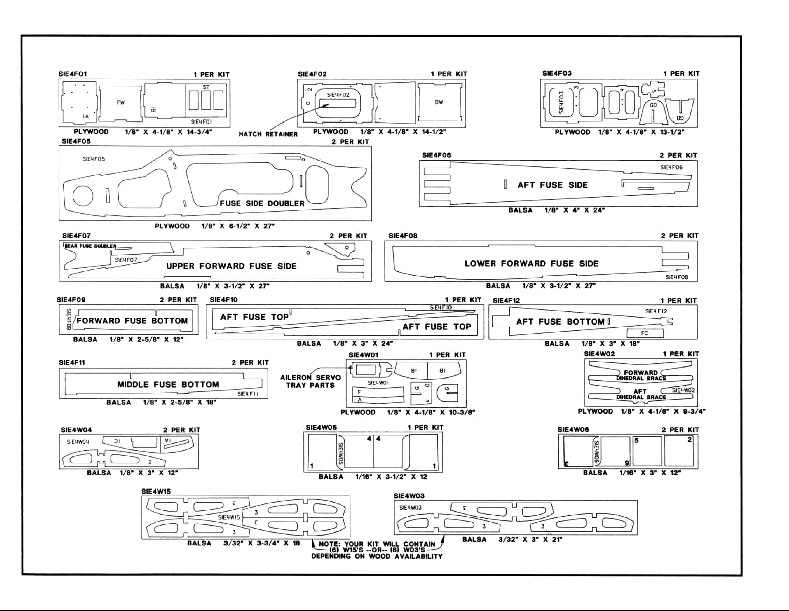
DIE PATTERNS
Page 5

5
EARLY IN THE
BUILDING SEQUENCE
ENGINE AND MOUNT SELECTION
The recommended engine size range is as follows:
.28-.40-.46 cu. in.
.40-.48-.60 cu. in. 4-cycle
NOTE: The displacement in bold type is the
most highly recommended. However, all
these engines will fly the Sierra well.
The supplied MM40 motor mount should
hold most of the two strokes in the range and
some of the four strokes. It is permissible to file
the inside of the mount slightly to fit larger engines
(see photo on page 28). Some engines may
require you to buy a different mount from your
hobby dealer. Study the plans and the engine
mounting section of this bookformore information
and sample installations.
BOLT-ON OR
RUBBER BAND-ON WINGS
The Sierra has been designed and tested
with rubber band-on or bolt-on wings. The rubber band on wings will better absorb the shocks
of a crash or landing accident such as a cartwheel.
If you have a good instructor and flying site or
already have some flying experience, you may
want to use the bolt-on wing option.
3 OR 4 CHANNELS
The Sierra flies very well with or without
ailerons. The 3-channel version will be cheaper
and easierto build. The 4-channel version offers
the extra flexibility of aileron control. Ailerons
2-cycle
of
make cross wind take offs and landings easier
to control, so many instructors recommend
ailerons.
TRICYCLE OR TAILDRAGGER
GEAR
The tricycle landing gear is considered
standard. We recommend the tricycle gear if
this is your first airplane because it offers the
best ground handling as well as straight ahead
take offs and landings. The tricycle gear also
does a better job of protecting the propeller
during bouncy take offs and landings. If you
are sport flying the Sierra or want to learn to fly
a taildragger, provisions have been made to
allow you to build the Sierra as a taildragger.
The Great Planes #L-7 tail wheel assembly
may be purchased from your dealer and
modified slightly to match the drawing on the
fuselage plans.
SELECTION OF WHEELS
The standard recommended wheels
two 2-3/4" main wheels and one 2-1/2" nose
wheel. If you are flying off grass or an uneven
surface, you may wish to use larger wheels
than those recommended. The standard
wheels have been tested off of grass and work
fine, but 3" wheels all the way around would
work even better.
If you will be flying a taildragger off of
grass, we recommend using 3" to 3-1/4" main
wheels and a 1" to 1-1/4" tailwheel.
are
OTHER ITEMS REQUIRED
Three or Four-channel radio with 3 or 4 servos
Engine
Propellers (Top Flite Power Point recommended-see
engine instructions for sizes)
2-1/4" Prop Spinner
Fuel Tank (Most 6 to 10 oz. tanks will tit)
2-3/4" Main Wheels (2)
2-1/2" Nose Wheel (1) (or 1" Tailwheel)
5/32" Wheel Collars - (4-6)
Top Flite MonoKote"
*Model shown covered with 2 rolls of Yellow, plus Missile
Red, and Orange for trim
Silicone Fuel Tubing
Latex Foam Rubber Padding (1/4" thick)
#64 Rubber Bands (10-12 for rubber band-on wings)
1/8" Foam Wing Seating Tape (optional)
SUGGESTED SUPPLIES
AND TOOLS
2 oz. Thin CA Adhesive (Hobbico Bullet Glue is Recommended)
2 oz. Medium CA Adhesive (Hobbico Bullet Glue is Recommended)
15-Minute Epoxy (Hobbico Bullet Glue is Recommended)
Hand or Electric Drill
Drill Bits: 1/16", 3/32", 1/8", 5/32", 3/16", 1/4"
Top Flite Heat Sealing Tool
Top Flite Heat Gun
Hobby Saw (X-acto Razor Saw)
X-acto Knife, #11 Blades
Pliers
Screw Drivers
T-Pins
Straightedge
Short ruler
Masking Tape (Suggested for construction)
Sandpaper (coarse, medium, fine grit)*
T-Bar Sanding Block (or similar)
Waxed Paper
Lightweight Balsa Filler
1/4-20 Tap. Tap Wrench (optional bolt on wings)
IsopropyI Rubbing Alcohol (70%)
Dremel Moto Tool or similar (optional)
NOTE: On our workbench, we have four 11" T-Bar sanders,
equipped with #80, #100, #150, and #220-grit sandpaper. This
setup is all that is required for almost any sanding task.
Sanding blocks can be made from balsa for sanding hard to
reach spots. We also keep some #320-grit wet-or-dry
sandpaper handy for finish sanding before covering
Page 6
6
COMMON ABBREVIATIONS USED
IN THIS BOOK AND ON THE PLANS:
Deg. = Degrees Lt = Left
Elev = Elevator Ply = Plywood
Fuse = Fuselage Fit = Right
LE = Leading Edge (front) Stab = Stabilizer
LG
= Landing Gear TE = Trailing
= Box to check after step " = Inches
is completed.
Edge (rear)
Save all scraps. If any of the die-cut parts are difficult
to punch out, do not force them! Instead, first cut
around the parts with an X-acto knife. After punching
out the die-cut parts, use your T-Bar or sanding block
to lightly sand the edges to remove any die-cutting
irregularities.
3. As you identify and mark the parts, separate
them into groups, such as fuse (fuselage), wing, fin
and stab (stabilizer), and hardware.
USING GLUE
There are two types of glue that are recom-
mended for building this model: CA and Epoxy.
gaps, require slight repositioning, or involve
hardwoods. Medium CA can be used to make
small fillets between parts in high stress areas.
Medium CA is a very good general purpose
glue and many people use it for the majority of
their building.
Some medium CA glues can be slow to set,
especially when used to fill gaps. A product
known as CA accelerator is available to speed
things up. It is sprayed onto the joint after the
glue is applied and chemically reacts with the
glue causing it to set very rapidly. There are a
few precautions to consider when using an
accelerator...
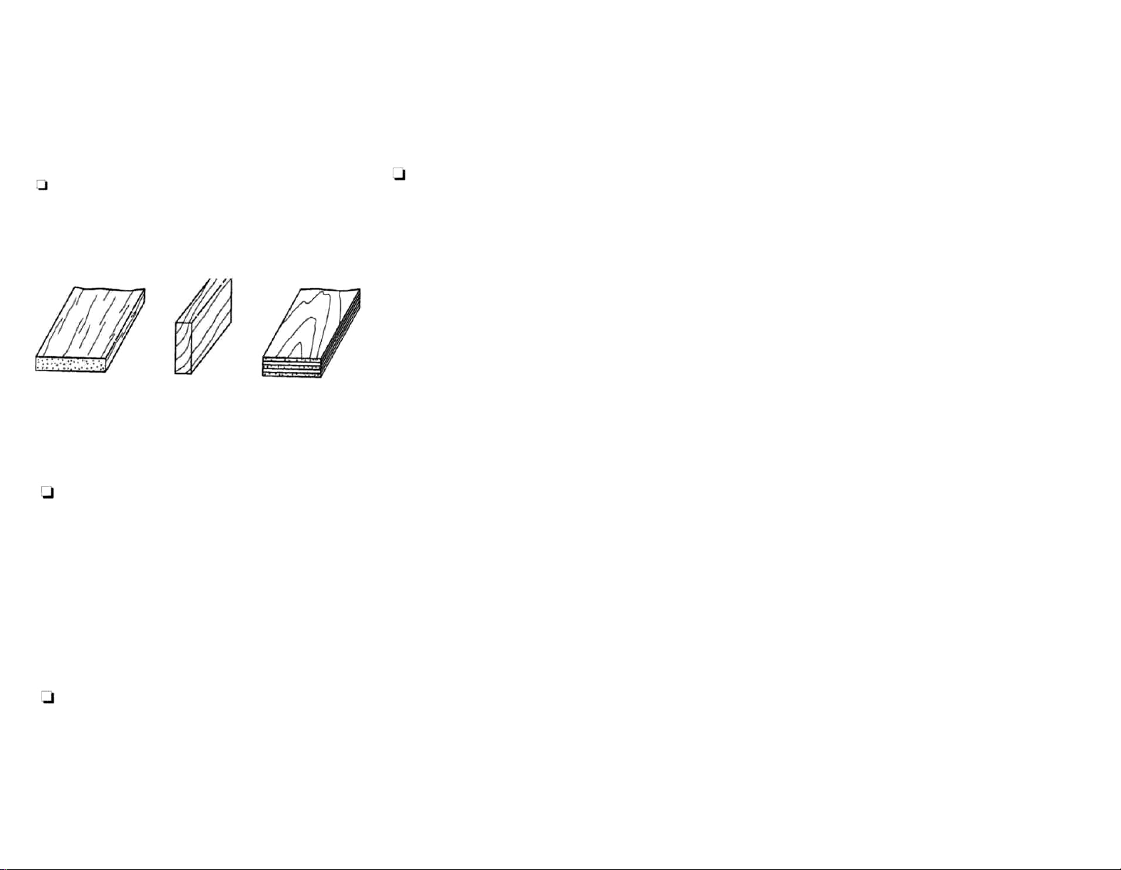
Balsa Basswood Plywood
GET READY TO BUILD
1. Unroll the plan sheets. Re-roll the plans inside
out to make them lie flat. The wing plan sheet has a
cut-line across it. If you have a small building space
you may cut the wing plan into two pieces along this
line.
The fuselage plan sheet does not have a cut-line
across it. It is used mostly for reference and not
much building is done over it. There is not much
benefit in cutting it apart, but you may do so if you
wish.
2. Remove all parts from the box. As you do,
figure out the name of each part by comparing it with
the plans, die-cut patterns, and the parts list at the
back of this book. Using a felt tip pen, write the part
name or size on each piece to avoid confusion later.
Use the die-cut patterns shown on page 4 to identify
the die-cut parts and mark them before punching out.
CA (cyanoacrylate) glue is used for general construction. It is available in a variety of
viscosities. We recommend you have the following two types.
Thin CA has a viscosity similar to water
and is used to glue together parts that fit
together very well and do not require repositioning after glue is applied. Thin CA is especially effective for gluing balsa to balsa. It can
be used to glue hardwoods such as plywood,
spruce, or bass but it is usually necessary to
fillet the joint afterwards with some medium CA.
Thin CA has the ability to "wick" into joints. This
means it will be drawn into very fine gaps
between parts. This characteristic makes thin
CA very useful for a lot of tasks, such as gluing
seams that are already clamped together or
installing CA hinges. Thin CA usually sets very
rapidly, so do not expect to move parts at all
after glue is applied. This rapid reaction may
also produce fumes and a significant amount of
heat. Always use CA glues in a well-ventilated
area.
The other type of CA glue we recommend
is medium (or gap filling). Medium CA is used
in
general construction for parts which have
Use it in a well ventilated area. The rapid
reaction can release irritating fumes at a higher
rate than normal. Do not use CA accelerator on
thin CA!
Be careful when using the accelerator
around plastics. Certain accelerators may
attack some plastics and the vapors may fog
clear canopies. It is best to test the glue and
accelerator on a scrap piece of plastic if one is
available.
Using too much accelerator may cause the
CA glue to react very rapidly and literally boil.
This will result in a joint with a chalky white color
which is not nearly as strong as a normal joint.
Epoxy is used on high-stress joints that
require toughness and vibration resistance.
Epoxy also works well in areas that may encounter fuel. Its slower cure time allows parts
to be clamped, checked, and realigned if necessary before the epoxy sets. Epoxy is available in many different formulas having different
cure times. The single best type of epoxy to
have available when building your Sierra is one
that sets in 15 minutes, but you may also find 5minute epoxy handy to have around.
Page 7
NOTES ON SANDING
1. Use a block orT-barwhereever possible when
sanding. The flat block will "ignore" glue and
changing wood density and give you a true and
even shape.
2. Always use fresh, sharp sandpaper. Sharp
sandpaper will cut through glue and hard materials easily, giving an even surface. Older, dull
sandpaper will require more pressure and may
gouge the surface.
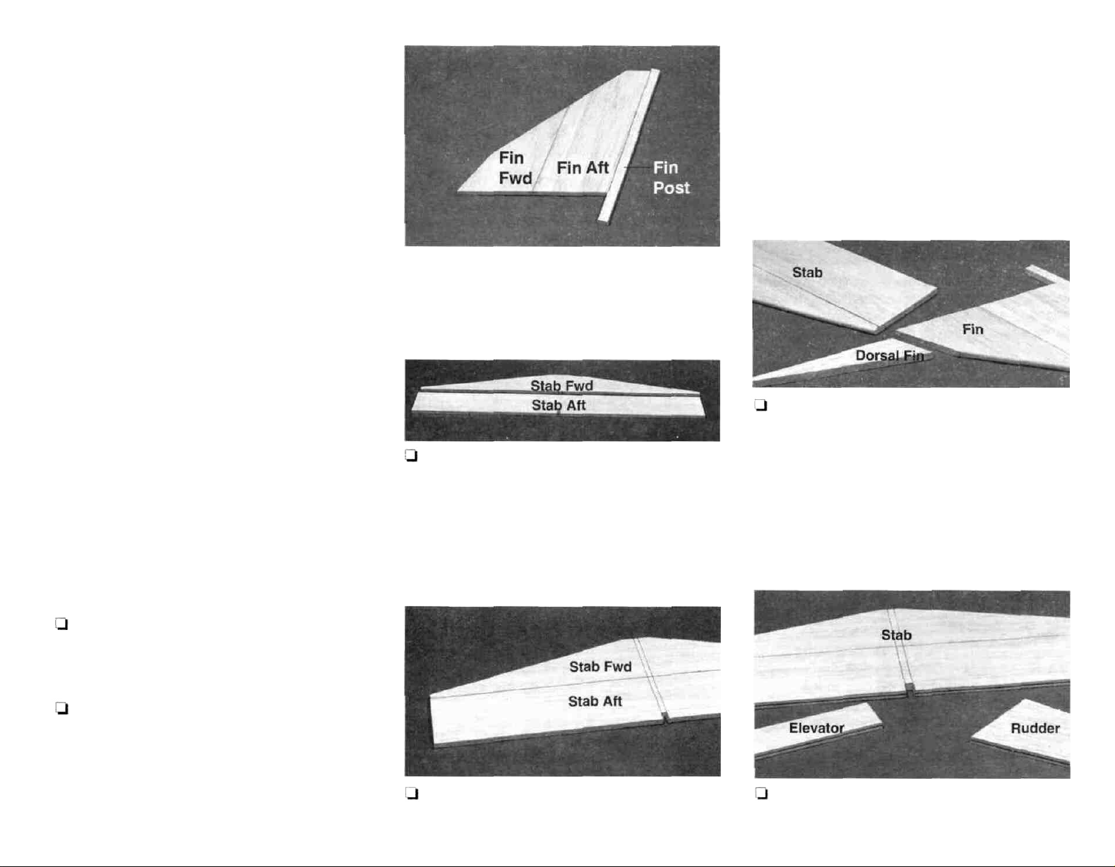
BUILD THE TAIL
SURFACES
To build the tail surfaces, you will need the following:
1/4" shaped balsa fin fwd
1/4" shaped balsa fin aft
1/4" shaped balsa rudder
1/4" shaped balsa stab fwd
1/4" shaped balsa stab aft
Tapered balsa elevator
1/8" bent wire elevator joiner
of a paper towel to make sanding easier. Flip the
parts over and apply some thin CA to the other side
of the joint.
3. The notch in the shaped 1/4" balsa stab aft
piece is positioned at the back edge of the stab so the
fin post can protrude through the notch later when
you are told to attach the tail surfaces to the fuselage.
Glue the shaped 1/4" balsa stab (stabilizer) fwd to
the stab aft in the same manner as the fin parts.
7
150 grit sandpaper to smooth out any unevenness.
Carefully block sand the edges and ends to correct
any slight bumps or mismatches. Align the notch at
the back edge of the stab and the stab TE with the
plans. Mark the fin location on the front edge of the
stab. Draw two lines from these marks to the notch
in the aft edge of the stab.
5. Refer to the cross section on the plans. Use
a sanding block to round the stab leading edge
(except the flattened center portion). Mark the
location of the dorsal fin on the forward edge of the
fin using the plans as a guide and round the fin only
above the dorsal fin. The fin, rudder, and stab should
have their tip edge corners rounded slightly for
easier covering (see the cross sections on the fuselage plans).
1. Work on a flat surface covered with waxed
paper. Refer
their
locations.
2. Put the shaped 1/4" balsa fin fwd, fin aft, and
the 1/4" x 3/8" x 8-7/8" balsa fin post together and
check how the parts fit. Block sand the mating
surfaces until they fit well. Hold the parts together
tightly and glue them together with thin CA. Imme-
diately wipe off any excess glue with a quick stroke
to the plans to identify the parts and
4. Block sand the surfaces of the fin and stab with
6. Use a smooth ball point pen to draw a
Page 8
8
centerline along the stab trailing edge, tapered balsa
elevator leading edge, fin trailing edge, and shaped
1/4" balsa rudder leading edge.
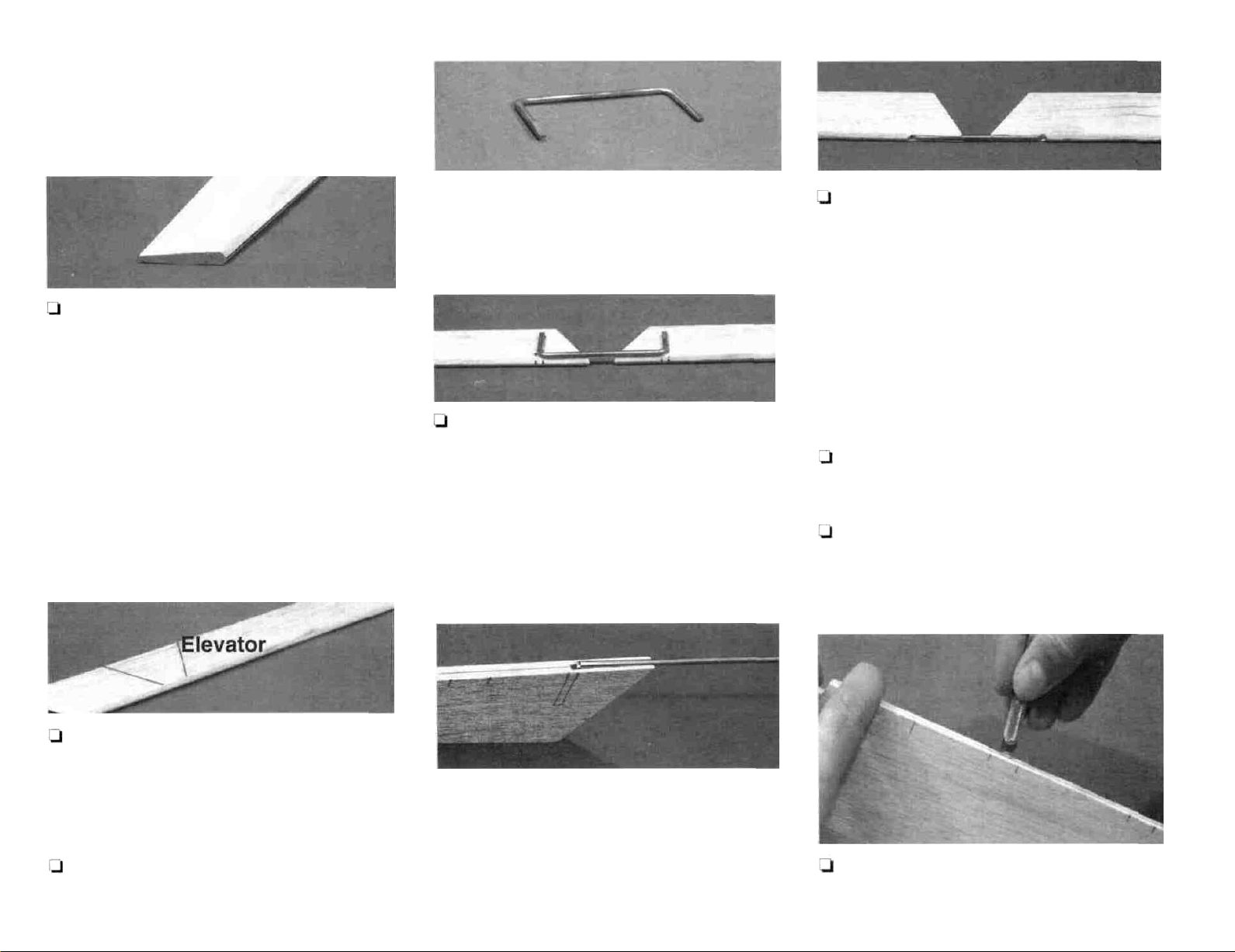
7. Referring to the cross sections on the plans,
carefully block sand the elevator and rudder leading
edges to a "V" shape. The centerlines you drew
earlier should remain for hinging later.
NOTE: The rudder may be left at a constant
thickness of 1/4" or you may taper it with a
sanding block to match the top view on the
fuselage plans. For a model that travels at a
relatively slow speed such as this one, it is not
necessary to taper the rudder to make the aircraft
fly properly. If you want to taper it for appearance
reasons, that is fine.
shown on the plans and in the photo. This will make
it easier to align the elevators.
10. Lay the elevators and the elevator joiner over
the plans. Mark where the joiner will insert into the
elevators. Start the hole in the elevators by cutting
a small 1/8" square notch with a sharp #11 knife.
Carefully drill a 1/8" hole into each elevator to the
depth shown on the plans. Use the knife to cut a
groove in the front of the elevator at the root end for
the joiner (as shown in the photo).
11. Make sure the joiner wire will fit all the way into
each elevator and that both elevators lie flat on the
work surface with the joiner installed. Bend the joiner
wire if necessary to make the elevators line up with
each other. Rough up the joiner wire with coarse
sandpaper and clean it with alcohol. Mix some 5minute epoxy and use a tooth pick or piece of wire to
push the epoxy into the hole and groove in the
elevator. Push the joiner into the elevators and wipe
away any excess glue. Lay the parts over the plans
to aid in alignment while the glue sets. It is important
that the elevator LE is straight so you will not have
problems when you hinge it later.
12. After the epoxy is cured apply some thin CA
to both sides of the balsa elevator over the joiner to
'harden' the area. Sand the cured glue smooth.
13. Place the fin and stab over the plans and mark
the hinge locations on the trailing edges. Transfer
the locations onto the elevator and rudder leading
edges.
8. Hold the tapered elevator stock over the plans
and mark the locations of the cuts at the center
where the elevator is cut away to allow for rudder
movement. Use a razor saw to cut away the right and
left elevators.
An alternate method to make a groove in a surface
for a torque rod is to sharpen the end of an appropriately sized (1/8") brass tube from the inside with a
#11 knife, then use the tube to cut out the notch for
9. Locate the bent 1/8" wire elevator joiner. Use
the torque rod.
14. Cut the hinge slots using
a flat file or a grinder to taper the ends slightly as described on the following page.
the
technique
Page 9
9
CAUTION!!! You must use extreme care to
avoid cutting yourself when cutting hinge
slots with an X-acto knife. If the balsa breaks
while you are pushing on the knife, the blade
could go into your hand before you know it!
A good precaution is to wear leather gloves
while performing this step.
A. Begin by carefully cutting a very shallow slit
at the hinge location. This first cut is to establish your
cut in the right place, so concentrate on staying on
the centerline and don't cut too deep!
B. Make three or four more cuts in the same line,
going slightly deeper each time. As you make
these additional cuts, work on going straight into the
wood. Continue this process while "wiggling" the
knife handle forward and backward until the blade
has reached the proper depth for the hinge.
C. Trial fit the hinge into the slot. If the hinge is
difficult to push in, re-insert the knife and move it
back and forth in the slot a few times to enlarge the
slot.
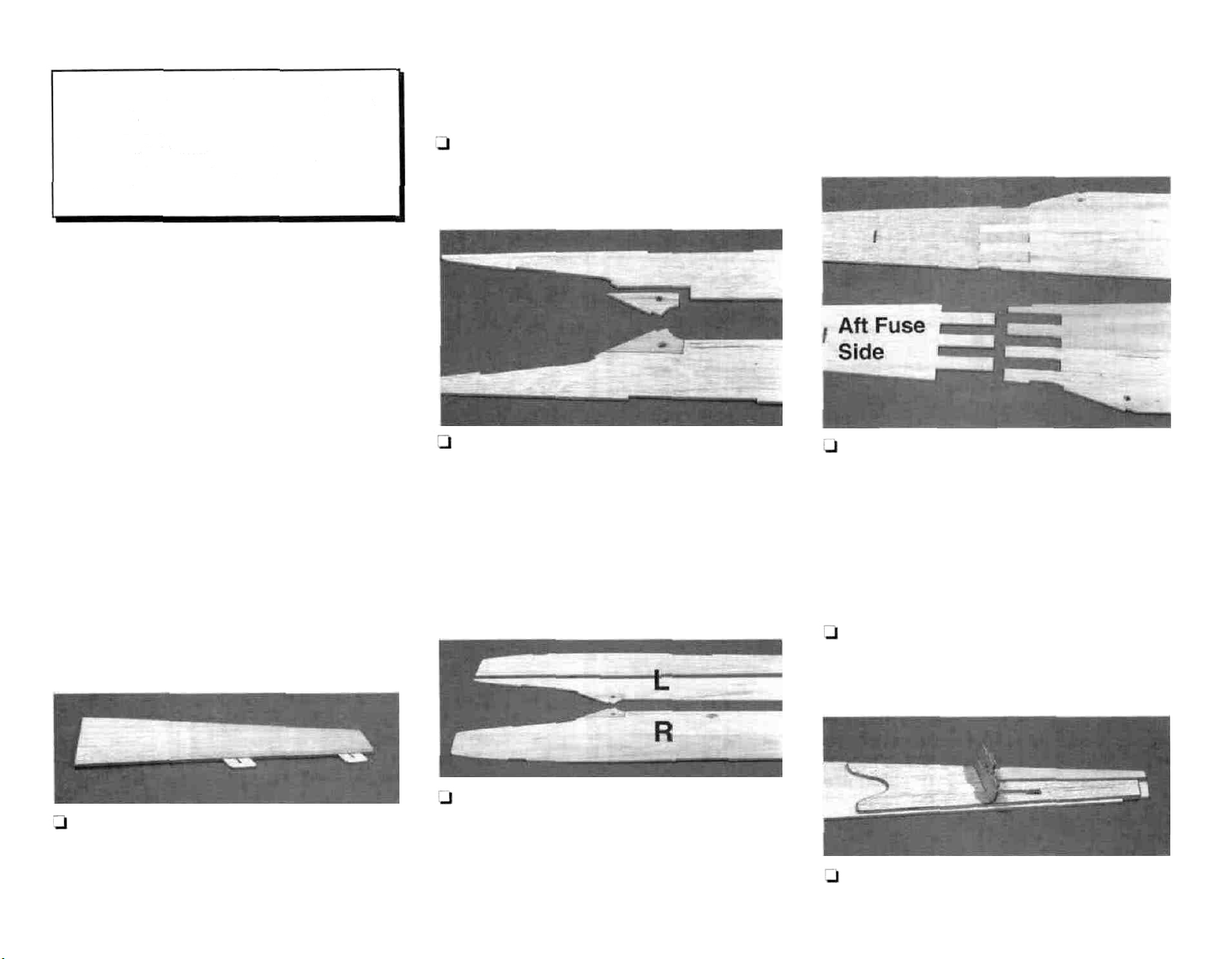
BUILD THE FUSELAGE
1. Place the fuselage plan side view on your work
table. Cover it with waxed paper.
2. Use thin CA to glue the separately die-cut
corner of the die-cut 1 /8" balsa upper forward fuse
sides in place as shown in the photo. These parts
are located in the same die-cut sheets (SIE4F07).
Remember that you will be making a right and a left
fuselage side. You may wish to glue from opposite
sides of the wood in order to reduce sanding.
NOTE: The plans may shrink or expand slightly
due to humidity. Do not worry if the parts are not
exactly the same size as the plans.
4. Plug the die-cut 1/8" balsa aft fuse sides into
the forward fuse sides. Sand them lightly if necessary to make them fit. Before gluing be sure to align
the parts over the plans. Any "bend" in the fuse sides
will cause the fuselage to twist later. When the fuse
sides are well aligned with the plans, glue the forward
and aft pieces together with thin CA. Add medium
CA to any joints that are not tight fitting.
15. Trial fit the hinges in the slots and trial fit the
rudder and elevator in place on the fin and stab. Do
not glue the hinges until after you have covered
the model.
3. Glue the upper forward fuse sides to the diecut 1/8" balsa lower forward fuse sides using thin
CA. Mark the inside surface of the fuse sides with the
letters 'R' and 'L to designate the inside of the Right
and Left fuselage sides. Be sure to make a RIGHT
and a LEFT fuselage side.
5. Use a sanding block to sand smooth all of the
joints you have made on the fuse sides.
6. Position the die-cut 1/8" balsa rear fuse
doubler in its place on the inside surface at the rear
Page 10
10
of the fuselage side. Use the die-cut 1/8" plywood
former F-5 to help you position the doubler (do not
glue the former in until told to do so later). Notice that
the pushrod exit holes do not line up (this is normal
and makes the pushrod installation in later steps
easier). Apply several beads of medium CA to the
doubler and position it on the fuselage side. When
it is aligned properly, press it firmly down to spread
out the beads of glue. Repeat this step for the other
side. Be sure to make a RIGHT and a LEFT.
carefully in position. Apply thin CA around the all
edges of the doubler to reinforce it. Glue the
doublers to the inside of both the left and the right
fuse sides.
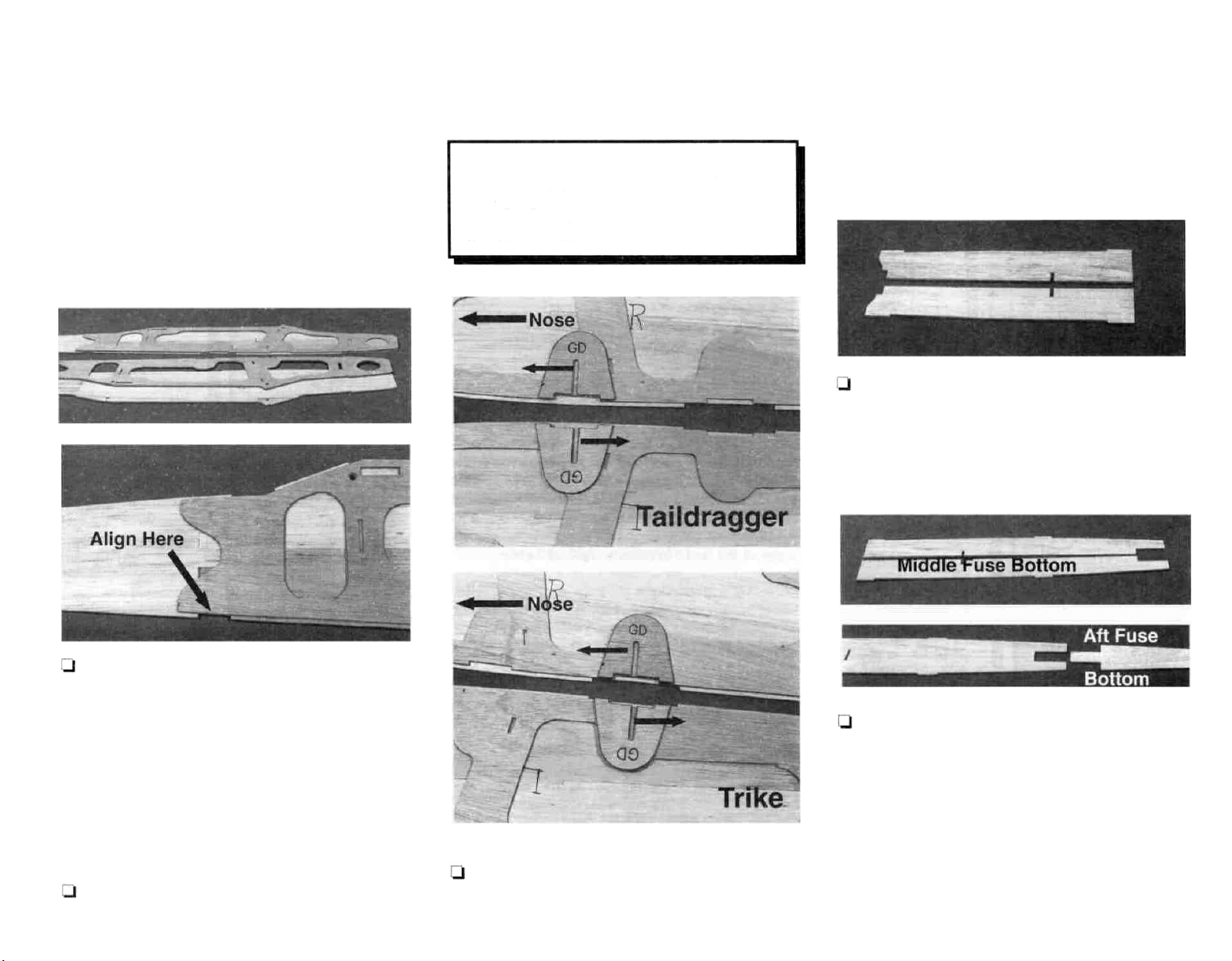
AT THIS POINT YOU MUST DECIDE
WHETHER YOU ARE GOING TO BUILD
A TAILDRAGGER OR A TRIKE GEAR
MODEL. THE POSITION OF THE LANDING
GEAR DOUBLER (GD) DEPENDS ON THIS.
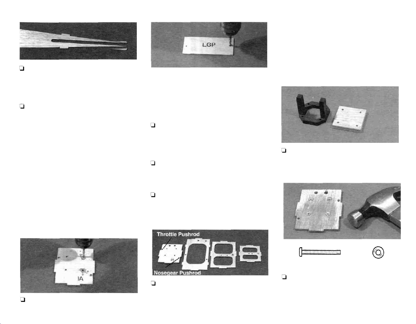
may be placed in two different positions (forward for
taildragger gear, aft for trike gear). Note also the offcenter slot in the doubler. The slot should be offcenter toward the aft end of the left fuselage side,
and the forward end of the right fuselage side. Glue
the gear doublers in the position chosen.
10. Glue the right and left die-cut 1/8" balsa
forward fuse bottom pieces together with thin CA.
Add medium CA to any gaps.
fuselage doubler over the inside of the fuselage
sides. Notice that it should fit perfectly at the very
front of the fuselage, and then be offset 1/8" in from
the edge of the fuselage sides most of the rest of the
way back. The photos and plans will help you
determine the proper location of the doublers. Use
the front edges and the lock notch in the fuse side
near the lower aft portion of the doubler to align the
doubler.
8. Apply medium CA to the doubler and press it
9. Study the fuselage plans in the landing gear
area. The die-cut 1/8" plywood gear doublers (GD)
11. Glue the right and left die-cut 1/8" balsa
middle fuse bottom pieces together with thin CA.
Place the die-cut 1/8" balsa aft fuse bottom piece
into the notch at the back end of the middle fuse
bottom. Notice that there is a gap in the middle. This
is for former F-4 to key into later. Check that these
parts are properly aligned by positioning them over
the fuselage top view on the plans. Glue with thin
CA. Add medium CA to any gaps.
Page 11
12. Glue the right and left die-cut 1/8" balsa aft
fuse top pieces together with thin CA. Note the diecut "bumps" at the aft end of the aft fuse top. Trim
these off with a straightedge and a sharp knife.
13. Use medium CA to glue the die-cut 1/8"
plywood firewall F-1A (1A) to F-1B (1B). F-1A is
centered on the slightly larger F-1 B. Make sure the
side of F-1A with the punch marks on it remains
visible. (See the photo at step 14).
NOTE: For the following steps, refer to the firewall
cross section drawing on the fuselage plans. At this
point you must know which engine you will use. If you
are using a recommended 2-cycle engine which fits
into the supplied mount, all the punch marks on F-1A
will be drilled to their appropriate size (in the following
steps). If you are using a 4-cycle engine or an engine
that requires a different mount, you will need to
determine the mounting, throttle pushrod exit, steering
pushrod exit, and fuel line exit hole locations for your
installation. (HINT: Use the four standard mount
punch marks on F-1A to help you locate an alternate
mount by drawing an "X" between them to find the
engine centerline). Regardless which engine you are
using, mount it on this centerline.
drill. Use the firewall (F-1) cross-section on the
fuselage plans to positively identify these hole locations. While you have the 5/32" drill bit out, drill 5/32"
holes through the two punch marks in the die-cut
1/8" ply landing gear plate (LGP).
15. Drill 1/4" fuel line exit holes at the top edge
of F-1. The punch mark locations should be OK for
most engine installations.
16. Drill a 3/16" throttle pushrod hole in F-1 in the
location you determined. A punch mark indicates
the "standard" pushrod exit location.
17. If you are using the tricycle landing gear, drill
a 3/16" pushrod exit hole in F-1 at
the
appropriate
punch mark location.
11
NOTE: At this point you should determine if you
need to use the 9mm x 2" x 2" plywood spacer
plate in your engine installation. Study the
engine installation drawings on the fuse plan
sheet. Short engines such as the OS .40 FP
require the use of this plate. Longer engines
such as the OS .40 SF or 4-cycle engines do not
require the use of this plate.
19. If you are using the 9mm spacer plate, center
the MM40 motor mount on one side of the plate and
mark the four mounting hole locations. Drill the holes
in the spacer plate with a 1/8" drill bit.
14. If you are using the supplied mount, drill the
four punch marks in the middle of F-1 with a 5/32"
18. Drill 3/16" pushrod holes at the punch marks
in die-cut 1/8" plywood formers F-2 (2), F-3 (3), and
F-4 (4). Refer to the cross-sections on the fuselage
plans to confirm the pushrod locations.
4-40 x 1" Machine Screw No. 4 Flat Washer
20. Gently tap the 4-40 blind nuts into the back
(F-1 B) side of the firewall. Bolt the motor mount (and
the 9mm spacer if required) to the firewall using the
supplied 4-40 x 1" machine screws and
#4
wash-
ers. Carefully apply a small drop of thin CA to the
Page 12
12
perimeter of the flange on each 4-40 blind nut.
Remove the motor mount.
1/8" plywood former F-5 (5) in place to confirm a
good fit.
IMPORTANT NOTE: All formers (F-1 through
F-5) are glued in with the stamped numbers
facing forward and upright as shown in the
photos. This is necessary to maintain proper
pushrod routing.
21. Use a small round file to blend the pushrod
exits at the aft end of both the fuselage sides to allow
the outer pushrod tubes to exit at the proper angle
as shown on the fuselage top view and in the photos.
If you do not have a file, use a #11 knife to shape the
pushrod exits as shown in the photo. Hold die-cut
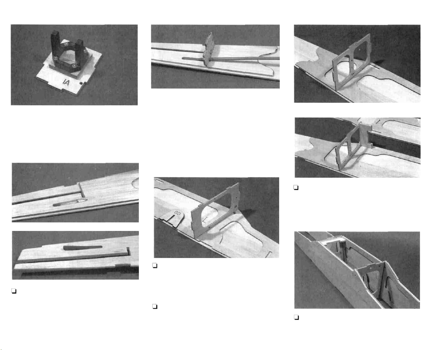
22. Use medium CA to glue the die-cut 1/8"
plywood former F-2B to the left fuselage side. Use a
90 degree triangle to keep the former perpendicular
to the fuse side while gluing.
23. Glue the die-cut 1/8" plywood former F-3 to
the left fuse side in the same manner as F-2. (The
photo for this step is at the top of the next column).
24. Push the 1 /4" ply wing bolt plate into position
just ahead of F-3 but do not glue yet. If the fit of this
plate is too tight, sand it slightly till it fits comfortably.
(Install this plate for strength even if you are using
rubber band-on wings.)
side structure. When all the alignment tabs on F-2
Page 13
and F-3 are thoroughly engaged by the right fuselage side, turn the fuselage upright as shown in the
photo and apply medium CA glue to the joints of the
right fuse side and F-2 and F-3.
26. See the photo above step 29 for the proper
position and orientation of the die-cut 1/8" plywood
former F-4. Use medium CA to glue former F-4 in its
place between the fuselage sides. Snap the die-cut
1/8" plywood former F-5 into position at the back of
the fuselage but do not glue yet; instead, use some
masking tape to hold the fuselage together. Re-
member all of the former I.D. numbers face forward.
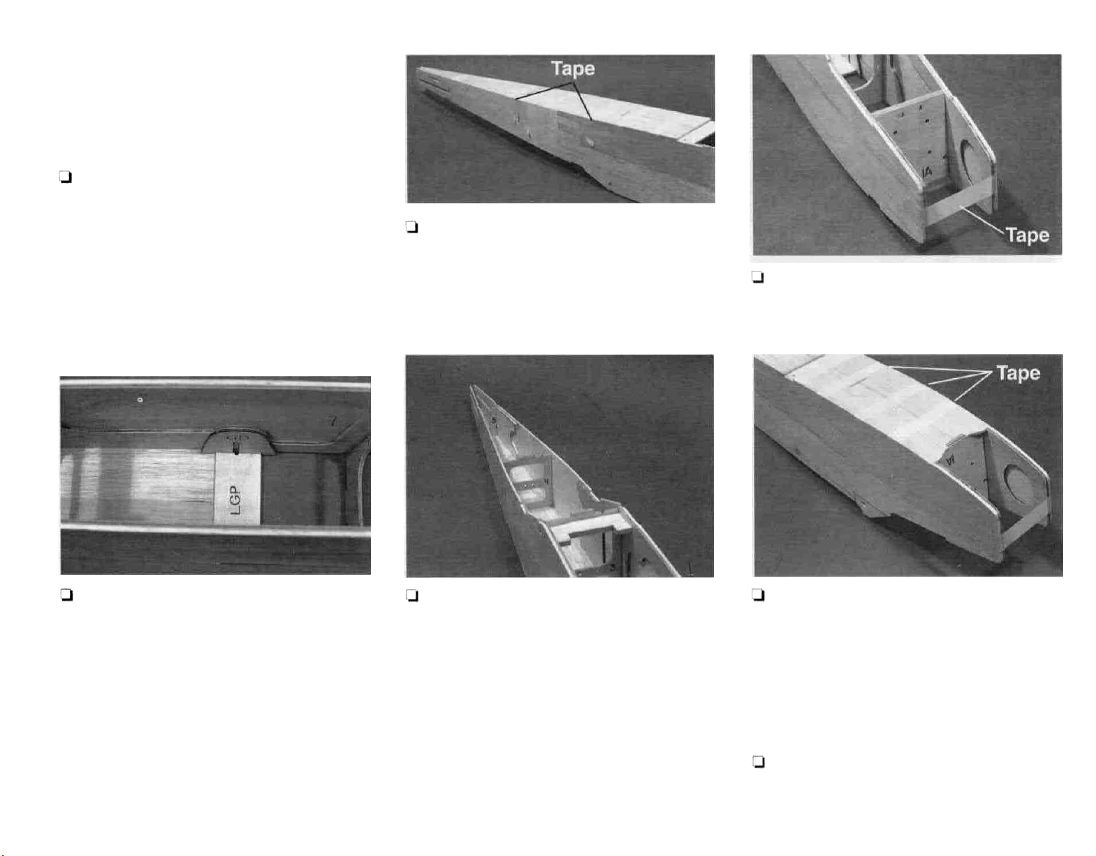
28. Work the aft fuselage bottom pieces (assembled earlier) into position between the fuselage
sides, sanding if necessary for a good fit. Use some
masking tape to hold the fuse together.
13
30. Position the firewall (F-1A/B) in place between the fuselage sides. Use a strip of masking
tape to hold the fuse sides together at the front. Do
not glue the firewall yet.
27. Snap the landing gear plate (LGP) into
position at the fuse bottom. If you are building a
taildragger, make a duplicate of LGP (but without the
holes) out of scrap 1/8" balsa and substitute it at the
tricycle LGP location. The plywood LGP will be
installed in step 31 for the taildragger. Check to see
that the holes for the landing gear line up with the
slots in the gear doublers (GD). Do not glue yet.
29. Check the previously assembled, unglued
parts for fit and alignment. Correct any problems.
Apply medium CA from the inside of the fuselage to
any unglued joints involving the following parts: F-3,
F-4, F-5,and LGP. Use thin CA to glue the fuse
bottom to the fuse sides from its front edge back to
F-5. The very aft portion will be glued later when the
tail surfaces are installed.
31. (If you are making the taildragger version, put
the 1 /8" plywood LGP in place between the fuselage
sides at the taildragger position shown on the fuselage plans.) Work the 1 /8" forward fuse bottom sheet
joined earlier into position between the fuselage
sides. Use masking tape to hold the fuse bottom in
place.
32. Flex the fuselage sides outward and apply
medium CA or epoxy to the edges of the firewall.
Use
masking tape to hold the joint closed while the
Page 14
14
glue cures. Glue the forward bottom sheeting to the
fuse sides, the firewall, LGP, and former F-2 with thin
CA followed with a fillet of medium CA.
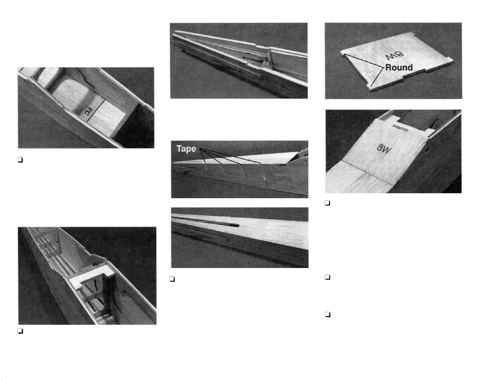
33. Glue the die-cut 1/8" balsa fuselage cross
member (FC) to the forward bottom sheeting as
shown on the fuse plan side view. This piece simply
stiffens the fuselage floor in the tank area.
rudder and elevator pushrods. Glue them securely
to the fuselage sides, F-5, F-4, and F-3.
34. Sand the outside of two of the 24" outer
pushrod tubes so glue will stick to them. Work
these into position as shown on the plans for the
35. Snap the previously joined aft fuse top into
place on top of the fuselage. Use masking tape to
hold the fuse top in place. Wick thin CA glue into its
joints with the fuse sides and the formers. Do not
glue the area behind F-5 yet. Remove the tape and
run thin CA down the joints again to make sure they
are thoroughly glued.
36. Trial fit the die-cut 1 /8" plywood back window
(BW) in its place on the fuse top. Refer to the
fuselage side view; for best results, bevel the fore
and aft edges of the window to provide a better fit.
HINT: To eliminate difficult sanding later, round the
"lock tabs" on the outside edges of the plywood
windows to a radius similar to that shown on the plan
cross-sections before gluing the windows in.
37. Glue the back window in with thin CA. Then
add some medium CA if required.
38. Wick thin CA into all joints involving the wing
bolt plate. After this has cured, apply a fillet of epoxy
or medium CA around the wing bolt plate.
Page 15

39. Round the outside of the "lock tabs" on the
die-cut 1/8" plywood front window (FW) as you did
on the back window. Fit the front window into place.
Glue with thin and medium CA. You may round the
corners of the fuselage to match the cross sections
as you go, or you may wait until the fuselage is done.
40. Sand the edges of the die-cut 1/8" plywood
fuel tank hatch till they are smooth. Test fit the
hatch in place. Trim the hatch or trim back the notch
in the front of the fuse side doublers until the hatch
fits well. Round the right and left edges of the hatch
to a radius like that shown in the firewall (F-1) cross
section.
No. 2 x
15
the LGP to allowthe main landing gearto be installed
(as shown on the fuselage plans). The pre-cut 1/8"
x 9/32" x 3-3/4" plywood LG aligner strips are the
same ones used for the tricycle gear. Fill the gap in
the 1/8" balsa bottom sheeting at the tricycle gear
location with scrap 1/8" balsa.
44. Test fit the wire main landing gear into the
holes in the fuse bottom. In orderforthe landing gear
to lie flat on the bottom of the fuse, it is necessary to
remove a little material from the inside edge of the
5/32" holes to allow for the bends in the wire. Do this
with a round file or a knife.
3/8 Sheet Metal Screw
41. Use CA to glue the die-cut 1 /8" plywood hatch
retainer tab to the inside of the hatch as shown in the
photo and on the fuse side view.
42. The punch marks in the front of the hatch
indicate the location of the No. 2 x 3/8" sheet metal
screws used to hold the hatch on. Check to make
sure these will direct the screws into the firewall.
Tape the hatch in place on the fuselage. Drill a 1/16"
hole through the punchmarks into the firewall. Remove the hatch and enlarge the holes in the hatch
only to 3/32". Screw the hatch down with the sheet
metal screws to confirm a good fit.
43. If you are building a taildragger, you need to
cut a gap in the forward fuse bottom sheeting under
45. Put the two bent wire main landing gear
pieces in place on the fuselage bottom. Slide the
pre-cut 1/8" x 9/32" x 3-3/4" plywood LG aligner strips
in place fore and aft of the main landing gear. Sand
the edges of the strips if necessary for a good fit.
Glue these strips in place with medium CA, being
careful not to glue in the landing gear wires.
Page 16

16
No. 2 x 3/8 Sheet
Metal Screw
46. Put the main landing gear back in position and
place two molded nylon landing gear straps over
the wire LG as shown in the picture. Mark, then drill
four 1/16" pilot holes. Use four No. 2 x 3/8" sheet
metal screws to hold down the LG straps. The
landing gear may be removed until after covering.
Nylon Landing Gear Strap
This completes the basic construction of the
fuselage.
BUILD THE WING
is a very flat board that you can pin into. "Celotex,"
a type of board you can find at a hardware store or
home center, is an example of one). Cover the left
wing panel section with waxed paper so you won't
glue the wing to the plan.
2. Assemble the wing guide tool from the die-cut
1/8" plywood pieces marked "G". The "0" degree
(from vertical) side of the tool can be used to check
the ribs to see if they are vertical. The "4" degree
side will be used later. Do not glue the tool to-
gether.
3. The shaped and notched balsa leading edges
and trailing edges are joined by a thin layer of balsa.
These are cut apart in one of two ways:
A. Break the pieces apart and clean up the
rough edges with a sanding block.
-OR-
Xacto knife
Hold knife at an angle
when cutting apart
LEADING EDGE
B. Carefully run a knife down the edge between
the parts to cut them cleanly apart.
NOTE: The Sierra was designed to use
symmetrical leading and trailing edges (they
have no top or bottom). They do, however, have
a root end and a tip end.
4. The tip ends of the leading and trailing edges
are the ends with a notch very close to the end. Mark
the leading and trailing edges with a "T" to designate
the tip. T-Pins
T-Pins
NOTE: The SIERRA wing, much like the fuse, is
designed so all the major components can be fit
together without glue. This allows you to check
that the pieces are properly fit and aligned before
applying glue to the joints. The wing plan may
be cut in half along the line provided if you wish.
1. Tape the LEFT WING PANEL portion of the
plan over your work surface. (The best work surface
Spar
Work Surface
5. Use the criss-cross pin technique shown in
the illustration to pin a 3/8" x 3/8" x 30" balsa spar
over its location on the plans. Pin the spar in 3 or 4
places. (The photo for this step is at the top of the
next column)
Page 17

17
TWO WARPED SPARS INSTALLED
THIS WAY WILL RESULT IN A
STRAIGHT WING
TWO WARPED SPARS INSTALLED
THIS WAY WILL RESULT IN A
WARPED WING
Photo for Step 5
6. Remove the wing ribs
R-1's,
R-2's, and
R-3's from the die-cut sheets. Slide twelve 3/32"
balsa R-3 ribs into place on the bottom spar.
8. Insert the back of the ribs into the notches
in the trailing edge.
NOTE: The plans may shrink or expand slightly
due to humidity. Do not worry if the parts are not
exactly the same size as the plans.
9. Adjust the positions of the leading and
trailing edges left or right until the ribs line up with the
plans. Pin the leading and trailing edges tothe board
so they won't move.
11. Insert the 3/8" x 3/8" x 30" top spar into the
notches in the ribs.
12. Make sure all the R-3 ribs and the leading
and trailing edges are resting on the flat work surface. Make sure the ribs are inserted all the way into
the notches. The "guide tool" is used to check that
the ribs are vertical.
7. Insert the front of the ribs into the notches
in the leading edge. Remember to orient the LE with
the
"T"
at
the tip.
10. Lay two pieces of scrap 1 /16" balsa (from
the die-cut center section sheeting SIE4W05 or
SIE4W06) near the leading and trailing edges under
the location of rib R-2 (this will shim up the rib to allow
for the sheeting later). Push rib R-2 into place as
shown on the plans. Make sure the ends of the rib
engage the notches in the leading and trailing edges.
13. Apply thin CA to all the joints involving the
ribs, spars, leading edges, and trailing edges.
NOTE: When gluing the spars to R-2, make sure
the spars are centered between the dihedral
brace notches in R-2.
14. Remove the pins holding the spar in place
but leave the panel pinned flat on the board by the
leading and trailing edges.
Page 18

18
17. Position the 4 deg. side of the guide tool
exactly where the end of the bottom spar is shown on
the plans. Use a pen to mark an angled line on the
top and bottom spars.
ends of the spars and leading and trailing edges
flush with the outermost R-3 rib.
If you are building the 3-channel wing (without
functioning ailerons), follow the instructions in
the shaded box. If you are building the 4-channel
wing, skip to step 24.
15. With the panel held flat on the table, use
medium CA to glue in the pre-cut 1/16" x 1-1/2" x2"
balsa shear webs between the R-3 Ribs. Refer to
the plans. Notice there are shear webs on both
sides of the spars outside the first two R-3 ribs and
only behind the spars between the remainder
of
the R-3's.
NOTE: The function of the shear webs is to keep
the spars from collapsing. They will not and need
not touch or be glued to the ribs. They should be
thoroughly glued to the spars.
16. Make sure the wing panel is still lined up
properly over the plan.
18. Use the guide tool to mark angled lines
on
the leading and trailing edges from where their
bottom ends are shown on the plans.
19. Use a razor saw to cut off the spars and the
leading and trailing edges at the marked angles. A
T-bar is used to "clean up" the angled ends of the
spars, leading edges, and trailing edges.
20. Use a razor saw and a T-bar to trim the tip
NOTE: The LEFT WING PANEL plan and its
cross-sectional view show the "no aileron"
version.
Page 19

19
21. The 17/32" x 1-1/2" x 30" tapered
balsa aileron stock fits against the trailing
edge stock with its lower surface flat on the
table. Glue the aileron stock to the trailing
edge of the wing. (See the photo on the
previous page.)
22. Trim the tip end of the aileron stock
flush with the end of the wing.
23. Trim and sand the root end of the
aileron to match the 4-degree angle of the TE
and spars.
SKIP TO STEP 27
to the wing trailing edge at the tip as shown on the
RIGHT WING PANEL drawing. (This is done to the
right and left wing.)
26. Trim and sand the aileron stock flush with
the tip of the wing.
MAKE THE WING TIPS
27. Look at the FRONT VIEW of the wing on
the plans to see the proper orientation of the 15/32"
x 1-5/8" x 11-1/4" tapered balsawingtips. Thesmall
end of the taper is positioned at the bottom edge of
the wing.
it to final shape. HINT: Put masking tape over the
surrounding structure when sanding items such as
the wing tips to protect areas you don't want sanded.
REPEAT STEPS 5-29 OVER THE
RIGHT WING PANEL PLANS TO
BUILD THE RIGHT WING.
JOIN THE WING
24. Carefully cut a 1-5/8" long piece off the
17/32" x 1-1/2" x 30" tapered balsa aileron stock .
25. Glue the 1 -5/8" long piece of aileron stock
28. Hold the wing tip up to the end of the wing.
Trace the top of the airfoil onto the wing tip. Saw or
carve the wing tip to the rough shape of the wing,
leaving it slightly oversized.
29. Glue the wing tip to the wing. Block sand
braces. Put reference marks at the center of the
braces. NOTICE: The dihedral brace with the "lock
bumps" for the aileron servo tray is positioned on the
aft side of the spars (these bumps may be trimmed
off if you are not using ailerons).
31. Test fit the two wing panels together with the
dihedral braces in place. Check to see that the
spars, leading edges, and trailing edges match up
well. Make adjustments if necessary.
The dihedral angle (the angle at which the wings
are "bent up") is not considered critical. This
angle is established by aligning the spars with
Page 20

20
the dihedral braces. For your reference, if one
wing panel is resting flat on the table, the other
wing tip should be approximately 4" off the table.
32. Look ahead to the photos with steps 33 and
34 for a view of the joined wing. Spread a layer of 15-
minute epoxy onto the matching surfaces of the
dihedral braces and the LEFT wing panel spars.
Align the dihedral braces with the top and bottom
edges of the spars. Clamp or tape the braces in
position until the glue sets.
NOTE: If there are any small gaps between the
ends of the spars or LE's or TE's, do not be
overly concerned. They will not significantly
weaken the structure. After the wing joining
process is complete, fill them with scrap balsa
and medium CA glue.
34. The die-cut 1 /8" plywood forward center brace
(F) is glued in next. It should be centered on the
leading edge so the 1/16" balsa top and bottom
center sheeting will lap onto it. Align the left and right
leading edges and glue the brace in place with CA or
epoxy.
36. Glue the two die-cut 1/8" balsa R-1A's (1A)
together to form a 1/4" thick part. Glue the two diecut 1/8" R-1C's (1C) together to form a 1/4" thick
part.
37. If you are using the bolt-on wing option, draw
two lines forward from the slot in R-1A as shown in
the photo, for later reference.
33. When the epoxy is set, apply a thin film of
epoxy to the dihedral brace and the right wing
spars, slide the two wing panels together, and
carefully align the spars with the dihedral braces.
After the epoxy is cured, if any of the dihedral brace
joints do not appear to be thoroughly glued, apply an
extra fillet of epoxy to them.
35. The die-cut 1 /8" plywood aft center brace (A)
is centered on the trailing edges. Align the left and
right trailing edges and glue the brace in with CA or
epoxy (if you are building the 3-channel version, the
fixed aileron stock should be aligned and glued
together at this time).
NOTE: If you are building the 3-channel version,
do not punch out the cutout for the aileron servo
in R-1C. Instead, glue it permanently in place.
Punch it out as shown in the photo at the top of
the next column for the 4-channel version.
38. Use medium CA to glue R-1C in place. It is
centered to allow for the top and bottom center
section sheeting as shown in the cross-section
drawing beside the right wing panel.
39. Put R-1A in place as shown in the cross
Page 21

section. If you are using rubber band on wings, glue
it with CA. If you are using bolt on wings, transfer the
marks from R-1A onto the forward center brace (F)
and remove R-1A.
DO STEPS 40 - 49 FOR
BOLT ON WINGS
40. Draw a vertical center line on the forward
center brace.
21
45. Cut away the material in front of the slot
in R-1A to allow the dowel to pass through the
front of the wing into the slot.
42. Use the R-1 cross section on the wing
plan to determine where the dowel will exit the
leading edge, and mark this location. Drill a 1/
8" pilot hole from the front of the wing through
this mark, then through the previously drilled
pilot hole in the forward center brace.
41. Drill a 1/8" pilot hole into the forward
center brace (see the photo). The angle of this
hole will obviously not be correct, so you need
not go all the way through the balsa leading
edge. Just go through the plywood.
43. Gradually increase the size of the drill
until you reach 1/4". Test fit a 1/4" wing dowel
through the hole.
44. Replace R-1 A and glue with medium CA.
Remember that it is centered vertically to allow
for the 1/16" sheeting.
46. Insert a 1/4" dowel into the leading edge
and push it all the way into the slot. Put a mark
on the dowel 1/2" ahead of the leading edge of
the wing. Remove the dowel and cut it at the
mark. Round the end of the dowel slightly to
allow easy wing mounting.
47. Glue the dowel in place with thin CA.
Page 22

22
48. Test the fit of the die-cut 1 /8" plywood R1 B's (1 B) against the R-1 A's. Trim the Ft-1 B's
if necessary for a good fit. The dowel may also
need to be flattened slightly with a sanding block
to allow the R-1 B's a good fit.
49. Glue in the R-1 B's with 15-minute epoxy.
Photo for Step 51
53. Sand the root ends of the tapered and
grooved balsa trailing edge center pieces so
they will meet properly when they are held
together against the TE. Mark the parts so you
can identify the bottom of the left and right parts.
50. For rubber band on wings, glue the die-cut
1/8" plywood R-1 B's to the R-1 A's, forward center
brace (F), and dihedral brace with epoxy.
DO STEPS 51 - 62 IF
INSTALLING AILERONS
51. Cut out and remove the remaining
piece of balsa from across the servo bay in the
bottom side of R-1 C using a knife or razor saw
(see photo at top of next column).
52. Snap the die-cut 1/8" plywood aileron
servo tray and servo tray support in place as
in the photo. Use medium CA to glue in the
servo tray support while using the servo tray to
hold it in position. Do not glue the servo tray in
at this time.
54. Hold the trailing edge center pieces over
the right wing panel plan. Mark where the
torque rods will exit the bottom of the trailing
edge. The root cross-section gives a view of the
cut-out. Cut a notch in the trailing edge center
pieces to allow the torque rod to exit.
55. Hold the trailing edge center pieces up
to the wing. Transfer the notch locations onto
Page 23

23
the wing. Use a knife to cut small notches into
the wing TE.
56. Use coarse sandpaper to roughen the
nylon tube on the bent wire aileron torque rod.
Slide the tube toward the threaded end of the
rod. Apply a small amount of petroleum jelly to
the ends of the nylon tube to prevent glue from
wicking into the bearing tube.
57. Assemble the parts as shown in the
photo. Apply a small amount of medium CA to
glue the torque rod bearing tube to the balsa
trailing edge center.
60. Following the instructions on page 8,
step 10 for installing the elevator joiner, transfer
the location of the aileron torque rods onto the
ailerons. Drill a 3/32" hole into each aileron to
accept a torque rod. Notch the front edge of
each aileron to accept the rest of the torque rod.
bar to sand the front edge of the ailerons to a "V"
shape to match the cross section on the plans.
WING CENTER SECTION SHEETING
63.
Lightly write the identity (1-6) of each piece
of die-cut 1/16" balsa wing sheeting using the cut
patterns on page 4 as a reference. Remove the
individual sheets from the blanks.
WRONG
RIGHT
58. Use medium CA to glue the trailing edge
center assemblies to the trailing edge of the
wing. Do not get glue in the bearing tube.
59. Trim the left and right tapered aileron
stock pieces to length so they fit between the
wing tip and the center pieces with about a 1/16"
gap at each end.
61. Draw a center line on the LE of the
ailerons and the trailing edge of the wing, use
the plans as a reference to mark the location of
the hinges. Make slots for the hinges using the
same technique as you did for the elevator and
rudder.
62. Use a razor plane (if available) and a T-
64. Pieces 1, 2, and 3 form the top wing skins;
4,
5, and 6 form the bottom wing skins. Over waxed
paper, glue the 2's and 3's together to form a left and
a right top aft wing skin (as shown in the photo). Glue
the 5's and 6's together to form a left and right bottom
aft wing skin.
Page 24

24
65. Fit the pieces 5-6 in place behind the spar on
the bottom of the wing. Cut a notch to go around the
aileron servo tray support if present. Glue the wing
skin in place.
and cut out a slightly oversized opening for the
aileron servo.
68.
Fit the forward bottom wing skins (4) to the
wing, and glue in place.
70. Sand the joints in the center of the
a block and sharp 220 grit sandpaper.
wing with
FINAL ASSEMBLY
1. Fit the wing on the fuselage wing saddle. Trim
the aft edge of the wing trailing edge at the center
with a sanding block if necessary for a good fit.
66. If you are using ailerons, cut a couple of 1/4"
wide strips from scrap 3/32" balsa, glue them in as
shown in the photo to stiffen the bottom wing skin
where the servo cut-out will be made.
67. For planes with ailerons, snap the aileron
servo tray in position and trace the shape of the cutout on the bottom wing skin. Remove the servo tray
69. Fit and glue on the top wing skins (1 and 2-
3).
ELONGATE HOLE
IF NECESSARY
NOTE: For bolt on wings, the wing dowel hole in
F-3 may be oblonged some if required to let the
wing sit flat on the saddle or to allow for wing
seating tape. If the hole requires oblonging, do
so with a round file or a #11 knife.
2. Remove the wing from the fuselage. Mark a
centerline on the 1/16" x 1-7/8" x 5-1/2" plywood
Page 25

4. Drill two 3/16" pilot holes through the
trailing edge plate and wing TE at the intersection of the lines. Be sure to drill perpendicular
to the surface of the trailing edge plate.
25
the photo) in the slot at the back end of the fuse.
Put a pin vertically into the piece on the fuselage
centerline. Attach a length of string to the pin.
Use the string to check if the wing is on straight
(see diagram).
trailing edge plate.
to cut about 1/2 way through the plate on the center-
line. Bend the plate away from the cut until it starts
to break. Place the plate on top of the wing, and
adjust if necessary. Glue the plate to the wing with
medium CA.
Use a knife and a straightedge
DO THESE STEPS FOR
BOLT ON WINGS
3. Referring to the right wing plan. Mark a
line 5/8" from the trailing edge. Mark two lines
1-3/8" from the wing centerline as shown.
Both distances must
be equal!
B=B
A=A
5. Place the wing on the fuselage. Pin a
piece of scrap 1 /4" balsa (or the fin as shown in
6. Once the wing is straight, use some
masking tape hold it in place. Drill through the
3/16" pilot holes perpendicular to the trailing
edge plate and through the wing bolt plate in
the fuselage with a #10 (or 13/64") drill.
7. Remove the wing and re-drill the holes in
the wing only to 1/4" or 17/64".
8. Use a 1/4-20 tap and a tap wrench to cut
threads in the plywood wing bolt plate.
Page 26

26
9.
Harden the threads in the wing bolt plate
with thin CA glue, then re-tap the threads after
the glue has completely hardened.
1"
1/4-20x2" Nylon Bolt
two inch portion of the stab/fuse junction only. Re-
move the fin. Thoroughly glue the forward two
inches of the stab to the fuselage from the inside
(through the fin slot) and outside (do not go all the
way back to the aft end of the fuse until you are told
to). Be sure to also glue the stab to former F-5.
Photo for Step 1
2. Temporarily slide the fin into place. Check the
fit of the parts. The bottom edge of the fin should rest
on the stab.
10. Cut approximately 1" off the threaded
portion of the 1 /4-20 x 2" nylon wing bolts. Bolt
the wing onto the fuselage.
If you are using rubber band on wings, temporarily
slide the dowels into the holes in the fuselage
sides (enlarge the holes in the fuselage with a
round file if the fit is too tight). Align the wing and
attach it with several # 64 rubber bands.
MOUNT THE TAIL SURFACES
1. Slide the horizontal stabilizer (stab) into its slot
in the fuselage. Align the stab by looking down at the
stab reference lines through the fin slot in the upper
aft fuse sheeting. Put a couple of marks on the stab
outside the fuselage sides for reference after the
vertical fin (fin) is installed. (The photo for this step
is at the top of the next column)
CORRECT
INCORRECT
3. Sight the alignment of the fin and stab from the
front and back of the model with reference to the
wing. Also sight the fin and stab from the top to check
alignment. Make adjustments to the fuse slots if
necessary so the surfaces are not twisted or skewed.
4. Put a small amount of thin CA on the forward
5. Apply a generous bead of medium CA to the
bottom edge of the fin and to the fin slot in F-5. Slide
the fin into the slot in the fuselage. Check the
alignment to make sure the fin is not leaning. Also
glue the fuse joints at the top corners.
6. Wick thin CA into any remaining fin, stab, and
fuselage joints that are not thoroughly glued. Be
sure to flip the fuselage over and glue all stab, fin
post, and fuselage joints from underneath.
Page 27

7. Sand the joints at the back of the fuselage
smooth. For a nice touch, sand the outer pushrod
tubes flush as shown in the photo.
9. Slide the elevator into position using its hinges
to support it (do not glue the hinges yet.) Slide the
rudder into its place. Mark the location where the
elevator joiner contacts the rudder. Cut and sand a
notch in the rudder large enough so the elevator
joiner wire and the rudder do not contact each other
when the surfaces are moved through their range of
motion.
27
11. If you use a Great Planes L-7 tailwheel
wire, modify it slightly as shown on the fuselage
plan sheet.
Photo of completed tailwheel.
12. Drill into the rudder at the location shown
on the drawing with a 3/32" drill to allow the tail
wire to be inserted into it. Notch the LE of the
rudder to accept the nylon bearing. Harden the
bottom portion of the rudder around the tail wire
with thin CA before covering.
NOTE: Do these steps after the model is
covered with Monokote.
8. Round the top edge of the shaped 1/4" balsa
dorsal fin. Use the seam on the top of the fuselage
to help you center the dorsal fin. Glue it on with thin
CA followed by a small fillet of medium CA.
DO STEPS 10-14 IF YOU ARE
BUILDING A TAILDRAGGER
NOTE: Refer to the tailwheel section on the
fuselage plans for details and drawings.
10. You may make a tail wire from scratch
or purchase a Great Planes L-7 tail wire from
your hobby dealer.
13. Place a small amount of petroleum jelly
at both ends of the nylon bearing to keep glue
out. Use a toothpick to push glue into the 3/32"
hole in the rudder. Insert the tail wire and wipe
away any excess glue.
14.
Roughen the forward tab of the nylon
bearing and epoxy it into the fuselage during the
hinging process.
Page 28

28
MOUNT THE ENGINE
See the ENGINE AND MOUNT SELECTION section
on page 5 for additional information.
STALLATION OF AN IRVINE 40 ON THE SUPPLIED MOUNT.
NOTE: The assembly and installation of the fuel
tank and fuel lines is covered on page 36-37. You
may assemble and trial fit your tank while
installing the engine.
3. To determine the best fore and aft position of
your engine on the engine mount, install the spinner
on the engine. Using the plans as referance, place
the engine on the engine mount so that the spinner
is the same distance from the fuselage. Mark the
location of the mounting bolts and drill the holes with
a 7/64" (or #36) drill. NOTE: If you have access to a
drill press, use it for drilling these holes to insure they
are drilled vertically (See previous photo).
THIS PHOTO SHOWS THE INSTALLATION OF AN
OS .40 FP ON THE SUPPLIED MOUNT.
1. Study the different drawings on
plans that show engine installations.
that matches your installation closest.
2. You should already have determined if you
need to use the 9mm spacer plate during fuselage
construction. Use it as required.
NOTE: If the engine mount supplied in the kit
does not appear to fit your engine (example OS
40 SF), you may have to file the corners of the
engine mount rails to make room for the
crankcase. (See sketch and photo.)
File corners of
rails to fit your
Flat File
the fuselage
Find the one
engine
MM40
Mount
4. Mount the engine with the four #6 x 3/4" sheet
metal screws. (An alternate method is to drill the
holes with a #43 drill, tap them 4-40, then mount the
engine with 4-40 x 3/4" socket head cap bolts, not
included).
5. Remove the muffler and needle valve (if
necessary) from the engine. Bolt the engine and
mount to the fuselage. Determine if any cutouts are
necessary for the needle valve or muffler (see the
photos for ideas). Mark any cutouts that are required.
THIS PHOTO SHOWS THE INSTALLATION OF AN
OS .48 SURPASS ON A DAVE BROWN 60 FS
MOUNT. THIS MOUNT MAY BE PURCHASED
FROM YOUR HOBBY DEALER. IT MAY BE
DRILLEDTOINSTALLTRICYCLE LANDING GEAR.
THE FOLLOWING SEQUENCE SHOWS THE IN-
File Corner
NOTE: It is best to remove the engine before
cutting out clearance holes, but at least plug the
carburetor intake and the exhaust output port
before making dust.
Page 29

DO THESE STEPS FOR
TRICYCLE LANDING GEAR
29
8. One 5/32" wheel collar is pressed into the
nylon steering arm; then the 6-32 x 3/16"
machine screw is threaded in. This assembly
is used below the mount. The other 5/32" wheel
collar and the 6-32 socket head screw are used
above the mount to retain the nose gear. Assemble the parts as shown to determine the
location of a flat which will be made under the 632 x 3/16" machine screw. Disassemble the
parts.
6. Cut out any clearance holes or notches you
marked in the previous step. Mount the muffler.
7. If you are building a trike gear and are not
using the 9mm spacer, you will need make an
indentation into the firewall to provide clearance for the nylon steering arm. Mark the
location of this cutout under the mount. After
the mount is removed, relieve the area enough
to clear the steering arm (a Dremel Moto-Tool
is handy for this job).
NOTE: The steering arm is rotated away
from the firewall when the axle is aligned for
straight ahead steering. Refer to the photos
and plans for proper orientation.
9. Clamp the wire nose gear in a vise and use
the side of a flat file to make a flat spot at the
location you marked.
Page 30

30
FINISHING
BALANCE THE
AIRPLANE LATERALLY
SPECIAL NOTE: Do not confuse this procedure
with "checking the C.G." or "balancing the airplane fore and aft." That very important step will
be covered later in the manual.
Now that you have the basic airframe nearly
completed, this is a good time to balance the airplane
laterally (side-to-side). Here is how to do it:
1. Temporarily attach the
muffler) to the fuselage.
wing and engine (with
fore, before covering, you should make a final check
of the entire structure. Fix any dents with a lightweight filler, then sand the entire structure smooth
using progressively finer grades of sandpaper. Sand
major areas to be covered using MonoKote" with
#320 sandpaper just before covering
HINT: Small dents in balsa wood can often be
swelled back out by applying a small drop of water to
them.
COVERING
Follow the instructions included with your
covering material. Thoroughly read through
them before beginning.
MonoKote, and alcohol will remove them later (for
some tasks, you may be able to put your marks on
the backing where they will not need to be removed).
A metal straightedge and a sharp knife are great
tools to have around for cutting MonoKote.
2. With the wing level, lift the model by the engine
propeller shaft and the aft end of the fuselage (this
may require two people). Do this several times.
3. If one wing always drops when you lift, it means
that side is heavy. Balance the airplane by gluing
weight to the other wing tip. NOTE: An airplane
that has been laterally balanced will track better
in loops and other maneuvers.
FINAL SANDING
Carefully examine your fuselage comparing the
"corners" with the cross sectional drawings on the
plans. Sand (using a block where possible) the
corners of your fuselage until they match those
shown on the plans.
Nearly every imperfection in your wood structure will show through the covering material; there-
TIPS FOR COVERING WITH MONOKOTE:
Make copies of the 2 view drawing on page 44 of this
manual and use it to plan your trim scheme.
When covering surfaces with corners, cut the mate-
rial as shown to allow it to fold up and cover the
corners without gaps or bumps.
Precut strips for covering objects such as elevators.
A permanent marker will put reference marks on
When covering with Monokote® the top and bottom
of the stab, and the sides of the fin, allow about 1/8"
to 3/16" of covering to lap onto the fuselage as in the
photo.
Page 31

Cover the tips of the ailerons before the bottom and
top.
Recommended Covering Sequence:
1. Rudder left side
2. Rudder right side
3. Bottom of elevators
4. Top of elevators
5. Stab bottom
6. Stab top
7. Fin left side
8. Fin right side
9. Fuse bottom
10.
Fuse sides
11.
Fuse top
12.
Fuel tank hatch
13.
Ends of ailerons
14.
Bottom of ailerons
15.
Top of ailerons
16.
Wing TE plate
17.
Bottom of left wing
18.
Bottom of right wing
19.
Top of left wing panel
(overlap covering 1/4" at
20.
Top of right wing panel
(overlap covering 1/4" at the LE)
panel
panel
wing LE)
31
3. Fuel proof any external exposed wood.
MonoKote matching brush on Chevron Perfect Paint
works nicely here.
HINGING
NOTE: CA Hinges are hinges made specifically
to be used with CA glue. These hinges have a
plastic core which is laminated with fibers to
allow the CA to adhere to them.
(using
CA
hinges)
Cover the wing TE Plate before the rest of the wing.
NOTE: DO NOT, under any circumstances,
attempt to cut the covering material after it has
been applied to the fin and stab, except around
the leading and trailing edges and the tip.
Modelers who do this often cut through the
covering and part-way into the balsa stab. This
can weaken the stab to the point where it may fail
in flight!
When covering concave surfaces, follow the
with a damp cloth, pressing the covering down.
iron
FUEL PROOFING
1. Fuel proof the firewall area and the engine
compartment. Black K&B epoxy paint was used for
this on one of the prototypes. Thirty minute epoxy,
polyester resin, or polyurethane-based paints will
also work here.
2. Fuel proof the inside of the fuselage forward
of F-2. K&B polyester resin and a bent epoxy brush
were used for this on the prototypes. 30 minute
epoxy also works well for fuel proofing.
1. Find the slots you made earlier. Open them up
by cutting a small rectangle of MonoKote away with
a sharp X-acto knife.
NOTE: Keep a folded tissue handy to absorb any
thin CA that may drip onto the MonoKote by
accident. Any glue residue can be completely
removed with CA Debonder
Page 32

32
2. Push the hinges half way into the control
surfaces. Wick several drops of thin CA into the slot
from both sides of the hinges.
3. Fit the elevator and rudder onto the airframe.
Make sure that all of them fit and line up properly.
Wick several drops of thin CA into the hinge slots on
the elevator, then the rudder. Be sure to glue the
hinges in from both sides of the surface.
RIGHT WRONG
mark the location of the mounting holes. Drill 3/32"
mounting holes through the marks. Then wick some
thin CA glue into them to 'harden' the balsa. The
horns are screwed in place using 2-56 x 5/8" ma-
chine screws and nylon nut plates.
throttle use horns made out of large, "four armed"
horns. The aileron horn is set up to provide "differential throw." In this case it will cause the ailerons
to deflect "up" more than they deflect "down." The
horn shown is made out of a large, round Futaba
horn that is drilled on the "1" and "4" radial lines
where they intersect the "12.5mm" radius line. (See
the drawing on the wing plan).
4. Make the rudder and elevator pushrods: Cut
ten 5/16" lengths of the inner pushrod tube to act as
spacers. Distribute these on the 34" threaded end
.074" wire pushrods as shown on the fuselage top
view. Note: If the spacers are extremely tight on the
.074 wire, you may cut them down to 3/16". If the
spacers are loose on the .074 wire, use a tiny drop of
CA to glue them to the .074 wire. In any case, they
should not easily move on the wire.
4. Use a toothpick to push 15-minute epoxy into
the torque-rod holes in each aileron. Fit the aileron
in place. Then glue in the hinges using the technique
described above.
FINAL CONTROL HOOKUPS
2 - 56 x 5/8 Machine Screw
Nut Plate
Small Control Horn
1. Install the elevator and rudder small nylon
control horns in line with the pushrod exits as
shown on the plans. Hold the horns in position and
2. Mount the servos into the main servo tray
oriented as shown on the fuselage plan top view.
Mount the aileron servo (if used) in the aileron servo
tray.. Since the main servo tray is adjustable fore and
aft for small CG corrections, do not glue it in until told
to do so.
3. For easy setup and good control response, we
recommend you start off using servo horns resembling those shown on the plans. The rudder and
5. Screw the nylon clevises well onto the ends
of the pushrods, insert the pushrods into their guide
tubes, and temporarily hook the clevises up to the
control horns. The pushrods will later be marked
removed so you can make the z-bends.
and
Page 33

AILERON HOOKUP
6. Cut away the bottom wing skin as shown
to provide an aileron lead exit. Use medium CA
to glue the aileron servo tray (with servo) in its
place as shown on the plans.
33
with tape and putting marks on the pushrods
even with the holes in the servo wheel.
NOTE: When attaching the Z-bends to the
servo wheels, you'll need to use a 5/64" drill
to enlarge the holes in the servo wheels.
Make the Z-bends as shown in the following
sequence.
Nylon Swivel Clevis Nylon Swivel
7. Hook up the nylon swivel clevises to the
nylon swivels. Thread a 12" threaded end
into each swivel clevis. Screw these assemblies onto the aileron torque rods down to the
height shown on the "Cross Section At
Centerline: (See the photo at step 9.)
8. Mark the locations for the Z-bends in the
aileron pushrods by holding the ailerons neutral
rod
9. Hook up and make final adjustments to
the
aileron linkage.
Page 34

34
10.
Mount the wire main landing gear. Install your
wheels and tires using wheel collars (not included)
as shown on the plans.
11.
Mount the engine, muffler, and nose gear.
Temporarily put all the equipment, such as the fuel
tank, receiver, battery, etc., in place so you can do a
preliminary Center of Gravity check to determine the
location of your servos.
12.
Put the main servo tray on its shelf and mount
the wing. Check the center of gravity using the
technique described on page 37 "Balance Your
Model". First decide whether the receiver and battery will go under the fuel tank or under the wing in
front of the servos. Then slide the servo tray fore and
aft to fine tune the balance.
NOTE: Most 2-cycle installations will require the
equipment to be positioned forward.
14. Remove the nylon clevises from the aft end
to the pushrods. Remove the pushrods. Make the
Z-bends at the servo end of the wire and reinstall the
pushrods from the front through the fuel tank hatch.
15. Make the nose wheel steering pushrod (if
required) from half of the 36" double threaded end
rod and half of the remaining 24" outer pushrod tube
(see the fuselage plans and photos for details). The
nose wheel steering pushrod uses a nylon clevis on
its servo end. Make a 90 deg. bend in the steering
arm end of the pushrod as shown on the fuselage
plans. The nose wheel and throttle pushrods do not
require spacers made from inner pushrod tube.
of
the nose wheel steering pushrod (the photos
plans show typical throttle pushrod installations).
17. Install the switch harness in the location you
desire. The prototype switch location can be seen in
the photos. Always install your switch on the opposite side of the muffler to keep it away from the oily
exhaust residue.
We recommend the following CONTROL
SURFACE THROWS:
and
13. Glue in the main servo tray with medium CA.
Mark the locations for Z-bends on the elevator and
rudder pushrods.
NOTE: See the aileron hookup section for a
description of how to make a Z-bend.
16. Make the throttle pushrod from the remainder
Some radios have adjustable travel volumes (ATV). This feature allows the user to
electronically adjust the travel of the control
surfaces. Most low cost radios used in trainers
do not have this feature so we will describe the
"mechanical" method here.
More Throw
(Continued on next page)
Page 35

35
More Throw
Move the linkages in the direction shown by the
arrows to increase the throw of that surface.
Move the linkages in the opposite direction to
decrease the throws. Always configure the
linkages toward the outside of the horns when
possible. This will tend to reduce the amount of
slop that adds up.
NOTE: Throws are measured at the widest
part of the elevators, rudder, and ailerons.
ELEVATOR: NORMAL ....1/2" UP 1/2" DOWN
(High Rate) 5/8" up
5/8" down
(Low Rate) 3/8" up
3/8" down
RUDDER: NORMAL ... .7/8" RT 7/8" LFT
(High Rate) 1" right
1"left
(Low Rate) 3/4" right
3/4" left
AILERONS: NORMAL ... .9/16" UP 3/8" DOWN
(High Rate) 5/8" up
7/16" down
(Low Rate) 3/8" up
1/4" down
NOTE: "Dual Rates" is a feature on some
radios which allows you to switch the control
surface throws in flight. This allows you to
change the responsiveness of your aircraft depending on what maneuvers you are doing. If
your radio does not have "dual rates", then set
up the control surfaces to move at the NORMAL
throws. The SIERRA can be safely flown with
any of the control surface throws listed above.
The higher throws just offer a little quicker
response.
APPLY TRIM
The main pictures show a Sierra covered in Mono-
Kote yellow, red, and orange. Another attractive
option, as shown on the side panel, is covered in
MonoKote jet white, pearl red, and pearl copper.
NOTE: This section gives an overview of how we
often trim our models. Some of the techniques
may seem slightly advanced for beginners, but
they are not really difficult.
NOTE: We use standard MonoKote for almost all
of the trim on our models. "Trim sheets" are not
completely fuel proof, and over time they will
begin to peel up. MonoKote is very thin and
lightweight. When ironed on, it wilt almost never
come off. MonoKote has the added advantage of
being able to go over compound curves since it
is applied with heat.
1. Patterns are provided in dashed lines on the
plan sheets. You may wish to trace these so you do
not destroy the plans. Only one pattern is required
to make the left and right trim pieces using the
technique described here.
NOTE: The better the quality of the cutting board
you use, the better your results will be.
2. The model is first covered completely in its
base color.
3. Choose a piece of trim to start with... for
instance, the forward stripe on the stab. Securely
tape an oversized piece of normal MonoKote,
backing side down, to your cutting board. Tape
another piece of MonoKote, backing side up, on top
of the first piece (this one will be for the opposite side
of the stab).
4. Cut the pattern from the plan sheet, leaving a
healthy border around the lines where possible.
5. Tape the pattern over the MonoKote-covered
cutting board (an alternative is to use a spray glue
such as 3M-77 to hold the pattern to the MonoKote
backing).
6. Always use a very sharp knife and enough
pressure to cut through all of the layers of covering
in
one
stroke.
7. Use a straightedge to cut all of the
straight
lines first.
8. Next, free hand cut all of the
curved
sections.
9. Separate the trim pieces and clean up any
snags or
mismatches.
10. Use the dashed lines on the plans to locate
the trim on the aircraft. Apply the trim in the same
way as normal MonoKote, but reduce the tempera-
ture some to reduce the occurrence of air bubbles.
11. Repeat this process for all of the trim.
Page 36

36
APPLY DECALS
NOTE: The decal sheet does not give you
everything you need to completely trim your
model, but it does provide all the difficult items.
B. Use a couple of small pieces of masking tape
to hold the side windows in their position on the
fuselage.
C. Use a permanent fine tip marker, such as a
"Staedtler Lumocolor 313 Permanent" avail-
able at art and drafting stores, to lightly mark
the location of the front window. Mark the
location of the aft edge of the side windows for
future reference.
D. Remove the side windows. Peel the backing
off the front window and stick it to the fuselage,
aligning it with the marks you made at the front
window location.
NOTE: These were put under the fuel tank in the
prototypes as shown on the plans. Additional
foam was put between them and the fuel tank to
hold the fuel tank at the proper height. The
position of the battery and receiver may be
changed to balance the aircraft. There is plenty
of room under the wing ahead of the servos for
the receiver and battery if necessary.
NOTE: If it is necessary to install the receiver
and/or battery in the compartment under the
wing, glue a piece of scrap balsa over the top of
their foam padding to keep them securely in
place.
1. Study the plans and the photos on the
determine where to place the decals.
2. Thoroughly clean your airplane before apply-
ing
decals.
3. Cut out the individual decal items and apply
them in the appropriate locations. NOTE: Certain
decals are provided which you may use at your
discretion, such as the "TOP FLITE" logo and the
small "SIERRA" decals.
4. The following sequence is recommended
applying the
A. Carefully cut out the windows with a sharp
knife allowing about a 1/16" border. Use a
sharp X-acto knife and a straight edge to trim
the decal edges that will lap together at the
fuselage corners exactly at their edges.
NOTE: Do not cut the side windows apart.
Applying them as a single piece will allow
you to keep them lined up with each other.
window decals:
box to
for
E. Peel the backing off the side windows.
Carefully align them with the front windows and
the marks you made for the aft edge of the side
windows.
F. When both side windows are in place, peel
the backing off the back window. Align it with
the side windows and stick it in place.
HINT: Use a fine tipped permanent marker to
blend away any slight mismatches or gaps.
HINT: You may carefully apply some thin CA
to the window lap joints with a toothpick to
prevent them from peeling up.
INSTALL THE RECEIVER
AND BATTERY
1. Wrap your receiver and battery in plastic
bags, followed with foam rubber.
2. Install the
fuselage.
battery and receiver
in the
4. Route the receiver
lowing ways:
A. Route the antenna along the inside of the
fuse side and out of the fuse top, just behind
the wing. Anchor the antenna to the top of the
fin with a rubber band.
B. Install another "pushrod guide tube" along
the inside of the fuse, along the bottom,
exiting just ahead of the rudder. Insert the
antenna through the tube, and leave the
excess length trail behind.
NOTE: DO NOT EVER CUT YOUR RECEIVER
ANTENNA OR ATTEMPTTO FLY A MODEL WITH
THE ANTENNA FOLDED OR COILED UP. THESE
CONDITIONS WILL DRASTICALLY REDUCE THE
RANGE OF YOUR RADIO.
antenna
in one of the fol-
INSTALL THE FUEL TANK
1. Assemble the fuel tank as per the manufacturer's
instructions. Be sure the "clunk" cannot contact the
back wall of the tank and interrupt the fuel flow.
Page 37

37
2. The tank should be mounted as high in the fuel
tank compartment as is practical. Use foam rubber
to surround the tank on all sides and hold it in
position.
NOTE: There is a fitting on the muffler of most
model engines (especially 2-cycles) known as a
"muffler pressure tap". When the vent line from
yourfuel tank is attached to this fitting, it supplies
the fuel tank with a mild amount of air pressure.
This pressure provides a more consistent flow of
fuel to the carburetor. The result of using this
"muffler pressure tap" is usually an engine that
will run properly whether the plane is climbing,
diving, upside-down, or right-side-up.
3. Route the fuel line from the clunk to the
carburetor fuel intake. Route the fuel line from the
tank vent to the muffler pressure tap, or leave it open
if no pressure tap is available.
NOTE: The fuel system should be completely
free of kinks or leaks. Any of these will cause the
engine to run erratically or not at all.
1. Accurately mark the balance point on the
bottom of the wing on both sides of the fuselage.
The balance point is shown on the plan (CG), and is
located approximately 3-3/4 inches back from the
wing leading edge (1/8" inch back from the center of
the spar). This is the balance point at which your
model should balance foryourfirst flights. Later, you
may wish to experiment by shifting the balance up to
5/16" forward or back to change the flying characteristics. Moving the balance forward may improve
the smoothness and provide arrow-like tracking, but
it may then require more speed for take off and make
it more difficult to slow down for landing. Moving the
balance aft makes the model more agile with a
lighter and snappier "feel." In any case, do not
balance your model outside the recommended
range.
2. With the wing attached to the fuselage, all parts
of the model installed (ready to fly), and an empty
fuel tank, position the model with the stabilizer level.
3. Lift the model at the CG marks. If the tail
drops when you lift, the model is "tail heavy" and you
must add weight* to the nose for balance. If the nose
drops, it is "nose heavy" and you must add weight*
to the tail for balance. NOTE: Nose weight may be
easily installed by sticking strips of lead into the
engine compartment beside the engine. Tail weight
may be added by using "stick-on" lead weights,
available from your hobby dealer.
*lf possible, first attempt to balance the model by
changing the position of the receiver and battery. If
you are unable to obtain good balance by doing so,
then
it will be necessary to add weight to the nose
or tail to achieve the proper balance point.
RADIO SET-UP
FOUR CHANNEL AIRCRAFT
Transmitter
Stick Movement
See
the
following page for 3 channel set up.
2. Adjust your pushrod hookups as necessary to
provide the proper control surface movements as
listed on page 34. Make sure all of the clevises are
securely "snapped" together.
Control Surface
Movement
Elevator moves up
Right aileron moves
UP and Left aileron
moves DOWN
Rudder moves
LEFT
Carburetor wide open
BALANCE YOUR MODEL
NOTE: This section is VERY important and must
not be omitted! A model that is not properly bal-
anced will be unstable and possibly unflyable.
FINAL CHECKS
1. Make sure the control surfaces move in the
proper direction as illustrated in the following
sketches.
*NOTE: These control surface "throws" are
approximate and provide a good starting point
for the first flights with your Sierra. You may wish
to change the throws slightly to provide the
smoothness or quickness that you prefer.
Page 38

38
RADIO SET-UP
THREE CHANNEL AIRCRAFT
Transmitter
Stick Movement
3. Make sure none of the pushrods are binding.
4. Make sure all of the screws and bolts on your
model are tight. Check to see that all of the servos
are secure and all of the servo wheels are screwed
on firmly.
PRE-FLIGHT
CHARGE THE BATTERIES
Follow the battery charging procedures in your radio
i
nstruction manual. You should always charge your
Control Surface
Movement
Elevator moves up
Rudder moves right
Carburetor wide open
transmitter and receiver batteries the night before
you go fly i ng, and at other times as recommended by
the radio manufacturer.
FIND A SAFE PLACE TO FLY
The best place to fly your R/C model is an AMA
(Academy of Model Aeronautics)-chartered club field.
Ask your hobby shop dealer if there is such a club in
your area and join. Club fields are set up for R/C
flying, which makes your outing safer and more
enjoyable. The AMA can also tell you the name of a
club in your area. We recommend that you join the
AMA and a local club so you can have a safe place
to fly and also have insurance to cover you in case
of a flying accident. (The AMA address is listed on
the front cover of this instruction book).
If a club and its flying site are not available, you
need to find a large, grassy area at least 6 miles away
from any other R/C radio operation, like R/C boats
and R/C cars, and away from houses, buildings and
streets. A schoolyard may look inviting, but it is too
close to people, power lines and possible radio
interference.
GROUND CHECK THE MODEL
If you are not thoroughly familiar with the operation of R/C models, ask an experienced modeler to
check to see that you have the radio installed correctly and that all the control surfaces do what they
are supposed to. The engine operation must also be
checked and the engine "broken in" on the ground by
running the engine for at least two tanks of fuel.
Follow the engine manufacturer's recommendations for break-in. Check to make sure all screws
remain tight, that the hinges are secure and that the
prop is on tight.
RANGE CHECK YOUR RADIO
Wherever you do fly, you need to check the
operation of the radio before each flight. This means
with the transmitter antenna collapsed and the receiver and transmitter on, you should be able to walk
at least 100 feet away from the model and still have
control. Have someone help you. Ask them to stand
by your model and, while you work the controls, tell
you what the various control surfaces are doing.
Repeat this test with the engine running at
various speeds with an assistant holding the model.
If the control surfaces are not acting correctly at all
times, do not fly! Find and correct the problem first.
NOTE: ATTACH A RUBBER BAND-ON WING
WITH A MINIMUM OFTEN #64 RUBBER BANDS.
ENGINE SAFETY
PRECAUTIONS
NOTE: Failure to follow these safety precau-
tions may result in severe injury to yourself and
others.
Keep all engine fuel in a safe place, away from
high heat, sparks or flames, as fuel is very flammable. Do not smoke near the engine or fuel.
Remember that the engine exhaust gives off a great
deal of deadly carbon monoxide; therefore, do not
run the engine in a closed room or garage.
Get help from an experienced pilot when learn-
ing to operate engines.
Use safety glasses
engines.
when starting or running
Page 39

Do not run the engine in an area with loose
gravel or sand, as the propeller may throw such
material in your face or eyes.
Keep your face and body as well as all specta-
tors away from the plane of rotation of the propeller
as you start and run the engine.
Keep items such as these away from the prop:
loose clothing, shirt sleeves, ties, scarfs, long hair or
loose objects (pencils, screw drivers) that may fall
out of shirt or jacket pockets into the prop.
Use a "chicken stick" device or electric starter;
follow instructions supplied with the starter or stick.
Make certain the glow plug clip or connector is
secure so that it will not pop off or otherwise get into
the running propeller.
Make all engine adjustments from behind the
rotating propeller.
The engine gets hot! Do not touch it during or
after operation. Make sure fuel lines are in good
condition so fuel is not leaked onto a hot engine
causing a fire.
To stop the engine, cut off the fuel supply by
closing off the fuel line or following the engine
manufacturer's recommendations. Do not use hands,
fingers or any body part to try to stop the engine. Do
not throw anything into the prop of a running engine.
AMA SAFETY CODE
Read and abide by the following Academy of Model
Aeronautics Official Safety Code:
GENERAL
1. I will not fly my model aircraft in competition or in
the presence of spectators until it has been proven
to be airworthy by having been previously successfully flight tested.
2. I will not fly my model aircraft higher than
approximately 400 feet within 3 miles of an airport
without notifying the airport operator. I will give right
of way to, and avoid flying in the proximity of, full
scale aircraft. Where necessary, an observer shall
be utilized to supervise flying to avoid having models
fly in the proximity of full scale aircraft.
3. Where established, I will abide by the safety rules
for the flying site I use, and I will not willfully and
deliberately fly my models in a careless, reckless
and/or dangerous manner.
RADIO CONTROL
1. I will have completed a successful radio equipment ground check before the first flight of a new or
repaired model.
2. I will not fly my model aircraft in the presence
spectators until I become a qualified flyer, unless
assisted by an experienced helper.
3. I will perform my initial turn after take off away from
the pit, spectator and parking areas, and I will not
thereafter perform maneuvers, flights of any sort or
landing approaches over a pit, spectator or parking
area.
of
FIRST FLIGHTS
The Top Flite Sierra is a great flying airplane that
flies smoothly and predictably. It is a primary trainer
with a very gentle stall and excellent self-recovery
39
characteristics. For your best chance at complete
success, we strongly recommend you seek the
assistance of a competent R/C pilot to help you with
your first flights. It is possible to teach yourself to fly,
but why subject your plane to an unnecessary risk?
One technique people often use to familiarize
themselves with the model's controls is to drive the
airplane around on the ground. This can be helpful
for modelers with virtually no previous R/C experience but you must be careful. If you "drive" it without
the wing mounted and it tips up, the aircraft is likely
to flip all the way over and become scuffed. If you
drive it around with the wing on , a sudden gust of
wind may lift the model into the air before you are
ready. In any case, make sure you have the ability
to "kill" the engine with the throttle trim on the
transmitter and keep the speeds low.
One thing to keep in mind with R/C models
(whether it be cars, boats, or planes) is that the
steering controls may seem to "reverse" when the
model is moving toward you. For example, if you are
flying toward yourself, and you give a right control
input (ailerons or rudder), the model will move off to
your left. The fact of the matter is, of course, that the
controls are not reversed and the aircraft did actually
enter a right turn. The plane does move off to your
left from your vantage point, but if you imagined
yourself in the cockpit you would realize the plane
turned to the right as commanded. All it takes is a
little practice to maintain proper orientation of your
aircraft, but that is why we recommend finding an
instructor.
Before going to the field, make sure you have
charged your batteries and have done all the other
checks described in the manual. Break in the engine
following the manufacturer's instructions. This usu-
ally involves running a couple of tanks of fuel through
the engine prior to flying. Run the engine set a little
rich for the first few flights in order to finish the breakin process.
Page 40

40
TAKE OFF
If you have dual rates on your transmitter, set the
switches to "high rate" for take off, especially when
taking off in a crosswind. For your first flights, it is
best to pick a day when the wind is light, and coming
down the runway. The Sierra handles crosswinds
better than most other trainers, but you do not want
to complicate yourfirstflights. Remember, you should
always take off into the wind. Although the Sierra
has good low speed characteristics, you should build
up some extra speed before lifting off, as this will give
you a safety margin in case of a "flame-out." When
the plane has sufficient flying speed, lift off by
smoothly applying a little up elevator (don't "jerk" it
off into a vertical climb!), and climb out gradually. Let
your Sierra climb into the wind, making only minor
corrections to keep it going straight until it is at a
comfortable altitude. Then make a gradual turn.
The Sierra will climb out at a 20 or 30 degree
angle under full throttle. It is designed to fly level with
neutral elevator trim at approximately 1/2 to 2/3
throttle. This is the best speed for learning to fly. On
later flights, if you want the Sierra to maintain level
flight atfull throttle, you will need to give ita little down
trim.
FLYING
We recommend that you take it easy with your
Sierra for the first several flights and gradually "get
acquainted" with this great plane as your engine
becomes fully broken-in. Your first flights should
consist of mostly gentle turns. These will give you
practice at coordinating your control inputs and
maintaining the proper orientation of the airplane.
channel airplane), then gently giving some back
stick (up elevator). Enough back stick should be held
in to keep the aircraft at a constant altitude. When
you wish to stop turning, apply opposite aileron (or
rudder) to level the wings. Then release the sticks.
When you are comfortable flying the aircraft, you
can practice using the rudder along with the ailerons
to "coordinate" the turns. Usually, a small amount of
rudder applied in the direction of the turn will keep the
tail following in the exact same track as the nose.
Add and practice one maneuver at a time, learning
how your Sierra behaves in each one. For ultrasmooth flying and normal maneuvers, we recommend using the "low rate" settings as listed on page
34. High rate control throws will give your Sierra
enough control for loops, barrel rolls, axial rolls, and
many other basic aerobatic maneuvers.
After you have several flights on your Sierra, it's
time to reward yourself with your first aerobatic
maneuver. A loop is a good choice. Climb to a safe
altitude and turn into the wind. Lower the nose with
a little down elevator into about a 5 degree dive and
apply full throttle. After you dive for a couple of
seconds, slowly pull back on the elevator stick to
about 1/2 to 3/4 up elevator (depending on your
throws). Hold this control input. After you "go
around the top" and start down the back side of the
loop, pull the throttle back to about half. This will
keep the stresses on the airplane low and the airspeed
relatively constant. Keep holding the up elevator
until the plane is nearly level. Then slowly release
the sticks. Your done!!! It's really that easy!
CAUTION (THIS APPLIES TO ALL R/C AIR-
PLANES): If, while flying, you notice any
unusual sounds, such as a low-pitched "buzz,"
this may be an indication of control surface
"flutter." Because flutter can quickly destroy
components of your airplane, any time you
detect flutter you must immediately cut the
throttle and land the airplane! Check all servo
grommets for deterioration (this will indicate
which surface fluttered), and make sure all
pushrod linkages are slop-free. If it fluttered
once, it will probably flutter again under similar
circumstances unless you can eliminate the
slop or flexing in the linkages. Here are some
things which can result in flutter: Excessive
hinge gap; not mounting control horns solidly;
sloppy fit of clevis pin in horn; elasticity present
in flexible plastic pushrods; side-play of push-
rod in guide tube caused by tight bends; sloppy
fit of Z-bend in servo arm; insufficient glue used
when gluing in the elevator joiner wire or aileron
torque rod; excessive flexing of aileron, caused
by using too soft balsa aileron; excessive "play"
or "backlash" in servo gears; and insecure
servo mounting.
Turns are accomplished by banking the aircraft
with the ailerons (rudder will accomplish this on a 3-
Page 41

LANDING
When it's time to land, fly a normal landing
pattern and approach as follows. Reduce the power
to about 1/3 and fly a downwind leg far enough out
from the runway to allow you to make a gentle 180
degree turn. As you make the turn into the wind for
yourfinal approach, pull the throttle back to idle. The
Sierra has a lot of lift, so you will need a quite slow,
reliable idle in order to achieve a nice, slow landing.
Allow the plane to keep descending on a gradual
"glide slope" until you are about 4 feet off the runway.
Gradually apply a little up elevator to "flare" for
landing. You should apply just enough up elevatorto
hold the plane just off the runway while a portion of
the excess speed bleeds off. The Sierra should
settle onto the runway for a slow, slightly nose high
landing.
Have a ball! But always stay in control and fly
in a safe manner.
GOOD LUCK AND
HAVE FUN FLYING!
41
LANDING APPROACH
APPROACH TOO STEEP
APPLY UP ELEVATOR!
TOO MUCH FLARE
DANGER OF STALLING!
RELEASE ELEVATOR.
GOOD LANDING FLARE
HOLD THIS ANGLE
UNTIL TOUCHDOWN
Page 42

42
TRANSPORTING CHECKLIST
Make sure radio batteries are all charged. We
suggest checking the batteries with a ESV Meter
to make sure they are fully charged.
Make sure the transmitter and receiver are
same frequency.
Glow plug driver to power the glow plug.
Fuel and fuel pump or fuel bulb. A good quality
10-15% nitro fuel is recommended.
Extra props and a prop wrench
Screwdrivers, knife, pliers, and wrenches
Epoxy and something to mix it on, A thick
accelerator.
Paper towels
Cleaner to remove
fuel residue from the plane.
on the
CA and
AFTER-FLIGHT MAINTENANCE
Remove all excess fuel from the fuel tank,
as this fuel can become jelly-like and cause
clogging of fuel lines, as well as clogging
the engine's carburetor.
Always use after-run
oil in the
engine to
prevent corrosion.
Check and double check that the transmitter and receiver switches are switched to
the off positions.
Wipe off the excess oil that will collect on
the wing and fuselage. Use a light-duty
cleaner to help cut through the oil.
Remove fresh fuel from the surface of the
plane immediately, as different brands can
cause clouding of the surface.
Replace any bent, marred or dinged props
as they can fly apart at any time when the
engine is running.
BUILDING NOTES.
Kit Purchase Date
Where Purchased
Price
Date Construction Started
Date Construction Finished
Date of First Flight
Finished Weight
Comments
Extra glow plugs
"Chicken stick"
battery.
Wing bolts or #64
Fuselage, Wing
Transmitter
AMA license
or electric starter and 12 volt
rubber bands.
Completely check the airplane for damage
to
the wings, landing gear and covering.
Repair as needed before your next flight.
Page 43

PART# QTY. DESCRIPTION
PACKED LOOSE IN KIT
MM40D 1 .40 SIZE ENGINE
PLTB011 3 24" PLASTIC OUTER
PUSHROD TUBE
SIE4D01 1 SIERRA DECAL SHEET
SIE4F05 2 PLYWOOD DC FUSELAGE
DOUBLER
SIE4P01 1 SIERRA FUSE PLAN SHEET
SIE4P02 1 SIERRA WING PLAN SHEET
SIE4P03 1 INSTRUCTION BOOK
SIE4R04 1 BALSA 1/4" FIN POST
SIE4W12 2 15/32x1-5/8x11-1/5
TAPERED WING TIP
WIRES10 1 .074 X 36" WIRE
BOTH ENDS
WIRES17 2 .074 X 34" WIRE THREADED
ONE END
SIE4AQ1 1 SUB-PACK. DIE-CUT BALSA
FUSELAGE PARTS
SIE4F06 2 BALSA 1/8" DC AFT
FUSELAGE SIDE
SIE4F07 2 BALSA 1/8" DC UPPER
FUSELAGE SIDE
SIE4F08 2 BALSA 1/8" DC LOWER FWD
FUSELAGE SIDE
SIE4F09 2 BALSA 1/8" DC REAR FUSE DBLR.
& FWD FUSE BOTTOM
SIE4F10 1 BALSA 1 /8" DC AFT FUSE TOP
SIE4F11 2 BALSA 1/8" DC MIDDLE FUSE
BOTTOM
SIE4F12 1 BALSA 1/8" DC AFT FUSE BOTTOM
SIE4A02 1 SUB-PACK. DIE-CUT PLYWOOD
FUSELAGE PARTS
SIE4F01 1 PLYWOOD 1/8" DC
ST.ANDFW
SIE4F02 1 PLYWOOD 1/8" DC F-2,
AND HATCH PARTS
SIE4F03 1 PLYWOOD 1/8" DC F-3, F4,
F-5, AND GD'S
MOUNT (DRILLED)
THREADED
FWD
F-1A,
F-1 B,
BW,
SIERRA PARTS LIST
SIE4AQ3 1 SUB-PACK. DIE-CUT WING PARTS
SIE4W01 1 PLYWOOD 1/8" DC W-1B,
F, A, GUIDE, AIL. ST
SIE4W02 1 PLYWOOD 1/8" DC
DIHEDRAL BRACES
SIE4W04 2 BALSA 1/8" DC W-1A,
SIE4W05 1 BALSA 1/16" DC WING
CENTER SHEETS 1,4
SIE4W06 2 BALSA 1/16" DC WING CENTER
SHEETS 2, 3, 5,6
SIE4W15 6 BALSA 3/32" DC RIBS W-3*
*MAY SUBSTITUTE (8) W03'S
SIE4A04 1 SUB-PACK. SHAPED BALSA
TAIL PARTS
SIE4S01 1 BALSA 1/4" STAB FORWARD
SIE4S02 1 BALSA 1/4" STAB AFT
SIE4S03 1 BALSA TAPERED ELEVATOR
SIE4A05 1 SUB-PACK. LONG WING PARTS
SIE4W07 4 BALSA 3/8" X 3/8" X 30" SPARS
SIE4W08 2 BALSA 30" TAPERED AILERON
SIE4W09 1 BALSA 30" SHAPED AND
NOTCHED LE PAIR
SIE4W10 1 BALSA 30" SHAPED AND
NOTCHED TE PAIR
SIE4A06 1 SUB-PACK. SHAPED
VERTICAL FIN PARTS
SIE4R02 1 BALSA 1/4" FIN FORWARD
SIE4R03 1 BALSA 1/4" FIN AFT
SIE4R05 1 BALSA 1/4" RUDDER
SIE4A07 1 SUB-PACK. SMALL WOOD PARTS
DOWEL020 2 DOWEL 1/4" DIA. X 5-1/8"
SIE4F13 1 PLYWOOD 1/4" WING BOLT PLATE
SIE4F14 2 PLYWOOD 1/8" LG ALIGN STRIPS
SIE4F15 1 PLYWOOD 9mm ENGINE
SPACER PLATE
W-1B
43
SIE4F16 1 PLYWOOD 1/8" LANDING
GEAR PLATE
SIE4R01 1 BALSA 1/4" DORSAL FIN
SIE4W11 2 BALSA GROOVE CENTER
TE PIECE
SIE4W14 1 PLYWOOD 1/16" TRAILING
EDGE PLATE
SIE4W09 1 SUB-PACK. SHEAR WEBS
SIE4 26 BALSA 1/16"
SHEAR WEBS
SIE4M01 1 SUB-PACK. HARDWARE
NUTS001 4 4-40 BLIND NUT
NYLON03 2 SMALL NYLON CONTROL
NYLON13 2 1/4--20X 2" NYLON BOLT
NYLON16 1 NYLON STEERING ARM
NYLON17 4 NYLON CLEVIS
NYLON20 2 NYLON SWIVEL
NYLON21 2 NYLON SWIVEL CLEVIS
NYLON36 1 FLAT NYLON LG STRAP
SCRW002 4 2-56X5/8" MACHINE SCREW
SCRW003 4 440 X 1" MACHINE SCREW
SCRW005 1 6-32 X 1/8" SOCKET SET SCREW
SCRW020 1 6-32X1/4" MACHINE SCREW
SCRW024 6 #2 X 3/8" SHEET METAL SCREW
WBNT002 1 3/32" AIL. TORQUE RODS L & R
WBNT101 1 1/8" ELEVATOR JOINER WIRE
WHCL015 2 5/32" WHEEL COLLAR
WSHR005 4 #4 FLAT WASHER
SCRW018 4 #6 X 3/4" SHEET METAL SCREW
SIE4M02 1 SUB-PACK. LARGE HARDWARE
PLTB004 1 6-1/2" PLASTIC INNER
SPACER TUBE
WBNT163 2 5/32" MAIN LANDING GEAR
WBNT164 1 5/32" NOSE GEAR
WIRES16 2 .074X12" WIRE THREADED
ONE END
HORN
Page 44

44
SIERRA TWO-VIEW
DRAWING
 Loading...