

Page 1
Page 2

Congratulations! You now own the most accurate R/C scale kit ever produced.
We at Top Flite are sure that you will find this model among the most
pleasant-to-build, inspiring to look at, and exciting to fly that you have constructed.
It is honest to point out, however, that while this model is no more difficult
—in fact is simpler than most comparable models—to make, R/C Scale models
generally are not for the newcomer to this hobby. Some previous modeling experience and careful attention to craftsmanship are necessary. Even the "old hand"
will do well to study the instructions and hints in this booklet.
It is our aim to have you say: "This is the finest model I have ever made."
TOP FLITE MODELS, INC.
Page 3

INTRODUCTION
The S. E. 5A has always been a modeler's favorite. Among all airplanes,
and certainly of those which were born and flew to fame and distinction during
World War I, the S. E 5 was one of the best and most attractive Not the least
of the reasons for its great appeal to modelers is the great suitability of its design
as a flying model Let's explain this.
To make a successful flying model, without changes to the outline or sections which would destroy its essential character, we need the following features:
a. The nose length of the airplane ought to be enough to guarantee a
good balance without adding large amounts of weight in the front end;
b. The tail surfaces (stabilizer and fin) control the stability of a model
to a large extent If the model is more stable in flight, it will be easier
and safer to fly We require that the stab and fin be big enough to
insure good stability without enlargement.
c The airplane should be fairly simple in design to eliminate building
complexities
d. Size is important too. For reasons of transportation and ability to
fly in a reasonable wind, experience has shown that the wing span of
the model (for a .40 - .60 engine) should be in the 50 - 60 range In
order to eliminate headaches in small and fussy details, a scale of
2"= 1' is found very suitable. This means our subject real plane needs
to be 24' - 30' wing span.
How does the S. E. 5A shape up?
First, it has just about as long a nose as is found in fighter airplanes
of the period. Balance will not be a problem—a tail-heavy S. E. 5 would be
difficult to come up with.
Secondly, the areas of the tail feathers have been found to give excellent
stability just as they are. A model of the S. E. 5A will be a stable and safe
model—so stable, in fact, that it can be flown very successfully with single-
channel R/C equipment controlling only the rudder.
Thirdly, the S. E. 5A has clean, functional and straightforward outlines
and shapes that are easy to model.
Lastly, the wing span of 26' 7-1/2" gives our 2"=1' model an ideal span of
a bit over 53" This size model will fit into most cars without disassembly, saving
a lot of trouble.
So we see that our requirements are amply met in these respects. Some
other planes are Just as suitable — but lack one final important requirement
They are obscure or little-known subjects that somehow never rang the bell
The S. E. 5A, on the other hand, is a glorious and immortal plane that every
scale modeler has made or hopes to make some day.
BEFORE YOU START—READ THIS!
These instructions have been carefully developed after building several
prototype models. We urge you, in your own interest, not to ignore them. Our
aim is to insure that the model goes together in a reasonably quick time and
without annoying snags.
Regardless of previous modeling experience follow the directions carefully,
checking them off as you go.
Notice the instructions often call for some items to be started before others
are complete This is to allow time for important glue joints to dry properly,
yet not hold up building progress. Also, in order to help modelers of less experience,
we have tended to the easier jobs first, leaving those requiring more care until
later as skill increases
Do not separate parts from die cut sheets until you need them! This will
save loss or breakage of some of the small or delicate pieces.
1
Page 4
After removing any pins from the crutch that will get in the way, glue side
pieces F-l and F-2 to the crutch. Use the "TRI-AIDS" provided to insure the
sides are truly vertical
Glue the 1/4" sq. bottom longerons to F-l and F-2, followed by F-28 and the
vertical spacers Use the side view of the fuselage for the correct lengths
The previously-cut horizontal cross-braces are glued in next, also F-lA's, F-18 and
F-5 (ply) Glue in F-6 (ply) and the other 3/8" x 3/4" x 3-3/4" hardwood block for wing
mounting (Special note if it is intended to install a Top Flite 2" scale pilot, this
hardwood block should be glued in only lightly at this time—later it should be
removed to allow the pilot to be slid up into place from the wing opening After
the pilot is installed, the wing mount block can be glued firmly in place.)
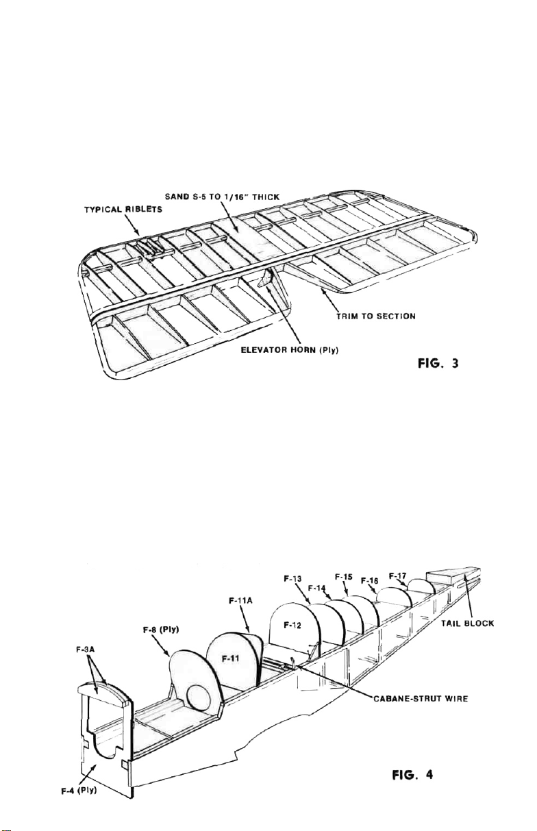
6. While this assembly is drying start on the stabilizer See Figure 3. Pin down
the 1/4" x 1/2" stab trailing edge (T E) to the plan Cut a piece of 1/4" sq to length
for the spar and thread ribs S-1, S-2 and S-3 onto the spar in correct order Do not
glue the joints yet. Glue and pin the ribs to the T E Note that the center two ribs
must be shimmed up 1/16" to bring the ribs centered on the TE
Laminate the two S-4 parts that make each tip Cut leading-edge (LE) to length
from 1/4" sq and glue to all ribs, with 1/8" shim under it Now glue all rib-to-spar
joints, and glue tips S-4 in place Sheet over center two ribs with piece S-5. Set
aside to dry
7 Remove fuselage assembly from board and turn right-side up At this time
you can put aside the fuselage plan-view as no more fuselage construction will be
done on the board Sand fuselage, trimming bottom longeron at F-l. See Figure 4.
Glue two F-3A pieces together and glue both to F-4. Glue F-ll to F-11A and
F-14 to F-14A. Lay these items aside to dry.
3
Page 5
File notches into the rear cabane-strut wire and attach to the hardwood blocks in
the crutch, using metal clips and woodscrews provided. Glue the shaped tail block
in position on the fuselage, also formers F-17, F-16, F-15, F-14 and 14A, F-13,
F-ll and 11A, F-8 and F-4. Formers 8, 11 and 13 must be glued at correct angles
(see side view). Take care here, as the fit of the cut panels F-23 to F-27 depends
on the accuracy of the angles on the formers.
8. Remove stabilizer from plan. Turn upside down and glue second S-5 in place.
Pin down 1/4" x 1/2" elevator L. E. Glue laminated E-2's together for tips. Pin
1/8" x 3/8"
and E-2 tips in place, also center ribs from
T.E.'s in position, shim underneath
1/4"
at rear edge. Glue all E-l ribs
1/4" x 1/2"
cut to length.
9. Sand the stabilizer smooth, rounding off the L. E. and tips. The small riblets
are simply cut from 1/16"x 1/8" and glued in place, then sanded to conform to
section when dry. These riblets are marked "optional" on the plan, since they could
be omitted without affecting the strength of the stab. However, for the sake of the
scale appearance it is worth taking the small extra time to incorporate them.
10.
When elevators have dried, remove from plan and sand smooth like the
stab. Glue in 1/16" ply elevator horn E-3. The stab and elevator can now be
hinged together using the material provided cut to length — see plan for positions.
Glue a small piece of 1/16" scrap sheet alongside the elevator horn to support the
covering. The stab is now finished.
PLY DIHEDRAL-BRACE
FIG.
5
11.
Make up the wing spars (see Figure 5) as follows: Take the 1/4" x 3/8" and
1/4" x 1/4"
basswood spars and cut two 8" lengths of each size. Glue these in the
BASSWOOD WING SPARS*
center of ply parts D-1 and D-2. Then glue long spars to each side at the same
angle as the ply parts, over the plan sheet #1. Construct four such spars: two from
1/4" x 3/8" and two from
1/4" x 1/4"
. It will help to pin these to the board right next
to each other while they dry, so as to have identical angles on all sets.
12.
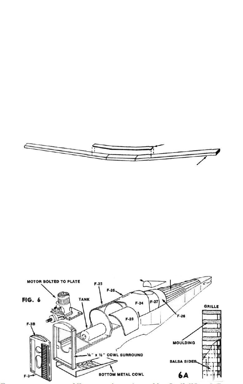
Glue ply F-7 between fuselage sides, lower front. The two holes are for
excess engine oil to drain away from the engine bay, and should be positioned just
ahead of former F-5. Glue the 1/4" x 1/2" strip parts on the front of F-4 and complete
the noseblock by glueing F-3 in place. Figure 6 shows these details. The radiator
grille is made from the mouldings supplied. Join two grille pieces and trim
long. Glue
4-3/4"
long pieces of
1/16" x 3/16"
on
each side
to
complete
the
to
4-3/4"
"box."
Make sure that all of the cross-bars are glued to these sides; and that the sides are
level with the front (open) side of the moulding. Later, when the glue dries, the
web holding all the cross-bars at the rear is sanded off, making an open grille very
easily and accurately. See Figure 6A. Repeat the whole process for the other grille
and cement the finished grilles over the large rectangular holes in F-3. Glue F-3B
in place. (Discard second F-3B in other Sheet 2).
HEADREST STRINGERS
Page 6

13.
Cut proper size hole in
1/4"
phenolic engine plate for the engine you are
going to use. Drill holes to suit and mount the engine. Fit the plate up to the
fuselage (remove the needle valve temporarily if necessary) and when you have
it fitting snugly down on the mounts, drill through plate and mounts simultaneously
to insure accuracy for the mounting screws. Screw plate in place using the
3/4"
woodscrews provided. Slide fuel tank in position and connect to engine with fuel
tubing.
14.
It is a good plan at this time to install the R/C equipment and the pushrod
to the throttle. Due to the enormous variations in available equipment it is not
possible to give precise diagrams for every R/C equipment installation: however,
the motor-control servo should be fitted between F-8 and F-ll. In the original prototype models, a Kraft proportional KP-4B outfit was used, and it was found very
convenient to mount the three KPS-10 servos for engine, elevator and rudder sideby-side on two
1/8" x 3/8"
basswood cross-spacers, so that all 3 servos were between
F-8 and F-ll. In this case the radio receiver was glued to the rear face of F-11A
via a small foam rubber pad.
The battery will fit in the space between F-5 and F-8. While it is true than an installation where the servos are ahead of the receiver is uncommon, this was one of
the cases where it was warranted. So plan your own equipment installation at this
stage. If you are a beginner at this, get the help of an experienced R/C builder!
We cannot put too much emphasis on this point. It is probably true to say that a
very high percentage of equipment malfunctions can be directly attributed to sloppy
or defective installation. Remember a long life for your model (and the safety of
spectators) depends vitally on good equipment installation.
15. After connecting the throttle to the motor-control servo, check for easy
frictionless movement over the whole range of throttle travel. When satisfied, remove the engine, tank and servos before continuing with building, so as not to get
any balsa dust, etc. in delicate equipment.
16.
READ THIS COMPLETE INSTRUCTION BEFORE STARTING.
The sheet panels F-23, 24, 25, 26 and 27 can now be glued in place. This may
appear at first to be a very difficult job to do without breaking the pieces. In truth,
it is very easy as long as the correct method is followed closely. We will explain
using one example piece, and the rest of the panels all follow the same general
idea. This is how to proceed: —
Take one F-23 piece and glue the lower edge to the right fuselage side (use regular
balsa cement). Let this joint dry thoroughly! If you try to continue too soon, the
joint will come apart and you'll be back at the start, and have to re-glue and wait
again. When dry, thoroughly dampen the outside of F-23, being careful not to wet
the glue joint just made. You can wet the wood with a cloth and water. After
a few moments, try pulling the sheet around the formers that it will be glued to.
You will find that it will bend to the required curve very easily. Spread glue (this
time use Titebond or white glue—not balsa cement) on the edges of F-8 and F-ll,
and pin the wrapped sheet firmly to the formers to set. Masking tape also can be
used to get firm contact.
The other panels are done in the same way. Glue F-26 in place before F-27. Wet
and attach one panel at a time. Start at the front again on the left-hand side. Notice
the panels are of slightly over-width as cut—this is to allow final trimming of the
left-hand pieces to exactly fit the right-hand ones already in position.
About the only panel that may give a little trouble is F-24 on the left side. (This
is why we had you do the right panels first—to get experience!) This is because
of the tight radius at the front over F-11A; so do not be concerned if a small split
develops here. After the panel has dried you can run some glue in the split or fill
with vinyl-spackle (purchase this at a hardware store). Notice also, that a small
clearance-cutaway must be made in F-25 and F-24 for the rear-strut wire. Any
oversize of these holes can be filled later with vinyl-spackle.
17.
From the 3/16" sq. supplied, cut seven pieces about 11-1/2" long and eight
pieces about 6" long. These will be the rear stringers. Trim one of the long pieces
to exactly fit from F-14A to the tail block and glue it into the notches in the center
5
Page 7

of formers F-14A • F-17. All stringers are to be glued in "diamond-fashion "
This was done to get sharp impressions on the covering, like the real S. E 5A
had, and yet have stringers big enough not to warp after covering Glue in the rest
of the stringers, observing that they are alternately long and short (see Figure 6).
When dry, cut back short stringers level with rear of F-16 Carve and sand tail block
to conform to fuselage shape
Shape the headrest block provided to section, and tack-glue in position so it won't
get lost.
18.
Glue R-l and R.2 together, also R-4 and R-5. Glue F-10 (ply) on front of F-8,
screw nylon brackets for upper cowl fastening onto F-10 and F-4: see fuselage side
view for positions
19.
Screw upper and lower metal cowls onto fuselage Shape and sand nose
block to correct contours and add dummy radiator-cap (made from scrap) Drill
upper cowl tor needle valve in required position by temporarily installing engine.
While upper cowl is removed from fuselage, shape cylinder fairings from blocks
provided, screw to upper cowl and finish making exhaust pipes from hardwood
dowels provided Figure 7 shows final appearance
20.
Cut a suitable hole in upper fuselage decking and tack-glue Vickers gun in
position, then cut out stiff card gun-fairing to template on plan and glue in position
Build
up windscreen,
lightly
tack-glue
on fuselage Sand fin and
rudder
parts.
Hinge together with material provided.
21. The whole stabilizer assembly, and the underfin (R-4 and R-5) may now be
glued permanently to the fuselage Take care while installing these parts to get
them properly aligned Lightly tack-glue the fin in position on the fuselage. Glue
rudder horn to rudder
22 Screw rudder and elevator servos in place Make pushrods to rudder and
elevator and check radio for smooth and free action of control surfaces. Bear in
mind here, that the type of pushrods required will depend upon how much interior
cockpit detail you intend to incorporate If you want, as we did, a completely
furnished cockpit with instrument board, pilot, seat and all the rest of the details,
it obviously will not do to have two big pushrods running through the center of
the cockpit In the prototype models we used short lengths of nylon tubing with
metal wire cable inside, from the servo back as far as F-14. From here back the
pushrods became 3/8 sq in the normal way The nylon tubing section was fastened
to the cockpit sides where it is hardly noticeable
If it is not intended to incorporate a full cockpit layout, normal 1/8 sq pushrods
all the way from the servos to the tail end will be all that is needed.
6
Page 8

Specific details cannot be given for these pushrods, because as with the radio and
engine, etc., requirements and equipment will differ from one builder to another.
Whichever layout is chosen it will be found that there is ample space inside the
model to carry out any desired positioning. However, we repeat to newcomers that
the advice of an experienced R/C modeler will be invaluable.
23.
Break up and discard false former F-12 from the fuselage. Smear a coat
of glue over the planking joint so exposed. Do not attempt to install cabane struts
at this time. For this job we will need the wings, so let's start those.
24. Refer to Figure 8 which shows the first section of the wing to be made—
the lower right-hand panel. Take one of the prejoined 1/4" x 1/4" basswood wing spars
and trim to exact length over the plan. Note that this is the longer rear spar. Slide
one W-3, one W-4 and six W-5 wing ribs in this order loosely onto the spar, pushing them toward the center of the spar temporarily. The dihedral brace on the
spar
faces
forward.
Cut
two
pieces
8-7/8" long
from
the1/8"x1/4"
balsa
strip
provided,
and glue these on top and underneath this rear spar at its outer end.
3/8" x 1/4" SPAR CAPPING
25. Take one of the pre-joined 3/8" deep basswood spars and cut to exact
length over the plan. This is the shorter forward spar. Spread out the ribs on the
rear spar and feed the forward spar through them from the root end, making sure
dihedral brace faces rear. Slide three W-6 and one W-7 ribs onto the forward spar
in correct order. Slide all ribs back and forth along both spars until they are all
in approximately the correct positions.
26.
Place scraps of 3/16" sheet or square balsa shims over the spar positions
on the plan, except at the outer end of the rear spar, where the shims should only
be 1/16" thick. Lay down the wing framework on the plan, with the spars held up
by the shims. As it is not practical to pin through the hardwood spars, hold the
assembly down with a few small weights, making sure it cannot move.
27.
Shuffle ribs to exact position over the plan (tweezers are handy for this job)
and lightly spot-glue each rib-to-spar joint. This will hold these joints while the
structure is completed; later on all these joints should be carefully and completely
glued when the wing is lifted off the plan and access is available all around each
joint.
28. Cut a piece of pre-formed L.E. section to correct length and glue in place,
shimming it up to the steps in the ribs with scrap 1/16" balsa. Pin and glue the preformed T.E. to the ribs, shimming up 1/16".
29. Glue two W-11 pieces together for wing tip. While these dry, slip W-8
riblets into place and glue. Trim front of outermost W-6 and glue laminated tip
W-11 in place and complete the tip with short length of 1/4" sq. to rear spar. Glue
in 1/16" x 1/4" stiffener against outermost W-5 rib, then riblets W-9 and W-10. Glue
W-17 in place.
30.
Glue in W-12R (ply) bellcrank bearer, noting that it lays at an angle. See
full-size drawing of wing section at this point on the Plan Sheet.
7
Page 9

31.
Remove wing from plan Slide four W-14 ribs over projecting ends of wing,
spars, getting them in approximately correct position in the wing center panel As
with the panel just made, weight down the spars with 3/16" shim under them
Slide ribs to exact position and glue See Figure 9 and 10. Glue in W-13 and
1/2" x 3/4" x 4" bass block Glue on L. E, the balsa block T. E Pieces and cap spars
with 1/16" x 1/4" to support the center 1/16" sheeting, which is now glued in place.
Don't forget to bevel one edge where the sheet sticks to the L E
32. Tilt the whole wing so the projecting spar-ends are now flat to the plan
and construct the left hand panel in the same way as the right Remember that ribs
W-3, 4 and 5 must be threaded onto the spars before the 1/8"
x 1/4"
rear spar capping
is glued on
33
. At this point turn the wing upside down and attach the formed rear landing
gear wire strut onto the hardwood block in the center panel, using the metal clips
provided Make sure you stay clear of the hole positions in this lower block.
34.
Again, cap the spars with 1/8" x 1/4" and sheet the whole underside with 1/16"
balsa
35. Refer to Plan Sheet I and study the full-size view of the lower wing center
section Fasten formed front landing gear wire strut to F-9 with metal clips
Glue F-22's onto wing Glue two F-9A's together, and set aside to dry. Glue F-9 to
F-22's. Then sheet in lower edge with parts
36.
Bring up the lower wing to the fuselage Trim or adjust parts if necessary
F-19, F-20
and F-21.
Aim for a perfect fit When this is achieved, take off wing, check that the laminated
F-9A's fit well into the hole in F-8. Sand if necessary When satisfied, glue F-9A
on the front of F-9, immediately putting lower wing in position on fuselage so that
F-9A will be in exactly the right position When glueing F-9A on, do not use too
much glue, else some may ooze out of the side and glue up the whole assembly
when the wing is positioned
37. While these parts are drying, slip two solder-tabs on each front LG leg,
then solder the landing gear plates to the legs Use acid flux here, as a strong
joint is essential'
38.
After carefully marking the positions of the holes for the nylon wing mounting screws on the underside of the wing center panel, drill right through wing and
the block
Redrill
in
the fuselage at one
the holes
through
time
the
Use a
wing
No
29
with a No
(.136")
19
or No
drill
Remove
18
(.166"-.170")
the
wing
drill
to clear nylon screw Tap the No 29 holes in the fuselage block with a 8-32 tap
Trim away F-19 to allow the heads of the nylon screws to seat right down against
the wing block When the model is finished, these recessed screw heads will be
barely discernable, and will not spoil scale appearance
Try screwing the wing into place See that all fits are perfect, trimming away or
adding if necessary
39. Slide the tabs on the front LG leg to the top of the leg, then glue all balsa
pieces LG-1 to LG-6 to landing gear legs, clamp up securely and set aside to dry
thoroughly Give these parts at least two hours—overnight if possible, before sanding down
When the legs are sanded down, bind them with
the 1/2"
tape supplied, wrapping
the tape tightly in spiral formation Rub glue into the tape This tape will strengthen
the landing gear and add to the scale effect
8
Page 10

40.
All four ailerons are identical—except of course that two are left and two
are right. Laminate each tip from two W-12 pieces. Construct flat on plan as in
Figure 11. When dry, carve and sand L. E. and tips to correct section: see Figure 12.
41.
Hinge ailerons to bottom wing—see diagram on Plan Sheet 1. The hinges
should be held in place by toothpicks after drilling through wood and hinge material
together. Cut down the nylon aileron horns supplied to correct size indicated on
plan and glue between closely-spaced aileron ribs, using Titebond liberally to fill
holes in horn. Clamp and let dry.
42.
Install nylon aileron bellcranks on W-12 (ply) bellcrank bearers. Connect
bellcranks and horns with supplied connecting links. Use small scrap of 1/16" sheet
to support covering where link exits from wing under surface.
43.
Mount aileron servo in lower wing center section. It will be necessary to
make two right-angled brackets in most cases. For this purpose, two drilled metal
strips are provided which can be bent and re-drilled to suit the application. Connect servo and bellcranks with 1/16" music wire pushrods, making the holes through
the ribs in the positions required by the equipment involved. Try to keep the holes
small—3/32" dia. is about right. Try out the ailerons using the radio, and do not
be satisfied with less than perfectly free and smooth movement over the whole
range of travel.
44.
The top wing is made in three stages just as the lower wing, so detailed
instructions are not necessary. The only points of difference are in the slightly
altered rib-spacings, the lack of servo or bellcranks, and the center section which
is rather simpler.
When making the center-section, note that the 1/16" sheet covering extends from
leading edge to the rear spar on the upper surface.
45.
So far we have a complete fuselage and tail, with a lower wing which is
mounted in position and an upper wing not yet attached. The next job is to bring
these two items together to make a fairly complete S. E. 5A. This stage is a little
tricky, so work slowly and carefully. Study the drawing of the strut attachment
fittings on Plan Sheet 1. This nylon ball-and-socket joint is a new idea that we at
Top Flite have worked out to greatly simplify the traditionally difficult job of
rigging biplanes. This new system is far less demanding of super-accuracy than the
usual wire-bending methods. Also, assembly and dis-assembly is easier and quicker
and appearance much neater. (These fittings, incidentally, are available separately
packaged, and biplane builders will find them very useful—they will take up any
angle of strut attachment . . . sideways, backwards, forwards or combinations
of these. Ask your hobby dealer for Top Flite E-51 package).
46.
From the
a 3/16" dia. hole in 8 of these 11/16" from one end and centered in the
width. Glue these to the spars (on top of lower wing spars, and underneath upper
wing spars) so the drilled hole lines up with the first W-6 rib. Trim away ribs
and riblets slightly where required. Refer to full-size plans to check location.
The 4 undrilled pieces are glued to the forward spars in line with the drilled strips
already attached. These 4 strips will provide a covering-support for your left palm
when snapping the struts in place.
Next cut 4 pieces of 1/8" x 3/8" basswood 7/8" long, drill 3/16" in the center
piece and glue to the bottom of the spars in the lower wing at the dihedral-break,
again trim away ribs to suit.
1/8" x 3/8"
basswood strips supplied, cut 12
9
pieces 1-7/8"
long.
of each
the
Drill
3/8"
Page 11

The nylon plates (sockets) are intended to be permanently screwed in place after
covering and clear doping and prior to coloring the model However, screw them
in place temporarily at this time to aid in the further construction of the model.
They should be removed later (see covering instructions)
47. Take one of the shaped hardwood wing-struts (1/4 x 3/4 streamline section)
and cut off a piece about 8" long This will be one of the forward cabane struts
(see Fuselage Side View Plan Sheet #2) Sand a slight angle at the top end of this
strut—see Figure 13. Drill a 7/64 dia hole into the strut from the end(Figure 14).
The hole should be about 1" deep and 1/4" from the L E of the strut Fill the hole
with Titebond or epoxy glue and push in the threaded shaft of the nylon ball strut
fitting (Figure 15).
This joint must be allowed to completely dry before anything more can be done
with the strut
BALL FITTINGs
FRONT VIEW
Fig.
Pig.
13
14
Fig.
15
48. Meanwhile, cut the other cabane struts and also the interplane struts from
the formings Always leave 1/4" or so of extra length, to allow for final tailoring
at the assembly stage One end of each strut can be angled and drilled, however,
and the ball sections glued in Note that the cabane struts are rectangular in side
view (as the struts are supplied) while the interplane struts have a curved taper at
each end Carve this shape into the interplane struts and sand rectangular edges
back to airfoil section
49. When the first strut (front LH cabane) is set, snap the nylon ball into
its mating socket, which is the nylon plate screwed under the forward spar of the
top left-hand wing at the dihedral joint
The diameter of the hole in the flat nylon piece has been designed to resist the
ball-end on the strut to a fair degree Therefore a firm push will be required Once
snapped in, however, the joint should be quite free to assume correct angle
50. With both left and right forward cabane struts snapped into place on the top
wing, cut out a hole in the fuselage sides immediately behind F-8; see Figure 16.
Enlarge until the bottom ends of both cabane struts can be fed into the slots Cut
two pieces
of
scrapwood,
one
2-1/2"
long, the
other
3-3/8"
long Pin these
to
the
T.
E.
and L E respectively for use as incidence and height gauges See Figure 17. When
the whole assembly is fitting well, check that the wing is properly squared-up to the
fuselage in plan view and front view (Sight by eye using the attached bottom wing
Fig.
16
HEIGHT-GUAGES - LONGEST AT L. E.
TRIM HOLE UNTIL STRUT CAN
SLIDE IN AT CORRECT ANGLE
10
FIG.
17
REAR CABANE-STRUT WIRE
Page 12

as a reference) When satisfied, run some Titebond into the holes at the strut-fuselage
joint When this glue has dried and the top wing will not move out of alignment
remove the bottom wing so that access can be had to the inside of the fuselage and
liberally glue the struts to F-8.
51. At this point in the construction, all the most difficult work is done; now
we re coming down the home stretch'
Snap the rear cabane struts into the top wing fittings Mark length and angle down
to the stub wire projecting from the fuselage Disengage strut A good way to
unsnap the ball is to insert the blade of a wide screwdriver in the gap between the
wing and the end of the hardwood strut Twist the screwdriver and the fittings will
disengage Cut and drill lower end to take wire Replace and remove struts, trim
ming
as
necessary
in struts with glue and slip into place on the wire snapping top fittings together
to hold alignment perfect while glue sets When dry, remove balsa height gauges
52. Fit the four interplane struts First cut the struts to exact length to fit
between the nylon plates Then cut off 3/16" of length drill struts and glue ball
fittings in place Constantly check that wings are parallel and at same incidence
(L E top wing to L E bottom wing distance should be same as T E top to T E
bottom)
53. Install all solder-tabs in position to be used later for wire rigging attachment
54. Solder the axle into the landing-gear plates. Trim the shaped hardwood
axle fairing to proper length and angle, and glue to the legs with the axle running
in the groove visible from the top
A completely rigid landing gear is, in our experience, by far the best for this type
of model The small amount of springing incorporated into the axles of the fullsize aircraft of the period, has proven of no value in cushioning landing shocks on
models, and in fact, causes ground looping problems on take-off
55. The scale propeller is supplied as a shaped blank ready
section Carving propellers is an acquired art If you doubt your ability to make
a good Job have an experienced modelling friend do it for you The many exterior
details may now be built
cockpit detail and so on
Smooth off rib edges, etc., and remove any bumps of glue that would spoil the
covering Job
Disassemble interplane struts and wings from model and remove nylon fittings
from wing panels Remove from the model all tack glued items such as fin and
rudder, guns, cowls, headrest, windscreen, etc. Remove engine, R/C equipment
and also the pushrods if possible
Completely disassemble the whole model as far as possible into its separate
elements After again making sure that all structure is smooth, we are ready to
cover the model
WARNING: Some of the heavier fabric covering materials, such as nylon,
heavy silks and blends of silk and nylon, are not suitable for models of this type
They have too much shrinking power and will warp the structure Use only regular
lightweight or Japanese silk to cover this model!
Start by giving all wood which will come into contact with the silk two coats
of clear dope Use dope liberally, allowing each coat to dry
Sand doped areas lightly to remove the fuzz raised by the dope
Cut panels of silk to oversize and lay on model Paint around outlines with
clear dope The dope will penetrate the silk and form a bond with the dope pre
viously applied Stretch out all wrinkles as you go
Do
not be concerned if the covering is a little
drumtight
or
folds
When the dope has dried, lightly spray the silk with water An airbrush or
perfume spray will be ideal When the silk dries it should have shrunk quite tight
until
the
fit
is
right
and installed temporarily, such as gun rail and gun,
at this time—the important t
Finally,
COVERING
hing
with
strut off the fuselage,
is that there should be no wrinkles
11
loose. It does not have to be
fill
holes
to be carved to
Page 13

If there are places where it has not tightened properly or there are wrinkles or
folds remove that panel of silk and do it over. Never expect the shrinking action
of the clear dope that is applied next to pull out a bad covering job. It never does —
dope will not shrink out wrinkles that water cannot remove. Clear shrinking dope
can only make an excellent job of an already good one.
When you have a good covering job, give the model 3 or 4 coats of clear
dope. Thin the dope out. Two thin coats are better than one thick syrupy one.
If
you have a spray you will get a better job.
One piece of advice regarding clear-doping is worth passing on: When doping
the wings, give a coat to the top of one panel and immediately coat the bottom
of that panel. In this way the wing will be subjected to even stresses all around
and warping will be minimized. Do one panel at a time. The same goes for the
stabilizer, elevators and ailerons.
Inspect the wings, ailerons, and stabilizer for warps. Remove any that are
present by holding near (not too near!) heat and twisting gently in the opposite
direction. Take care here, as warps will have a very bad influence on the flying
characteristics.
When the clear doping is completed, proceed to the color. Color dope should
be sprayed if at all possible. The nylon strut fittings can be replaced prior to color
doping. Give at least 3 coats of all colors.
Since most, if not all, S. E. 5A's were doped with matte comouflage dopes,
we now have to kill the unwanted high gloss that our regular model dopes give. The
best way to do this is to spray a coat of clear eggshell lacquer over the colors.
Be sure that the lacquer you use is fuelproof—polyurethane varnish is very suitable
and can be obtained from hardware stores or paint stores. Normally such varnishes
will not be found in model shops.
Finally, add the decals in positions indicated on the plan. Many S. E. 5A's
had the words "LIFT HERE" along the bottom longeron together with a small
white arrow. The particular S. E. 5A we chose, Mike Mannock's D'278 did not
have these markings, but if you choose to paint your model with a different serial,
you can use the words LIFT HERE and the small arrows which are provided on
the decal sheet.
FINAL DETAILS
Like all full-size aircraft, the S. E. 5A was loaded with small details, such
as radiator cap, pilot tube, sumps, and dozens more. Probably, most "Sunday
Fliers" will not want to incorporate these. But for the contest flier, or modeler
who is making this model for static display purposes, and wants to incorporate
these details, cockpit furnishings, etc., we have given drawings on the plan to enable
these details to be made.
If you intend to go this route, we recommend the book, "S. E. 5A" by
Charles L. Bourget available from World War I Aero Publishers, Box 142, West
Roxbury, Massachusetts 02132, at $1.95. The drawings in this book are the ones
we used in scaling the model, because we considered them the most accurate obtainable for this aircraft. We have reproduced these drawings on our plan, enlarged
to 1/2" = 1' scale as an aid to contest fliers in preparing their "Proof of Scale"
documents.
The "Profile" Publication of the S. E. 5A is also recommended, and will be
especially useful, along with our box label, in giving guidance to correct coloring of
the model. The "Profile" (No. #1) is obtainable at most hobby shops and costs 50c.
RIGGING
Due to the scale wing section being so thin, the wings are very flexible. In
our considered opinion the wings would not be strong enough for flying if left
unbraced. When correctly rigged, however, the strength of the "box-kite" wing
configuration is enormous, and will withstand any amount of severe maneuvering
in flight with strength to spare. To have made the wings sufficiently strong as
cantilever structures in the design stage would have been possible, but at the
expense of considerable damage to scale effect, by way of a wing section of twice
scale thickness and areas of sheeting. We chose to make the model true scale and
12
Page 14

make the rigging wires, which have to be added in any event, perform a real and
important function.
After all the dope on the model is completely dry, screw the lower wing in
place on the fus>elage. Snap the upper wing onto the cabane struts. Snap the four
interplane struts into the wings. The rigging wires are made from the 020" piano
wire supplied, and are called "flying" and "landing" wires — the "flying" wires
are the ones tensioned in flight, that is, the ones running from the fuselage up to
the upper wing the "landing" wires are the ones tensioned in a landing, that is,
the wires running from the top of the cabane struts down to the lower wing
As with the strut fastening method, we have given a good deal of attention
to figuring a simple and fast way to install the rigging wires. We did not want
to use turnbuckles. (the traditional method of getting the correct wire length)
because they are tiresome and must be reset every time the model is disassembled
for transportation
FIRST Z-BEND
FIG.
18
IMAGINARY "TABLE" AND "BLOCKS" DRAWN ONLY TO SHOW BEND DIRECTIONS
The method we have devised will take a little patience to bend the wires,
but once done, the wire length is set permanently, and the wires can all be removed and replaced in seconds. Follow this method:
a Start by making the longest wires first. This way, if you accidentally
bend one too short the same piece can be used for a shorter wire later
on, saving waste. Work through to the shortest wires, doing these last.
b Leaving the wire the full 30" length, make a small normal Z-bend at
one end. See Figure 18.
c. Hook this Z-bend into the solder tab at the top of the front interplane
strut on the left side
d. Holding the wire in slight tension, make a mark on the wire (use a
felt-tip pen) where the wire passes the solder-tab at the top of the front
L.
G.
leg.
e Unhook the Z-bend. Bend the wire at the pen mark 90°. Now make
another 90° bend about 1/8" further along perpendicular to the long
straight section. Again, see Figure 18.
f. Cut off the wire about 1/8" along the new direction. The wire is now
made. Let's see if it fits o.k.
g See Figure 19. Hook the original Z-bend back into the tab it came
from. Now, by grasping the wire at the lower end with pliers and
twisting it, hook the other end into the second solder-tab. We are using
the torque in the wire to keep the bottom bend in the tab, and unless
the rigging wire is twisted the bottom bend cannot disengage. This
cannot happen in flight: however, removal is simply performed by
grasping the wire near the bottom with pliers and twisting until the
wire disengages.
13
Page 15

HOOK UPPER Z-BEND IN FIRST.
FIG.
TO DISASSEMBLE REVERSE INSTRUCTIONS
19
h Test the wire for tension When plucked the wire should feel taut
If the wire is slack this is no good and a new wire must be made—note
how much shorter it has to be If, on the other hand, the wire is
bent too short it cannot be engaged at all since it will not reach the
second solder tab
i All of this might seem terribly difficult to get "just right" but we can
assure you that after making one or two mistakes, you will be making
almost all of the rest of the rigging wires "dead on" first time! Your
judgment quickly attunes to the requirements of the wire
With all the rigging wires in place on the model, a method of identifying
each wire must be seen to A good way is to color code each wire with a small
Jab of dope at one end Keep a list of the wires and the color-coding in your
flying field kit
AILERON CONNECTORS
These units are very simple Cut the tiny horns out of scrap 1/16" ply after
drilling the 1/16" dia hole Make a small slit in the covering and glue the horns
in position—top of lower ailerons and bottom of upper ailerons
With the wings completely wire rigged, set the lower ailerons dead neutral,
using the links to adjust as necessary
Bend one end of the 9" long 1/16 wire supplied 1/4" from the end and a
90° angle Fasten this end to the lower aileron using a nylon button retainer to
keep it in place Hang a connecting link in the upper horn, cut the wires level
with each other and join with a short tube soldered in place See Figure 20.
Adjust the connecting link so the upper aileron is also at dead neutral
later,
when trimming
out
the model
in
flight,
each
aileron can thus
be
adjusted
individually for the best result
-NYLON BUTTON-RETAINER
FIG.
TUBE
ADJUSTING-LINK
20
14
Page 16

PRE-FLIGHT CHECK
This is probably the most important Job to do on any model Right here is
where the complete success of the maiden flight is organized A somewhat tiresome task to do properly, but hurry here can lead to an expensive crash Let's
break down the pre-flight check into three units.
1. Balance
2. Alignment
3 Equipment
First, balance. The model should balance level to the ground or slightly
NOSE DOWN when supported by its wingtips on the fingers or some blocks at the
point marked CG on the plan (sheet 2) This is exactly half-way between the
leading and trailing edge of the upper wing
Due to the naturally good layout of the S E 5A for modeling, it will
almost always balance properly However, if it becomes necessary to alter the
balance point, try to do so first by moving some fairly heavy item of equipment
(such as the battery) to a new location If this is not possible, weight must be
added to nose or tail
However, much is needed this must be put in the model While it is admittedly
a shame to add, say, half a pound of dead weight, it is the only answer Never
be trapped into thinking that the extra weight will do more harm than incorrect
CG location'
If your model is nose heavy (CG too far forward) the worst that can happen
is a slight sluggishness in control response This presents no problem and can be
rectified before the second flight. With tail-heaviness, however, there is frequently
NO second flight'
Second, alignment. This check consists of finding out if the incidences of
the wings and stab are correct Proceed as follows Stand the model on its wheels
on a level surface—a dining room table will do fine Now block under the tailskid
with books, etc until the measurement from the table up to the L E of the stab
is the same as up to the T E of the stab It is important, of course, to have
previously set the elevator at dead neutral Having got the stab accurately parallel
to the table, measure the incidence of the lower wing
To do this, measure up from the table to the middle of the L. E at the
dihedral break Make a note of the figure Now measure from the table to the
T E point, at the same dihedral break This second figure must be somewhere
in the range of The same as the first figure to 3/16" less than that figure. (That is,
between 0° and +1° incidence)
Finally, check the upper wing incidence This is very simple At the same
dihedral break as used before, measure the L E bottom to-L E top wing then
the T E bottom to T E top wing The figures should be the same It is allowable
to have slight positive incidence on the upper wing relative to the bottom one
That is, if the T E -to T E measures 1/8" or so less than the L. E.-to-L. E. figure,
do not be concerned
As long as care was taken during the construction it is doubtful that the
alignment will prove to be wrong beyond the tolerances allowed If, however,
such is the case, make the necessary alterations by regarding the lower wing as
correct and aligning the upper wing and the stabilizer to this Trimming the length
of the two forward or the two rearward cabane struts will decrease or increase
the incidence of the upper wing respectively (also trim the interplane struts to
match), the stabilizer can be brought into alignment with the lower wing by cutting
it free from the fuselage and re glueing it back after trimming-out the rear fuselage
sides to change the angle as required
Lastly, equipment. Switch on the radio and check carefully all control surfaces
for free movement Eliminate any over freeness that could cause rattles Check
motor control Do not be satisfied with less than full 100% perfection in this area'
To lose a good model from accidental causes is bad, to lose one because of hurried
checking of RC equipment is unexcusable because it could have been avoided.
15
Page 17

PRE-FLIGHT RUN-UP
Before actually committing the model to the air, it is a very wise precaution
to perform a simple "flight-conditions" check by running-up the engine and check-
ing the radio on the ground. On arrival at the field, proceed as follows:
a. CHECK OPERATING FREQUENCIES OF OTHER MODELERS
PRESENT!
b. Remove upper cowl. Fill fuel tank and start engine. Adjust to correct
high—RPM.
c. Set engine for idling—RPM. Stop engine. Re-start and stop several
times to be sure you can start the engine easily and quickly when it is
at idling—RPM setting
(This latter point is very important! While starting, under some cir-
cumstances, flooding for instance, an engine will occasionally spit
burning fuel onto the model and begin to set it afire. This is no problem
when the engine is uncowled because it is easy to just blow the fire out:
however, you cannot do this after the cowl is screwed on. When the
engine is started at idle setting this occurance is prevented by the
exhaust-baffle blocking the exhaust port. We draw this matter to your
attention because "forwarned is forearmed").
d. With engine running, switch on radio and hold model up by its upper-
wing center-section. Check all controls, including motor RPM.
When satisfied with results of the run-up test, we are ready for the allimportant moment!
FLYING THE S. E. 5A
For
the expert at flying radio-controlled models the S. E. 5A will present
few problems. About the only area in which care will be needed is in the take-off
run, where there sometimes is a tendency to ground-loop. We have discovered
that this happens mostly when a take-off is attempted with gradually increasing
power. The answer is to snap the throttle open from idle quite sharply, the
resultant sudden power burst will allow the model to take off straight and well.
If possible, avoid rudder corrections during the take-off run as the model is
abnormally sensitive to rudder and it is easy to apply too much correction.
Ground-handling characteristics on slow engine speed, however, are very
good. "Slipping" the throttle for ground steering looks and sounds good on a
model of this type.
In common with other biplanes, with their high drag of struts, wires, etc.,
the glide of the S. E. 5A is flat but fairly steep. The airplane does not have the
aerodynamic "cleanness" to make long low approaches with a dead engine. Therefore
always try to land before the fuel is all used, so that the engine can be used for
making a good approach-path.
To the newcomer, or modelers of little flying experience, who need to know
the best method of handling the first flight of the model, our advice has to be
"Don't!" Give the model to an experienced clubmate or friend to make that allimportant first trimming-flight. Once trimmed, the model will be no more difficult
to fly than a regular Taurus-type model. Neither is it any easier. Flying experience
cannot be taught in written instructions such as these—it must be acquired over
a period of time. So proceed with caution—and get all the help you can during the
early stages of learning to fly.
In addition to the actual construction sequence of this model, we hope that
we have passed on to you some helpful ideas gathered from our own experience.
If you follow along these lines we know that building and flying your S. E. 5A
will be a rewarding experience.
Best of Luck!
TOP FLITE MODELS
16
Page 18

 Loading...