

Page 1
RC-38 PHASOAR 035 INSTRUCTION MANUAL
I. INTRODUCTION
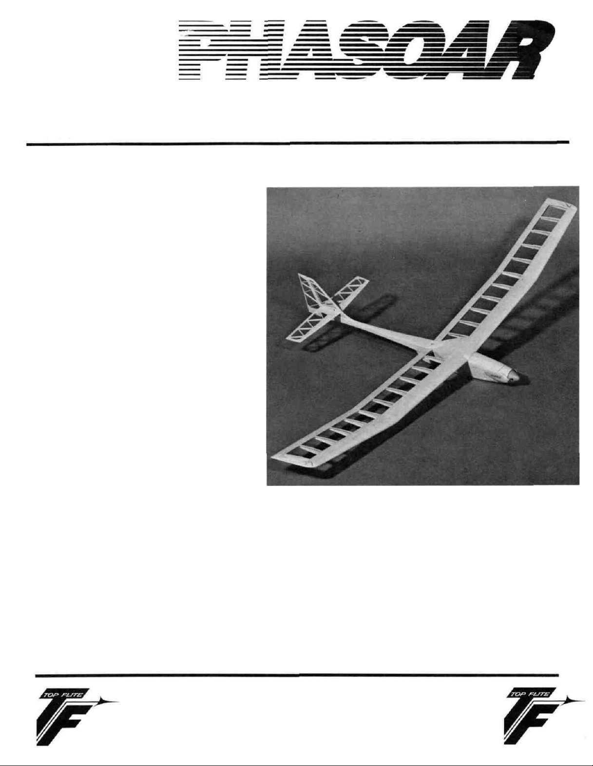
The PHASOAR 035 from Top Flite Models,
Inc., utilizes its unique looks and design
to deliver electric-powered performance at
the flying field! All of the latest
technology has been employed in designing
this model, starting with the silent, but
powerful, ASTRO FLIGHT Cobalt 035 Electric
Motor. This motor, with a GRAUPNER 7x3
folding propeller unit and a SR 1000 or
"Magnum" 1250 mAh battery pack (6-cell),
has rocketed our prototype PHASOARS to 700
feet in 55 seconds! This was done up to
five times on a single charge!
Aerodynamically, your PHASOAR has a light,
straight-forward and strong airframe.
There's no need to disassemble the model to
get at the batteries because its singlescrew release allows quick access to the
battery pack. This allows you to charge
batteries while still in the pod or remove
them for charging while a second pack is
being used. The full-flying stabilator
allows the model to be quickly and
dynamically trimmed for power-on/power-off
flight. The PHASOAR"s airfoil allows
flying in wind conditions that would ground
most of the flat-bottom types and, yet,
provides a great thermal-hunting glide.
The generous rudder area and the
appropriate polyhedral of the wing panels
allow quick detection of the core of the
smallest thermals for long unpowered
flights.
Finally, the PHASOAR is perfectly sized to let you
take it most anywhere and enjoy true, highperformance electric flight.
IMPORTANT NOTE:
If you are a beginner to the sport of R/C flying,
we would urge you to seek and use experienced
assistance in constructing and- flying this
airplane. All model airplane hobbyists should
remember that:
Flying this or an other radio-controlled model
aircraft is a PRIVILEGE and not a RIGHT and this
privilege begins with the utmost safety
considerations to others and yourself as well. An
TOP FLITE MODELS INC.
2635 S. WABASH AVENUE • CHICAGO, ILLINOIS 60616
R/C model airplane in inexperienced hands has the
potential of doing serious personal or property
damage. These safety considerations start at the
building board by following instructions, seeking
competent help when you are confused and avoiding
short-cuts. These considerations have to be
carried over to the flying field where safety must
come first.
done so, to:
1. Send for and obtain your Academy of Model
We
urge you, if you have not already
Aeronautics (AMA) membership which provides
insurance for your R/C activities'-DO NOT
RELY ON HOMEOUNERS INSURANCE.
Page 2
2. Join an AMA-sanctioned R/C flying club in
your area where you can obtain experienced
guidance and instruction in trimming and
learning how to fly this model.
Many local hobby shops have the required AMA forms
or can advise how/where they can be obtained.
WARNING!!!
A radio controlled model is NOT a "toy." Care and
caution must be taken in properly building the
model, as well as in the installation and use of
the radio control device. It is important to
follow all directions as to the construction of
this kit as well as installation and use of the
engine and radio gear. The advice and assistance
of a well-experienced builder and pilot is highly
recommended. Don't take chances! Improper
building, operation, or flying of this model could
result in serious property damage and/or in serious
bodily injury to yourself or others.
II. PRE-CONSTRUCTION NOTES
The PHASOAR, like other Top Flite kits, employs the
use of die-cut wood to ease the task of
construction, part fit and identification. Die-cut
parts may be removed from their sheets by first
lightly sanding the back of each sheet before
carefully removing each part. Use a light garnet
paper for the sanding and keep a sharp hobby knife
with a #11 blade handy for assistance in removing
any parts that might not have been completely cutthrough by the dies. Parts which oppose one
another must be precisely uniform (such a ribs,
etc.) and should be carefully "matched" after their
removal from the part sheets. Matching is the
process of holding the pieces together with either
pins or tape, or by spot gluing and lightly sanding
the edges of the parts until they are identical. A
sanding block with light garnet paper is most
useful for this.
* Straight-edge, preferably metal, at least 36"
long
* 90" triangle
* Soldering iron, flux (such as HARRIS' Stay-
Clean) and solder (silver)
* Carbide cut-off wheel for wire cutting
* Small power jig-saw, such as a Moto-Saw
* Razor plane
* Tapes, such as masking and cellophane
Our PHASOARS were constructed using a variety of
common hobby adhesives including 5-minute epoxy and
cyanoacrylate (CA). Type of glue used may vary
according to individual preference. However,
during the construction there will be call outs for
certain types of adhesives, and we urge you not to
substitute since doing so could possibly cause
structural problems.
Your flat building surface should be at least large
enough to accommodate the wing, yet be able to
accept pins easily. A product such as Celotex
fiber board works well. Another good surface is a
2' x 4' fiber board ceiling tile.
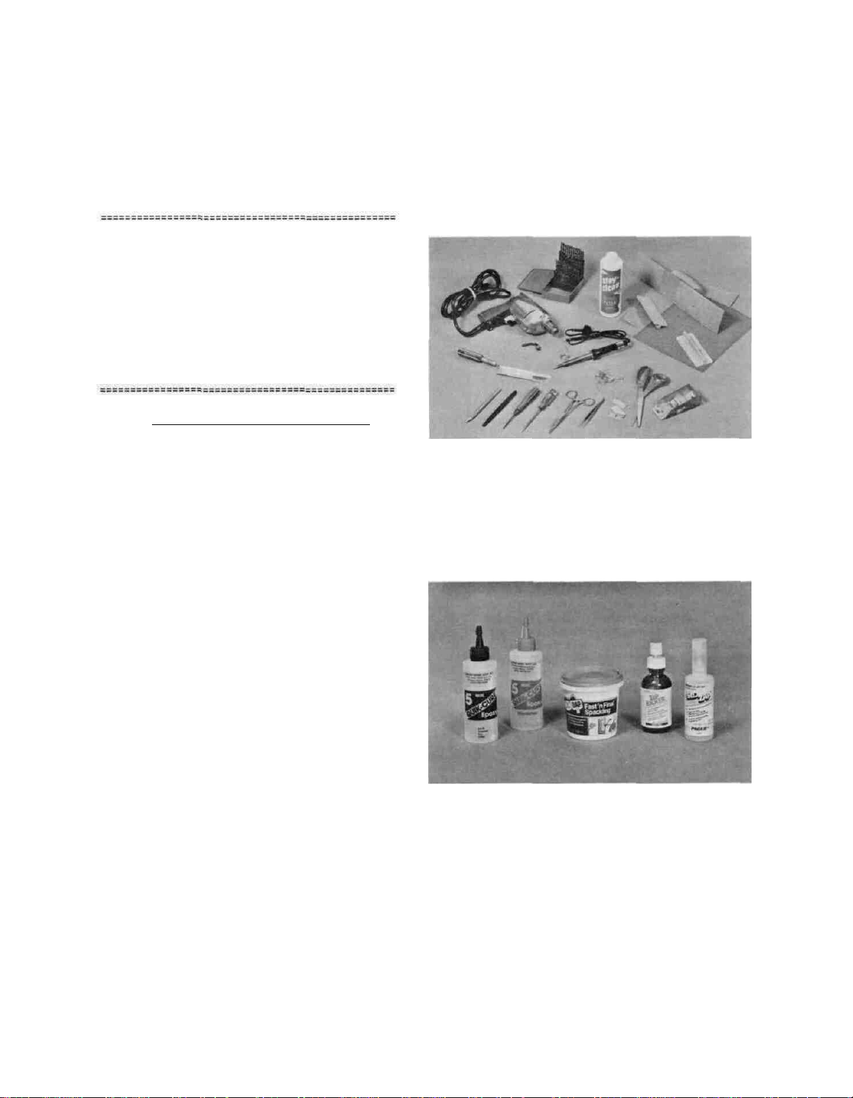
As with most R/C kits that are constructed from
wood, a selection of tools and accessories greatly
help do the job correctly:
Hobby knife with sharp #11 blades
Single-edge razor blades
T-pins
Sanding blocks in assorted sizes
Sandpaper in various grits
Hand-held hobby saw, such as an X-Acto
* Dremel tool or power drill and assorted drill
bits
Left to right:
*Good quality 2-part 5-minute epoxy
*Good quality, sandable filler
*CA accelerator for CA glue
*Good quality, slow-set CA glue
Lastly, the sequence in which the PHASOAR is
assembled has proven to be the most straightforward and provides finished components in the
order in which you will need them to progress to
2
Page 3
the next assembly phase. Maintain the building
order presented here to avoid mistakes.
Spread the plans out on your work surface, cover
them with a clear plastic material, such as the
backing from a roll of MonoKote or plastic wrap,
and commence construction.
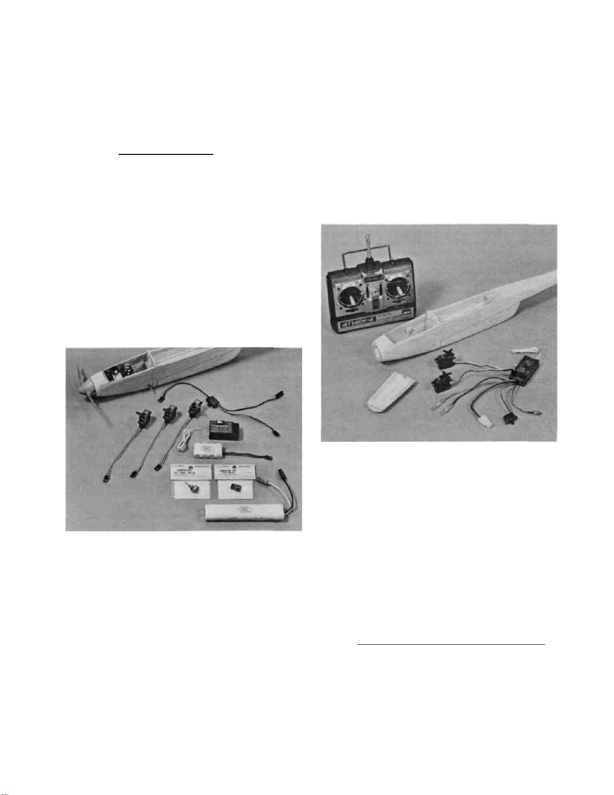
III. RADIO SYSTEMS
Our prototype PHASOARS have been tested and flown
using two radio types from different manufacturers.
The first of these radio systems is the one
depicted on the plans. The system consists of a
standard-sized 6-channel receiver (AIRTRONICS
#92262), three micro-servos (AIRTRONICS #94501) and
a standard-sized, internally-mounted switch harness
(AIRTRONICS
system by a 4-cell SR 300 mAh battery pack, fitted
with an AIRTRONICS connector. The servos have been
fitted with the 4-arm servo output arms, with three
of these arms cut-off and the remaining arm trimmed
as shown on the plans.
These three servos drive the rudder, stabilator and
the ON/OFF micro motor switch.
#97001).
Power
is
supplied to
this
fully-proportional, motor controller. Secondly,
the receiver and servos are powered by the motor
battery pack, thus, eliminating the need for a
separate, on-board battery supply for these
components! This means that there is no need for
a micro-switch, the wood mounts, the hardware to
mount these parts and no need for the arming switch
because the FUTABA system has all of these
components built-in. This system is available with
FUTABA's #S-133 servo included. The S-133 servo
has almost the same dimensions as the AIRTRONICS
#501 servo, thus no adjustment to the plans in the
servo area is required. Lastly, this system
includes FUTABA's Attack-4 transmitter which is
equipped with servo-reversing.
The radio system just described is very acceptable
in terms of weight and reliability!
The transmitters we've used in conjunction with the
above system were the AIRTRONICS Championship
Series 6-channel and the AIRTRONICS SR Series 4channel. Both of these worked well. whatever
system you choose, we suggest that the minimum
requirement is servo-reversing ability.
The second radio system that we've used is made by
FUTABA. This radio system has sophisticated
features that work well in the PHASOAR. First,
when using this system, your servo count goes from
three to two. because the receiver also houses a
FUTABA's System #4NBL 133MN 72 designates the radio
which
will
mentioned.
provide
For comparison, the airborne weight of the FUTABA
system is 3.25 ounces. The AIRTRONICS system
described earlier, with the micro-switch, mounts,
hardware and arming switch weighs or 5.93 ounces.
The difference amounts to 2.68 ounces, or nearly a
10% loss of weight for the model which uses the
FUTABA system!
There are other systems that would also work in the
PHASOAR.
Have whichever radio system selected available for
sizing and fitting purposes during construction.
all
of the
components
IV. MOTOR AND PROPELLER CHOICES
The PHASOAR has been designed and engineered to be
powered by the ASTRO FLIGHT 035 Cobalt motor, using
direct drive. This motor is relatively small,
light-weight (about 130 grams), very powerful for
3
just
Page 4
its size and quite easy to mount/install. It
swings a 7-3 or 7-4 propeller and accepts a wide
variety of battery packs.
The photograph shows the five (5) battery-pack
types and capacities that we've used to power the
PHASOAR.
There are other motors that will fit into the
PHASOAR's nose, e.g.. the KYOSHO LEMANS 360, the
MABUCHI RS-380SH, and the ASTRO FLIGHT 020 Cobalt,
etc. We must, however, forewarn that these motors
are not going to yield the kind of high-performance
climb-to-altitude that the PHASOAR has been
designed for. Decide now which motor you want to
use
because
during construction.
The propeller choice always tends to be a function
of experience in flying the model. Therefore,
propeller sizes and diameters can and should be
"played with" to determine which one works best.
Our first recommendation is to seriously consider
a folding propeller. Since the PHASOAR is. in nonpowered flight, a sailplane, it derives a certain
amount of efficiency by being quite aerodynamically
"clean." while fixed-blade propellers work well,
the folding units tested performed better after
cutting power.
you
will
be
fitting
it
to the fuselage
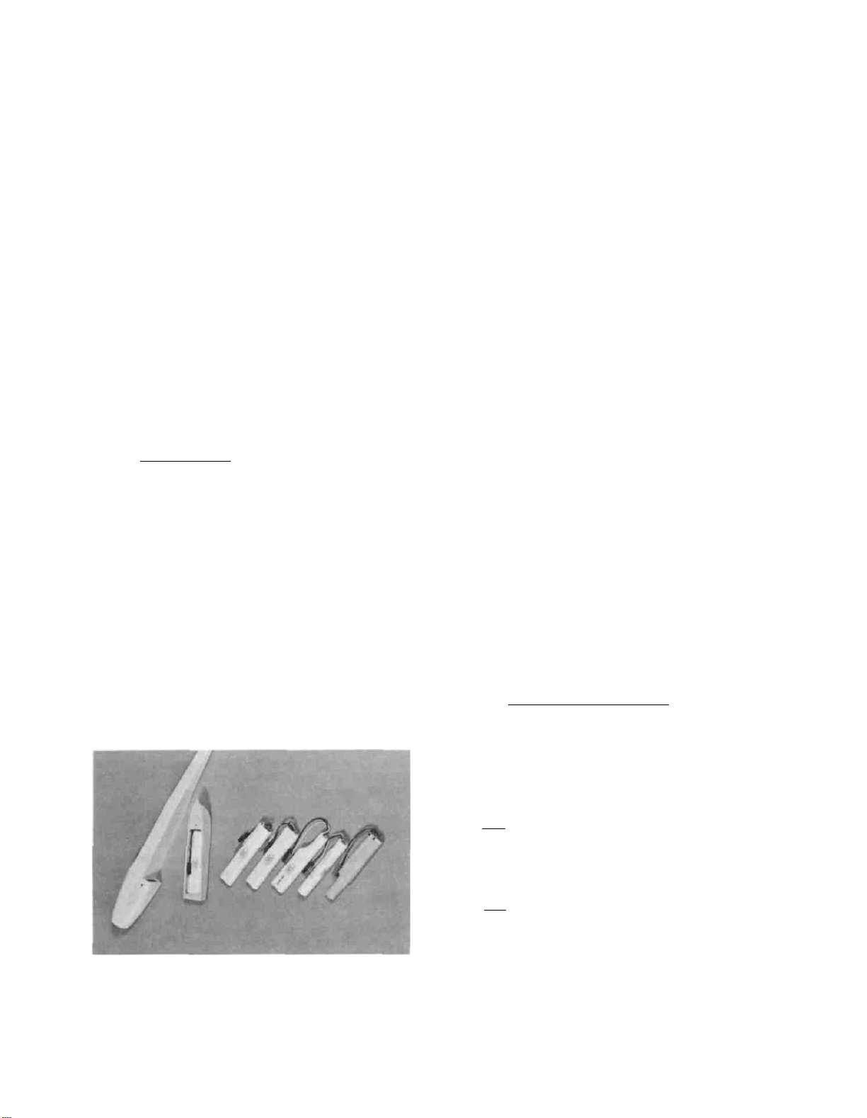
V. BATTERIES
Your PHASOAR's battery pod has been designed to
carry six (6) AA-sized batteries, or four, possibly
five (if configured appropriately), "Sub C" type
batteries. The capacities of these two battery
types can and do vary and it is important for you
to know at least some of the differences. It is
also important to know that the current drain, when
using the ASTRO FLIGHT 035 Cobalt motor. Is higher
than that of a ferrite-type "can motor." Because
of this, it is appropriate to provide your model
with the best possible set of batteries, both in
terms of capacity and certainly in terms of weight.
Why worry about weight? The single heaviest, FIXED
WEIGHT item that your PHASOAR must carry aloft is
the battery pack. This weight directly influences
the wing loading of the model which dictates how
the model behaves when the power is OFF.
First, on the left in the pod, is the SR 1250 mAh
"Magnum" 6-cell pack. Moving from left to right in
the row of five packs, is another SR 1250 "Magnum"
pack. The next pack shown is the SR 1000 pack,
then the SR 1000 pack in a 5-cell format. Next is
the 4-cell, Sub-C SR 1000 pack, and at the far
right is a 5-cell pack made-up from Sanyo 800
cells. The weights for these units (all with
connectors) are as follows:
These numbers are revealing, especially when tied
into the capacities (potential amount of power) of
each of the packs and their effects on the model's
wing loading. All five of these packs have been
used in testing the PHASOAR and all five have
worked well. The best all-around battery pack has
been the SR 1250 (mAh) 6-cell pack, since it
provides the amount of power that the 035 Cobalt
thrives on. At the same time, it has an acceptable
weight for thermal hunting with the PHASOAR's wing
area (335 sq. inches) and resultant wing loading
(with this pack in place) of 11 ounces/sq. ft.
using the AIRTRONICS equipment or 10 ounces/sq. ft.
when using the FUTABA system.
To get the most out of your PHASOAR, in terms of
flying time, consider obtaining three (3) battery
packs. In this way you can be flying almost
constantly because one pack will be in the model,
one pack will be cooling and the third will be on
charge. With only a single flight pack you could
conceivably have to wait 35 to 40 minutes between
flights.. Be sure to follow manufacturer's
recommendations for recharging the batteries.
SR 1250 6-cell "Magnum" pack. . 7.43 oz.
SR
1000
6-cell
pack
SR
1000
5-cell
SR 1000 4-cell Sub-C pack . . . 6.09 oz.
Sanyo
800
(mAh)
pack
5-cell
......
......
pack . .
7.60
oz.
6.43
oz.
6.52.oz.
VI. BATTERY CHARGERS
There are a great many chargers available for recharging Nickel-Cadmium batteries (Ni-Cads); too
many to test them all. We have had success with
the two we use and, therefore, recommend these to
you knowing that many others may work out just as
well.
For fast charging (15 to 20 minutes) the LEISURE
#107 AC/DC model works well and can be either used
on your auto's 12-volt battery or plugged into a
110 volt wall socket. Great for quick charges at
the flying field.
For slow charging ACE R/C's DUAL-METERED VARICHARGER (#34K32) is available in both kit form and
pre-assembled. It allows two battery packs to be
charged simultaneously. Super when you have the
time at home to top-off the charge in each pack.
4
Page 5

VII. WING CONSTRUCTION
Be sure and protect your plans by covering them
with backing from a roll of MonoKote or a material
such as clear food wrapping. Take a minute to
study the plans and understand them. We suggest
building a right and left wing panel, starting with
the inboard sections, we'll start with the left
wing first.
1. From the 1/16" x 3" x 30" sheeting
provided, cut, fit and locate over the
plans, the bottom leading edge sheet (use
a long straight edge to develop the correct
width and to true-up the edges). From the
1/8" x 3/16" spruce spar stock provided,
measure and cut the required 15" length for
the bottom spar, set this aside . Now cut
and locate over the plans, the 1/4" x 1"
length of shaped trailing edge stock. Next
cut and glue the bottom center section
sheeting in place to the trailing edge
stock and the forward bottom wing sheet.
Cut, fit and glue in place the six bottom
1/16" x 3/16" cap strips from the stock
provided. Using one of the die-cut W-2
wing ribs as a location guide, the bottom
spruce spar (cut earlier) can now be glued
in place. Lastly, note in the cross
sections that the leading edge of the
bottom wing sheeting needs to be lifted up
and supported in order to match the bottom
contours of the wing ribs, forward of the
spar. This is best done with a length of
trailing edge stock.
2. Note the "tick" marks just in front of and
just behind the wing panel drawings. These
correspond to the rib locations. Use a
straight edge and a soft lead pencil to
mark the rib locations directly on the
leading edge and center section sheeting.
The first wing rib to be installed is the
first W-2 rib, inboard from the polyhedral
break (the inboard end of polyhedral brace
W-10 will butt against this rib when it is
installed). Continuing to work inboard,
toward the center, install the next three
U-2 ribs. From their die-cut sheets,
remove ply dihedral braces W-8 and W-9 and
polyhedral braces w-10 (balsa). The two
remaining inboard w-2 ribs must now be cut
to compensate for the installation of the
W-8 and W-9 dihedral braces; use these
braces as a thickness guide and trim the
ribs as shown on the plans. Finally, root
rib W-1 must also be trimmed into two
pieces to fit in front of and behind the
dihedral braces. Once this is done,
holding W-8 in place again as a guide, glue
all of the remaining forward rib ends in
place to the bottom leading edge sheeting;
remove W-8 from the structure. Using W-9
as a guide, glue all remaining rear rib
ends in place and remove W-9 from the
structure. The remaining outboard W-2 rib
must be trimmed in a similar manner. Using
the same procedure as described, trim this
rib into a front and rear piece and glue in
place using W-10 as a spacer; remove W-10
from the structure.
3. Cut. fit and glue the 1/4" sq. leading edge
in place.
4. Carefully remove this structure from your
work surface. Use a sanding block to
lightly sand the outboard edges (the
polyhedral break) smooth. Place the
structure back on the plans and block up
the center 2-1/2." Using the same
construction as described earlier, the
outer wing panel is now built directly over
the plans and directly to the inner panel.
Take pains to bevel the trailing edge butt
joint for a good fit. Be sure to install
w-10 first before the front and rear
segments of U-2, followed by W-3, W-4, etc.
5. With all of the ribs in place, cut, fit and
glue the top spruce spar in place from W-7
to the W-2 at the polyhedral break. From
your parts bag, locate the bundle of ten
vertical grain shear webs. Carefully trim
one of these to fit between W-3 and W-2 and
against the spars and W-10 with the top
flush with the top of the spar. Once
satisfied, glue this web in place.
6. As shown on the plans, the 1/4" sq. leading
edge must now be sanded down to match the
top contours of the ribs. The razor plane
then sanding block work great here. Once
satisfied, cut, fit and glue in place the
top 1/16" leading edge sheeting (note that
this top sheeting is placed slightly
forward on the top spar thus creating a bit
of a "shelf"). Lastly, cut, fit and glue
in place all of the top 1/16" x 3/16" cap
strips with the exception of the one which
will cover the W-2 ribs at the polyhedral
break. Remove the left wing panel from
your work surface. Use your sanding block
to smooth the outboard face of W-7 in
preparation for the wing tip. Inspect the
bottom polyhedral joint and lightly sand as
needed.
7. The right wing structure is now built using
the same procedures just described.
8. Next, the right and left wing halves will
be joined together. Preparation for this
requires that the two inboard ends of the
wing halves be sanded smooth and beveled
to create a good, straight fit. Do this
now. Pin or weight one of the wing halves
(let's use the left) flat to your work
surface. Next, make sure the rib curve in
the bottom leading edge sheeting is
5
Page 6
supported with a length of trailing edge
Stock. With everything secure, trial-fit
the right wing half in place with its
polyhedral break supported 2-5/8" off of
the work surface. The resulting butt joint
should be as flush fitting as possible and
the leading and trailing edges of both
inner panels should be straight; take your
time here and ensure that the fit is the
best you can produce, with all parts
lining-up correctly. Once satisfied, apply
a thin, even coat of glue (5-minute epoxy)
to the inboard end of the right wing panel
and carefully fit it to the pinned down
left panel, again making sure the right
panel is raised 2-5/8" at the polyhedral
break. Carefully wipe off any oozing
adhesive. Now, fit W-8 dihedral brace in
place, trimming if needed for a good fit.
Glue w-8 in place. Cut, fit and glue the
left panel's spruce spar in place. Rear
dihedral brace w-9 can now be glued in
place.
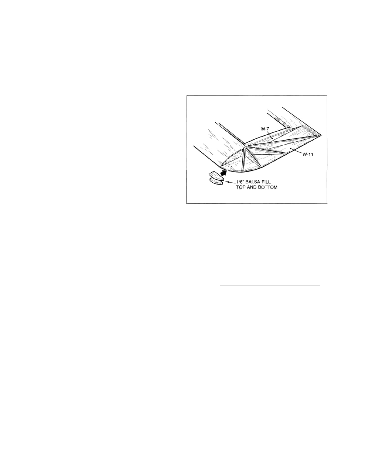
below, cut a few scraps of 1/8" balsa to
fill in the leading edge of the wing tip
and glue these in place. From the
remaining 1/16" balsa sheet provided in
your kit, cut. fit and glue in place the
wing tip braces as shown on the plans. On
our prototypes we added these braces top
and bottom.
9. With the left wing still down flat to your
work surface, locate the vertical grain
shear webs (1/16" balsa). Cut, fit and
glue these in place between the remaining
w-2 ribs. out to the polyhedral break.
10. Remove the joined wing structure from the
bench. Pin or weight the right panel in
place to the bench and glue the remaining
top spruce spar in place followed by the
remaining vertical grain shear webs.
11. As you did with the wingtip panels,
carefully shave and sand the inner panel's
leading edges to conform with the top
contours of the wing ribs. Use your
sanding block to lightly sand any high
points on the panel's top surfaces. When
done. the inner panels are ready to sheet.
Pin or weight one side or the other in
place on your work surface. Cut, fit and
glue the leading edge sheeting in place
(again leaving a bit of a "shelf" at the
rear edge of the top spar). Cut, fit and
glue the center section sheeting in place
using the patterns shown on the plans.
Finally, install all of the remaining 1/16"
x 3/16" cap strips out to and including the
polyhedral break. Repeat this procedure
on the opposite wing panel.
12. Locate and remove wing tip parts W-11 from
their die-cut sheets. Sand their inner
edges lightly to render them flat and
straight. Note the tip reinforcement
option shown on the plans. This addition
of a length of 1/8" x 3/16" spar stock
really "beefs-up" an area prone to stress
in an accident. Glue the W-11 wing tips in
place as shown on the plans ("End View of
Wing tip" left panel). Also as shown
The completed wing structure should be carefully
sanded to final shape including the leading edges.
At this point your PHASOAR's wing structure is
nearly complete. Later, after the FUSELAGE
ASSEMBLY, we will insert the forward 3/16" dia. x
1-1/2" hold-down dowel, drill the center section
trailing edge for the hold-down screw and add the
front and rear balsa wing/fuselage fairings.
VIII. STABILATOR CONSTRUCTION
Studying the plans you'll note that the entire tail
group (stabilator, fin and rudder) for your PHASOAR
consists of flat "plate" structures, which have
die-cut "core" parts and die-cut "cap" parts.
These structures are sanded to airfoil shape (shown
on plans) after assembly. Although these
structures are quite straight-forward in design, it
remains important that care be taken in cutting and
gluing the required parts together.
1. From the small parts bag, locate and remove
the single 3" length of 1/16" I.D. aluminum
tubing and two of the four 1/16" dia. x 11/2" lengths of music wire (M.W.).
Carefully measure and cut-off four(4) 5/8"
lengths of the aluminum tubing, using a
single-edge razor blade with a rolling
motion on a hard surface. Be sure to save
the remaining 1/2" length of this tubing
for later use.
6
Page 7

2. Locate and carefully remove the 3/32" die-
cut core parts S-1 (2 each) and S-2 (2
each), and the 1/16" cap parts S-3 (4
each). Make sure your stabilator plan is
covered with clear protective material and
position each of the S-1 parts in place weight or pin. Glue the S-2 parts in place
to each S-1, directly over the plans.
Remove the two resultant structures from
the plan and, holding them together,
lightly sand their outer edges to match
exactly.
3. In this step you are going to glue each of
the S-1/S-2 structures to a S-3 cap part,
a bottom left and right. Apply a thin
coating of glue to the bottom of each S1/S-2 structure, keeping it out of the
slots, and pin or weight in place over the
bottom S-3 cap. Once again, remove the two
resultant structures from your building
board, hold them together and light-sand
their outer edges flush with each other.
Re-position these parts back over the plans
and securely pin or weight in place.
4. Now test-fit each of the four (4) 5/8"
lengths of aluminum tubing in place into
the slots provided in the S-1/S-2 parts
with both of the 1/16" x 1-1/2" M.W. rods
in place. This is a good time to trim
anything that does not fit well. Refer to
drawing. Note that the two M.W. rods are
meant to be parallel with each other when
in place. Using 5-minute epoxy, glue each
tube in place into each slot in each S-1/S-
2/S-3 structure, being careful to keep glue
out of the tubes - allow to cure.
6. Cut, fit and glue the 1/4" x 3/8" balsa
trailing edges and tips in place - pin or
weight securely. From the 1/4" balsa stock
provided in your kit, cut, fit and glue the
two required tip corner gussets in place.
Again using the 1/4" balsa stock, cut, fit
and glue the leading edges in place.
7. Using the 3/32" x 1/4" balsa stock provided
in your kit, cut, fit and glue the diagonal
geodetic "ribs" in place, using the plans
as a guide. Take care here to create the
best joints that you can. Using the trim
lines shown on the right stab side, trim
the right stab tip as shown. Remove the
stabilator structures from your building
board. Holding the right stab half over
the left. trim the left stab half tip to
match the right, while still holding the
structures together, sand the rear, inboard
trailing edge "notches" per plan.
8. The stabilator halves should now be
complete and matched. Further, when joined
together with the 1/16" M.W. rods, they
should be flat in relationship with one
another. The last step is to sand these
halves to airfoil shape as shown on the
plan.
5. Apply a thin coat of glue to the bottoms
of the two remaining S-3 top caps and pin
or weight these in place directly over the
tops of the S-1/S-2 structures, carefully
lining-up the inboard edges. Remove the
two structures from your building board and
remove the two 1/16" dia. x 1-1/2" M.W.
rods and pin or weight directly over the
plans.
Note holes through geodetic ribs and root section
of stabs and a similar hole through bottom of
rudder and through top of TC-1's on fin. These are
"breather" holes for covering purposes. They allow
hot air to escape the structure, allowing MonoKote
to fully shrink.
IX. RUDDER CONSTRUCTION
1. Locate and carefully remove the two
7
required R-1 die-cut rudder cores from
their
sheets.
required 1/32" RC-1 rudder cap parts.
Start construction by gluing the two R-1
parts together, taking care to match their
outer edges with each other. Pin or weight
the
R-1/R-1
plans.
Do
the
structure
same
in
for
place
over the
the
two
Page 8

2. Cut, fit and glue the rudder's 3/16" sq.
balsa leading, top and trailing edge in
place. Glue one of the RC-1's in place
directly over the R-1/R-1 structure,
matching each edge. Locate and remove two
of the die-cut 1/32" x 3/16" x 8-1/2" fin
and rudder cap strips from their sheet. As
shown on the plans, the cross-hatched areas
at the leading edge and top of the rudder
are "capped" with this capstrip stock - do
this now. Remove the structure from the
plans and lightly sand the "capped" side
smooth. Place the structure back on your
work surface, opposite side up, and glue
the remaining RC-1 and capstrip stock in
place. Again, lightly sand this side of
the rudder smooth. Re-position the rudder
assembly in place over the plans - pin or
weight.
3. Using the 1/4" sq. balsa stock provided,
cut, fit and glue the two bottom, leading
and trailing edge corner gussets in place.
Using the 3/32" x 1/4" balsa provided, cut,
fit and glue the diagonal geodetic "ribs"
in place, using the plans as a guide.
Again take care to create the best joints
that you can.
4. Remove the rudder structure from your work
surface and use a sanding block to smooth
each of the four outer edges and the left
and right surface of each side. with the
exception of the addition of the 1/32" ply
rudder control horn and the 45-degree bevel
for hinging, the rudder is now complete and
can be sanded to the shape shown on the
plans. Set the structure aside for later
fitting to the fin.
X. FUSELAGE/FIN CONSTRUCTION
Note that the fuselage and fin, with the stabilator
drive, are constructed as a single unit.
1. Remove the two fuselage sides from their
die-cut sheet. Tape, pin or clamp them
together and use a sanding block to lightly
sand their edges, thus matching them
exactly. Remembering that a left and right
side is required, glue F-2 on the fuselage
sides as shown below on the assembly of
nose and forward fuselage drawing.
8
Page 9

2. Glue 1/4" triangular corner blocks, leaving
space for F-3 at forward edge of fuselage.
Using F-3 and F-4 for spacing, cut and glue
1/32" vertical-grain nose doublers.
Glue block in place to RIGHT T-1, just
below cutout. Insert cable into tube and
use a heat gun to bend tubing and cable to
fit within right fuse side. Once bend has
been made, glue tube to right fuse side up
to F-5 location about every inch.
3. Add 1/8" longerons and uprights per
sections E-E, F-F, and G-G.
4. Drill LEFT fuse side for rudder control
tube exit as shown, glue tube in place to
inside of left side all the way to F-5
(about every 1") - set aside.
5. Build basic fin frame directly over plans
using 3/16" x 3/16" outside frame stock.
Remove from plans; lightly sand flat.
Install antenna tube
(sections E-E and F-F).
8. Notch F-5 to accept rudder, elevator, and
antenna tubes. Notch F-4 to accept rudder
and elevator tubes.
9. Mark rear pivot hole location onto LEFT T1 side. Use a punch (nail, etc.) to open
this hole enough so that later sanding
won't remove it. Glue LEFT T-1 sheet in
place. Use the 1/32" x 3/16" stock to cap
the left side of the fin. Lightly sand
flat.
10. Lay the LEFT fuselage side over the RIGHT
fuselage side/fin assembly. Check fit.
Sides should match. Glue LEFT fuse side
to RIGHT fuse side from 1" forward of the
fin, back to the end of the fuselage weight or pin and allow to dry.
11. Spread fuse sides and glue F-5 in place keep square (5-minute epoxy allows a bit
more positioning time. Glue F-4 in place;
keep square.
to right side
6. Glue RIGHT fin sheet part T-1 accurately
in place, as shown on fin drawing. Glue
rear 3/16" Sq. pivot block in place. Glue
RIGHT side 1/32" x 3/16" fin frame cap
stock in place; lightly sand flat. Glue
fin in place to RIGHT fuselage side, over
plans.
7. Solder drive fitting to cable end. Use
3/16" x 3/16" block to hold cable tube.
12. Glue rear 1/8" ply screw plate in place
against F-5 fuse sides and against bottoms
of F-2.
13. Epoxy F-3 in place.
14. Trial-fit motor, with the ASTRO FLIGHT
Cobalt 035, rotate motor as far as it will
go to the right (this minimizes the height
of the brush housings). Note that the
bottom brush housing will contact the
9
Page 10

bottom left triangular stock. Mark with a
pencil where this occurs and use a DREMEL
to relieve this area. Once the motor is in
place, drill two 1/8" diameter holes in F3 for mounting with two 4-40 x 1/2" screws.
Remove motor and screws - set aside.
Note: For a MABUCHI 380 motor, no
special rotating is required, but metric
mounting screws are needed (not supplied).
15. Using 1/16" balsa sheet stock, glue bottom
sheeting in place (cross-grain) from rear
of F-4 back to end of fuse sides.
16. Glue 1/8" pod screw plate in place between
1/8" fuse longerons and against rear of F-
5.
17. Tack glue die-cut P-4 ply pod base to
bottom of fuse sheeting with front edge
securely against F-4. Glue forward pod
former P-2 carefully to P-4 (Keep glue off
of F-4 and be sure to center P-2). Glue
triangular 1/4" stock to bottoms of P-1 pod
sides - be sure you make a LEFT and RIGHT
pod side!
18. As shown on the plans the pod is held in
place at the front with two 5/8" lengths
of 1/16" music wire. The two required
holes for their locating/mounting pins must
now be drilled through P-2 and F-4. Drill
1/16" holes. Insert the two 1/16" x 1-1/2"
music wire pins in place and glue securely
to the P-4 pod base and P-2 former.
1/2"x 2" x 12" length of balsa. Using a
sanding block, bevel-sand one end of the
block to fit against the forward face of
F-4, holding it in place at the top of the
fuselage.
23. The forward end of the radio hatch is now
cut at the angle shown on the plans. Once
the bevel cut has been made, use the
sanding block to lightly clean up each end
of the cut. Set aside the hatch part for
a moment. On the remaining length of block
measure forward from the bevel cut and cut
this piece off. This then becomes the
forward "lip" for the radio hatch. Use
tape to hold the radio hatch in place to
the top of the fuselage, against F-4.
Apply a small amount of glue to the bottom
of the forward block and glue it in place
to the top of the fuselage and nose block,
matching the bevel on the front of the
radio hatch block, thus insuring a nice fit
between these two blocks. Untape and
remove the radio hatch block. Locate and
remove the ply hatch "lip" from its die-cut
sheet. F-4 can now be glued to the
forward, bottom surface of the hatch block
with 3/16" of its forward end protruding,
thus providing a fit beneath the forward
block just installed and preventing
shifting from side-to-side. Install the
two 1/8" square hatch locators. Repeat
procedure for the bottom nose block. The
bottom block, not being removable, can now
be glued in place.
19. Now glue the P-1 pod sides in place to P2/P-4 making sure the P-1's match the
fuselage sides. Make certain to keep glue
off of fuse sides. See drawing below.
20. Glue 1/8" x 3/8" spruce/ply to bottom of
P-4 and butt up to P-3.
21. Fit and glue P-6 and pod tail blocks in
place. Drill cooling air outlet holes and
sand bottom of pod to accept P-5.
22. Now drill and tap pod screw plate with an
8-32 tap. Glue P-5 in place. Locate the
24. The next step is to assemble the nose
block. Glue the plywood spinner ring to
the 1/4"x 1-3/4" x 2" balsa nose block,
carefully centering it. After the block
has dried, remove center section by cutting
along center of spinner ring with a #11
blade. Sand the front of the fuselage per
section B-B to accept the nose block
assembly. Align the nose block with the
motor shaft and cement to F-3. The coolair intake hole can be drilled at this time
(see photo below).
10
Page 11

25. Now trial-fit your wing to the fuselage.
Make sure the wing is centered and that the
leading edge is up against F-4. Holding
these two structures together, observe the
fit between the bottom of the wing and the
wing saddle area. It may be necessary to
slightly bevel the tops of the fuselage
sides and F-1 doublers to get a snug fit;
do this now. Once satisfied with the
wing/fuselage fit, you're ready to make the
hold-down system. Again place the wing on
the fuselage and use weights to hold it
firmly in position. Make sure that the
wing is squarely in position on the
fuselage by taking wingtip-to-tailpost
measurements as shown in the figure below
("X" should equal "X").
the threads have been cut, give them a very
thin coat of instant CA glue and again run
the tap through them. This toughens the
threads in the plywood. Re-fit the wing to
the fuselage and screw it in place to again
check the fit. Note that about 7/8" of the
length of the nylon screw (1-1/2" supplied)
can be trimmed off.
26. Remember that 1/2" length of 1/16" I.D.
aluminum tubing that you saved back when
building the stabilator? Locate it now.
with a 3/32" drill bit, finish the hole
through the fin (the stab pivot hole). Cut
a 1/4" length of aluminum tubing, clean
each end with a #11 blade and carefully
insert it into the stab pivot hole just
cleared out; do not glue. Attach the
stabilator halves to the fin; just press in
place for now. what we're going to check
for now is alignment, we want to view the
airplane head-on at a bit of a distance.
Place it on a table, facing you, and backoff a few paces, sighting directly at the
front. Is the wing sitting properly on the
fuselage? Is the stabilator tilted in
relationship to the wing/fuselage or does
it line-up right? If everything else seems
to line-up, we can proceed to finish
sheeting the top, rear of the fuselage. If
it doesn't, we need to know which way to
twist the fin to make everything line-up
properly because once the top, rear
sheeting is installed, it "locks" the
fuselage firmly in place thus making any
such corrections extremely difficult, if
not impossible.
Locate the 3/16" dia. dowel from the parts
bag. A 3/16" dia. hole must now be drilled
through F-4 (see mark) and into the wing's
center w-1 ribs, to a depth of 1-7/8,"
measured from the front face of F-4. Mark
this depth on your drill bit with a strip
of tape. Once the hole is drilled, remove
the wing from the fuselage and trial-fit
the 3/16" dia. dowel in place. Use
sandpaper to slightly round the front edge
of the dowel. Now glue the dowel in place
in the wing (clean off any oozing glue).
Once dry, again fit the wing to the
fuselage and use weights to hold it in
place. The rear nylon screw hold-down
system is now made. Start by drilling a
hole, with a #29 drill bit, through the
wing's trailing edge and through the 1/8"
ply wing screw plate at a slightly forward
angle (see plans). Remove the wing from
the fuselage. Enlarge the hole in the
wing's trailing edge to allow the 8-32
nylon screw to slip through to the head.
Now using either an 8-32 tap or an 8-32
screw (metal), tap the threads into the
hole made in the ply wingscrew plate. Once
27. If the alignment appears to be OK, remove
the stabilator halves, leave the wing in
place, and carefully cut and glue the 1/16"
balsa sheet (applied cross-grain, as shown)
top, rear decking in place back to the
leading edge of the fin. However, if some
alignment is needed by having to pull the
top of the fin left or right, now is the
time to do it, before applying the top,
rear sheeting. This is how it's done. Set
the assembled airplane on a large, flat
table. Height the top of the wing center
section to hold it firmly in place. Again,
sighting directly at the front of the
model, determine which way the fin has to
be tilted. Pull off a long length of
masking tape and stick it to the top of the
fin. Pull against the tape until the fin
is in the right position and stick the
other end to the table, thus preventing the
fin from shifting. With it now properly
aligned, cut, fit and glue the top, rear
sheeting in place as earlier described.
Let the sheeting dry before removing the
masking tape from the fin and you'll find
that the fin is now properly aligned.
Remove the wing and stabilator halves from
11
Page 12

the fuselage. Use your sanding block to
now sand the top, rear sheeting and the
forward radio hatch and nose block piece
flush with the fuselage sides. You can
also now sand the top forward hatch and
nose-block contours to shape as shown in
the plans, no need to round corners yet.
28. From your parts bag, locate the 1/4" shaped
fin/fuselage fairing. Use your sanding
block to adjust the angles if needed and
glue in place. As shown, this is now
trimmed to fair the fin leading edge into
the top, rear of the fuselage.
handled this by sticking a length of
masking tape lengthwise about 3/16" above
this joint, on T-1. Then we carefully
sanded down the fuselage side(s) to as
close to T-1 as possible (the masking tape
was there to protect T-1 in case we got too
close). Then with the tape still in place.
we used filler to "fair-in" this joint,
feathering the material carefully. When
the filler was dry, the tape was removed
and we used very light sandpaper to finish
feathering the joint.
29. Finally, push the 1/4" length of aluminum
tubing that's in the rear pivot hole about
halfway out, apply just a bit of adhesive
to its outer surface (5-minute epoxy or
slow-cure CA) and push it back in place in
the fin.
30. with the exception of contouring and final
sanding, your fuselage should be complete.
XI. FINAL ASSEMBLY
It's often been said that the difference between a
good model and a great one is sandpaper and the
willingness and ability to use it. This point in
construction can literally make or break the
performance and the look of your model. Since the
PHASOAR is an obvious candidate for use of
MonoKote, keep in mind that the surface preparation
of the wood will dictate the finished, covered look
of your model. Referenced use of "filler" in the
following text. refers to products such as
MicroFill, Model Magic Filler, or something
similar. These products dry quickly, are very
light, and MonoKote goes over them nicely.
Let's start with the fuselage, since the other
components should, by now, be sanded and about
ready to use.
1. Note the lower left corner of Cross Section
F-F on the plans. This demonstrates about
the correct amount of radius that can and
should be sanded into the fuselage bottom.
As this sanding radius moves aft, toward
the fin post, and the fuselage diminishes
in width, the result will be a pleasant
looking oval shape. Next, sand the radio
hatch and nose sections. Use a rougher
grit of paper at first, followed by the
finer #220 to do the job nicely. The last
section to tackle is the top, rear of the
fuselage - back and including the fin
fairing and fin leading edge. Take every
effort needed to sand this structure to the
point that it looks and feels like one
piece. You will note that where the T-1
fin sides meet the fuselage sides, there is
a disparity in wood thickness resulting in
a kind of "tip." On our prototypes we
2. Use your sanding block to sand the trailing
edge of the fin flat and straight.
3. The last step in preparing the fuselage for
covering is to sand the fin/rudder
combination together, as a single unit.
Start by using masking tape to accurately
position the rudder to the fin. Now use
your sanding block to accurately match the
side view shape of the rudder to the
fin/fuselage. Once that's done, remove one
of the pieces of tape from one side only
and lay the structure down on a flat
surface - taped side down. Use your
sanding block to now sand the rudder's
cross-section shape into the fin/fuselage,
but only about halfway. Add another piece
of tape to the now sanded side, flip the
structure over, remove the tape and repeat
the sanding operation. After a couple of
passes on each side, you should be about
where you want to be; a fin with a true
leading edge and a rudder with a true
trailing edge and everything in between
accurately matched. The leading edge of
the rudder can now be beveled as shown on
the plans, thus facilitating left and right
movement when hinged with MonoKote.
Once this is done, locate and remove the
1/32" ply rudder horn from its die-cut
12
Page 13

sheet. Once again tape the rudder to the
fin, right side only. Use a sharp #11
blade to now cut a 1/32" wide slot in the
rudder's leading edge, at the bottom, on a
plane corresponding to the rudder tube's
exit point on the fuselage. Once the slot
is made to your satisfaction, trial-fit the
horn in place and trim as needed to get a
proper fit. Do not glue the horn in place
until after the model is covered.
4. Assemble the wing to the fuselage and cinch
it down with the wing screw. In this step
we want to rough-cut and fit the forward
and rear wing/fuselage fairings to the
wing's center section. The remaining
length of radio hatch block balsa will be
used for this. First either carve or use
a Dremel tool to route out the bottom
mating surface of each of these blocks; cut
and fit. Bevel the rear block to match the
fuselage (viewed from the side) and then
use your #11 blade to carve out a space for
F-12 when the block is held in place.
Also, the head of the screw will indent the
bottom of this block and therefore give you
the location to drill a 1/4" dia. hole to
allow the screw head to seat against F-12.
Once you're satisfied with how the two
blocks fit onto the wing and to the
fuselage, concentrate on the top view. The
forward should be sanded to a sort of halfround shape, carrying through the shape of
the hatch block. The rear block gently
curves in to the center line of the wing to
a point about 1-1/2" from the trailing
edge. Glue the blocks in place to the top
of the wing while the wing is still
attached to the fuselage. Protect the wing
sheeting around the edges of these blocks
with masking tape; sand to a final shape.
Use filler to fillet the blocks to the
wing. Lightly sand, and you're finished.
Remove the wing from the fuselage.
5. Use a sharp razor blade to remove the
finished radio hatch block. With the
battery/servo compartment now open, install
your servo mounting rails. Note on the
plans that we've used the remainder of the
1/8" x 3/16" spruce spar stock for these.
You may wish to use ply. Install these
rails in the approximate positions shown on
the plans, with the servo's output arms
lined-up with the rudder and elevator tube
ends protruding through F-4. with servos
in place, cut the 1/4" x 3/8" x 4" spruce
micro switch mount to fit as illustrated
on the drawing. Drill and attach the two
1/4" x 1/4" x 3/8" maple blocks to the
mount with #2 x 3/8 wood screws. Next
drill two holes in the mount for the micro
switch, and mount with two 2-56 x 1/2"
screws and nuts. Set the assembly in
position as shown on the drawing. When
proper contact is made with switch and
servo arm, glue in place. Once satisfied,
servos can be removed.
6. Before covering take a few minutes to
"ventilate" the various structures; wing,
fin (above T-1's), stab halves and the
rudder. Ventilating these components
allows the heated air (formed when
covering) to escape the various sealed
compartments (between rib bays, etc.)
rather than expanding and "ballooning" the
covering.
7. For the wing, use a 3/32" dia. drill bit,
hand-held, to drill one hole through each
rib, in the center, just behind the spar
location. Do this from W-7, at the tip.
all the way through the inner-most W-2 rib,
beneath the center section sheeting. Using
the same bit, drill a hole through the
bottom sheeting, just behind the spars on
each side of the W-1's.
8. Use a 1/16" dia. drill bit, again handheld, to now do the same thing to the fin
(and also through the 3/16" sq. brace
between the tops of the T-1's), rudder and
stab halves. On the rudder, drill a small
exit hole on the very bottom, behind the
horn location. On the stab halves, drill
the exit holes through the rear diagonal
3/16" sq. piece.
9. Final-check entire airplane for any flaws
or problems. If you find any, fix them
now.
10. Since the stabilator halves slip in place
using two 1/16" dia. steel pins, there is
a need to be able to retain them. This can
be done a couple of ways. The first is to
simply allow the pins to rust by leaving
them outdoors for a night or two. This
makes them press-fit into the stab half
tubes. Another way is to use a low-tack
adhesive (3-M #77 Spray Cement) to coat the
wires, thus making them a bit "sticky." In
any event, don't permanently glue these in
place since eventually the need will arise
for disassembling the stabilator halves
from the fin.
13
Page 14

XII. MOTOR/SWITCHES/BATTERY
WIRING
CAUTION
FAILURE TO READ, UNDERSTAND, AND THEN FOLLOW THESE
INSTRUCTIONS CAN RESULT IN SERIOUS PERSONAL AND/OR
PROPERTY DAMAGE TO YOU OR OTHERS!
WHEN OPERATING THE MOTOR:
* ALWAYS wear eye protection!
* KEEP safely away from others!
* ALWAYS make sure the propeller is securely
attached to the motor drive shaft!
* REMEMBER to always use the arming switch
correctly!
fuse. A fused electrical system offers some real
safety to its overall operation. Should the motor
stall, as in the case of the propeller being
stopped due to striking an object, the battery pack
will surge its current output and blow the fuse,
thus preventing motor and/or battery pack damage or
burn out.
HIRING
These instructions concern the required wiring when
using the ASTRO FLIGHT 035 Cobalt motor. The
components of this system (as shown below) are:
* WARNING:
Children should never be allowed
to operate this equipment without
adult supervision!
CAUTION: POTENTIAL BATTERY HAZARD!
The Ni-Cad battery packs used to power the PHASOAR
store a great deal of electrical energy. Always be
extremely careful to avoid shorting out these
batteries. This can lead to a fire, cause burns to
you and others and/or, at the very least, ruin the
battery pack.
CAUTION: PROPELLER HAZARD!
The suggested motor/battery/propeller components in
these instructions result in an extremely powerful
system. The arming switch system should be
properly notated to provide ON/OFF information.
When switched ON, the motor, instantly reaches
maximum RPM's and the spinning propeller becomes a
hazard to you and others, treat this system with
respect! It is very important that you understand
all of these precautions and take steps to prevent
accidental switching-on of the system. Always
unplug and remove the motor battery pack when
storing the model or working on it. Always store
the model away from small children or anyone else
unfamiliar with its correct and safe operation.
REMEMBER: Install and connect the motor battery
pack ONLY when the arming switch is in the OFF
position and the micro switch is inactive.
IN ANY OTHER SITUATION, always disconnect and
remove the battery pack, especially when working on
the model and transporting or storing it.
FUSES
In the following instructions there is a straight-
forward wiring diagram which also includes a
notation concerning the location of a 15 to 20 amp
* 10-1/2" of Red (positive, +) hi-flcx, hi-
strand count wire (we've used both R06ART
and SR wire with good results).
* 12-1/2" of Black (negative, -) wire.
* Micro switch (Subminiature SPDT Lever
Switch) made by ARCHER and sold through
RADIO SHACK stores - Catalog No. 275-016.
* Arming switch (Subminiature SPST Toggle
Switch) made by ARCHER and a RADIO SHACK
item - Catalog No. 275-612.
* 1 Package of SERMOS R/C CONNECTORS
(contains four connectors, 2 red and 2
black).
* Soldering Iron or Gun (about 42 watts).
* Flux and solder.
* Small 15-20 amp fuse with solderable
holder.
14
Page 15

1. The ASTRO FLIGHT 035 cobalt motor comes
already pre-wired with a Tamiya-type
connector and an RF choke soldered in
place. Start by un-soldering the black
wire from its post connector, leaving the
RF choke joint still in place.
Referring to the diagram above, cut a 4-
1/2" Length of hi-flex wire and use a razor
to remove about 1/4" of the sheathing from
one end. Bend the solder tab straight out
from the post on the motor. Now solder the
wire to the tab with the length of the wire
pointed forward, towards the front of the
motor. Bend the solder tab back down
again. Cut this wire in half, remove the
sheathing from each end and solder the
fuse/holder in place. The remaining end
of this length of wire is now soldered, in
place to the center solder tab on the micro
switch, with the wire in place straight
down, in relationship to the switch.
2. The remaining length of black (-) wire
(should be 8") is now prepared by first
removing 1/4" of the sheathing from each
end. Now solder the SERMOS connector clip
to one end and insert and snap the black
connector in place. The other end of the
wire is now soldered in place (wire
pointing straight down from the switch) to
the far left solder tab of the micro
switch. This completes the negative side
wiring.
each solder joint, making sure they are
each secure. Applying a small amount of
silicon adhesive to each of these joints
further avoids any shorting.
4. The wiring system and switch array should
now be tested. Assuming that your battery
pack has been equipped with SERMOS
connectors, connect the pack to their
appropriate leads. Hold the motor firmly
in your hand (WITHOUT A PROP IN PLACE) and
"blip" the micro switch with the arming
switch in the ON position. If nothing
happens (highly unlikely), your battery
pack is either totally dead (discharged) or
you have a cold solder joint somewhere.
Now is the time to again check all of these
connections to ensure proper operation
every time, on demand.
XIII. COVERING
In every aspect of these instructions thus far,
we've stressed the importance of paying attention
to weight. At this point in the construction of
your PHASOAR, you should have an amazingly light
model. In keeping with this attention to weight,
it is extremely important that you cover your
PHASOAR with MonoKote. MonoKote will provide your
PHASOAR with comparatively little weight gain, an
incredibly brilliant finish and most importantly-airframe strength!
Realistically, one 6' roll of MonoKote, properly
cut-up and applied would do the job, providing you
would settle for a mono-chromatic color scheme.
However, you may consider a multi-colored scheme
that is at once visible in the air and looks great
in the pit area, too! Now is the time to choose
your favorite MonoKote color combination.
MonoKote is easiest to apply and work with when you
have the appropriate tools at hand to do the job.
3. Now un-solder the remaining red wire on the
motor's solder tab, again leaving the RF
choke connection in place. Cut a 5" length
of red hi-flex wire and remove 1/4" of the
sheathing from each end. Solder one end of
this wire to the motor's solder tab with
the length of the wire pointing forward
toward the front of the motor. Bend the
tab back down. Solder the remaining end of
this wire to the "ON" solder tab of the
arming switch. The remaining length of red
wire (should be 5-1/2") is now prepared by
again removing 1/4" of sheathing from each
end. Solder one end into the SERMOS
connector clip and insert and snap the
connector (in this case red) in place. The
remaining end of the red wire is now
soldered in place to the "OFF" solder tab
of the arming switch. Clean and inspect
15
Page 16

Shown in the photo above is a collection of Top
Flite tools, the Hot Sock iron shoe cover (a
"must" for a great finish), MonoKote
Cleaner/Polish, a selection of MonoKote, razor
blades (single edge), a hobby knife with a #11
blade and a metal straight-edge (min. 36" long).
The best practice is to cover each of the
aircraft's components separately. In the case of
the PHASOAR, this means the wing, the fuselage, the
battery pod, the stabilator halves and the rudder.
After covering, carefully clear-out any of the
required holes, slots, etc., that may have been
covered up, i.e., rudder horn slot. stabilator
drive ovals, pivot holes, antenna tube exit, and
rudder cable drive exit, etc.
From
your
parts
bag,
locate the 1-1/2" long,
0.038
I.D. brass tubing. This material will be cut up to
provide solder connections between the drive cables
and the soft wire paper clip connectors.
Drill a 1/32" dia. hole through the rudder horn to
accept the paper clip drive wire. Cut off about
1/4" of the brass tubing connector material and
clean out each of it with your #11 blade to accept
the cable and paper clip ends. Cut off the
required length of paper clip wire (see plans) to
make the connection to the rudder horn and bend one
end into a "Z" bend. Slip the brass connector
halfway onto the drive cable end and the paper clip
wire into the other end of this connector. Sweat
solder the three pieces together, using a minimum
of solder. Slip the opposite end of this drive
cable into the rudder tube and feed its length
through the fuselage and into the servo compartment
- don't cut off the excess cable yet. Attach the
rudder horn to the "Z" bend and carefully glue the
horn into the slot previously provided.
The connections made at the servo ends of the
stabilator and rudder drive cables are done in the
same manner as described above. However, the paper
clip connectors are to be bent with a "V" bend as
shown, thus providing some centering adjustments
for flight trim.
On our prototype PHASOAR"s we used a small brush
and some flat black paint (aircraft dope is fine
here) to paint the inside of the air entry hole in
the nose and the hole in the rear of the battery
pod. This is not necessary, but looks quite nice.
The rudder can now be hinged to the fin using the
method shown on the plans. This hinge system
provides an extremely efficient rudder action in
flight by virtue of the fact that it is gapless.
Properly done, these hinges are all but invisible
and lend greatly to the overall "one-piece" look of
the finished model. Do not install the rudder horn
in place yet. This will be done in the RADIO
INSTALLATION section of these instructions.
With your covering job now complete, make it really
shine by giving it a glistening cleaning job with
a few shots of MonoKote Cleaner Polish! About all
that's left to do is to add your AMA numbers.
REMEMBER that these have to be 1" or taller and
must appear on the RIGHT wing panel, we have used
both Super MonoKote and MonoKote Trim Sheets for
this job to make it easy and good-looking.
XIV. RADIO INSTALLATION
Before
installing
run in the right directions. If you have servo
reversing capability, this is a simple task.
Install
the
provided earlier.
servos
your
in
servos,
the
fuselage
make
sure that they
on
the
rails
Install the receiver next. To get the antenna
through the fuselage and out the hole previously
drilled for this purpose, "fish" a length of heavy
thread through the antenna exit hole and into the
receiver area. Then use a bit of CA glue to attach
the end of the antenna to the end of the thread and
pull the thread back out of the antenna hole. along
with the antenna.
The battery pack should now be installed, as shown
on the plans, and held in place with double-backed
tape. The ON/OFF switch can also be held in with
double-backed tape. With everything in place, turn
the system ON and test for correct movement and
centering. Adjust as needed.
The "CG" (Center of Gravity) shown on the plans is
exactly where we've flown our prototypes. Balance
your model at this point. Interestingly, our
prototypes did not require any lead at all to
arrive at the CG shown.
XV.
THE FLYING SITE
FLYING
Where there is no established local flying site, a
large, grassy field can be an ideal area. This
field should be free of trees, poles, large
obstructions and. especially, high-tension
electrical lines. Always fly far removed from
houses, populated areas or busy streets. An area
approximately two to four times the size of a
16
Page 17

regulation football field should provide you with
plenty of room, especially when attempting your
first few landings!
As we mentioned in the introduction, there is
simply no substitute for an experienced R/C pilot
to check-out, trim and test-fly your model! This
almost always is a guarantee of success. Remember,
if you have no experience you NEED an instructor!
Just as you did in the test-gliding phase, hold the
model high over your head, level or nose slightly
down, pointing to that imaginary point 100' ahead
of you and directly into the wind. With the
transmitter in your other hand, move the throttle
stick up to the ON position and trot or run
forward. When it feels right, smoothly throw the
model forward, wings level, toward that imaginary
point. Immediately take the transmitter in both
hands for control.
PRIOR TO POWERED FLIGHT
First, test-glide your model at least a couple of
times.
With the "throttle" stick and also the arming
switch in their OFF positions, turn the transmitter
ON. Now turn the model's airborne radio ON. Test
the controls with the transmitter, once again, to
be absolutely sure the controls are moving in the
proper direction!
Stand facing into the wind, if any (it's best if
there is none), hold the model high above your head
in a LEVEL position, with the transmitter in your
other hand. Trot or run forward to build up
"flight speed." When it feels right, briskly throw
the model directly forward (level) at an imaginary
point about 100' in front of you. In other words.
DO NOT pitch the model into the air in a nose up
condition! The model should glide smartly toward
that imaginary point without any tendency to veer
left or right. If it is turning, correct with
SMALL amounts of transmitter input to the opposite
side of the turn. If the model wants to pitch up,
correct quickly with SMALL amounts of DOWN elevator
input and if the model pitches down, correct
quickly with SMALL amounts of UP elevator input.
Just prior to touch-down, a SMALL amount of UP
elevator input can be used to "flare-out" to a
smooth landing. Continue this process until you
can consistently achieve the required flat, smooth
glide. Take your time here to get comfortable with
this phase of your model's regime because
ultimately the glide will constitute the bulk of
its flying time.
Typically, the PHASOAR will quickly get into
and
start an aggressive
momentary SMALL inputs of DOWN elevator to control.
Keep the model climbing out, into the wind and away
from you until it is about 400' away. At this
point, the model will be quite high and you can
start a slow 180 degree turn back toward you, still
allowing the model to climb out. Before it gets
back to you, do another 180 degree turn. Repeat
this process until comfortable altitude is reached
(with our prototypes, uncomfortable altitude...too
high...was reached in less than 55 seconds). Move
the throttle stick to the down or OFF position and
let the model transition into glide mode. This
first flight is for experience purposes only and
not dedicated thermal hunting so don't be concerned
about
looking
totally comfortable doing so.
With the PHASOAR now in un-powered glide,
familiarize yourself with each of the controls.
REMEMBER: This design is a powered sailplane, not
a pattern ship. Save the aerobatics for a
different design! Check for stall characteristics,
both upwind and downwind, by simply establishing a
heading and slowly pulling back on the elevator
stick. What should happen is nothing more exciting
than a nose-high attitude, followed by a nose-down
pitch with almost immediate recovery. If the model
wants to fall off briskly to one side or the other
(a
"tip stall"), you are going to want to impart a
little "washout" to each outboard wing panel when
you get home. Do this by twisting the wingtip to
raise
the
and then reshrink the MonoKote to maintain the new
position.
for
trailing
lift
edge
climb
that
right
now.
slightly
will
unless
(1/16
only
you're
to
1/8"),
"step"
need
POWERED FLIGHT
This is it! The pay-off for the work done thus
far! Just as you did before in the test-gliding
phase, activate the required switches in this
order:
1. Transmitter switch ON with throttle stick
down in the OFF position.
2. Make sure arming switch is OFF.
3. Turn airborne radio system ON.
4. NOW turn arming switch ON.
Again, test the FLIGHT CONTROLS of your model with
transmitter input to each. Holding the model away
from you (and others) move the throttle stick up
briefly to test the motor and then turn it off.
As your model gets down to 100-200' of altitude,
turn it into the wind and move the throttle stick
up to the ON position and power your way back up to
comfortable altitude and again shut down the motor.
LANDING
Land the PHASOAR by letting it glide smoothly
forward (very little, if any, elevator inputs) in
a pre-determined and large rectangular pattern
which terminates with the model pointing directly
into the wind, passing safely in front of you at an
altitude of 8' to 10.' At this point, the model is
heading away from you with the bulk of the field
ahead of it. Keep the wings level and slightly
"flare" the model (apply a touch of UP elevator)
17
Page 18

just before touchdown. Wind conditions can
profoundly influence flying and landing
characteristics. It is strongly suggested that you
do not fly this model in any wind above 5 mph until
you are totally comfortable in controlling it! The
PHASOAR has performed well in very stiff breezes
BUT only in the hands of very experienced and
competent R/C pilots. DO NOT EXCEED YOUR
EXPERIENCE AND/OR LIMITATIONS!
Take it easy and have fun!
XVI. KIT SPECIFICATIONS
The final specs on our prototypes turned out as
follows:
Wingspan
Wing
Weight
Aspect
........
Area.
.......
.........
Ratio
......
56
1/4"
335
sq.
24
to 27 oz.
9.9 : 1
in.
Overall Length ..... 32"
18
Page 19

BILL OF MATERIALS
TOP FLITE MODELS
PHASOAR 035
Kit Part
No.
RC-38- 1
59
RC-38-21
22
23
24
25
2
3
4
5
6
7
8
Computer
No.
390005
312019
312010
312020
312021
710114
312023
312024
511063
312030
390006
710115
710116
312022
312028
312029
Description Kit
Wood
D/C
D/C
D/C
D/C
D/C
D/C
D/C
Balsa Sheets
Balsa Sheet
Bundle #1 of 2
of
2
Balsa
Balsa
Balsa
Balsa
Plywood
Balsa
Balsa
Fuse sides
Wing
ribs
Fuse/Wing/Pod
Fin/Rudder
Fuse/Pod/Wing
Stab Caps
Fuse (F-2)
Wing/Fuse
Fuse Nose
Wood Bundle #2 of 2
Contains assorted balsa and spruce,
braided cable and plastic tubes.
All are rolled inside the plan sheet,
Separate Wood parts
D/C Plywood
D/C Plywood
Shaped Balsa
Shaped Balsa
Shaped Balsa
Fuse Former
Motor Mount
Pod Blocks
Fuse Nose
Hatch/Bottom Fuse
Qty/
1
2
2
1
1
1
2
1
5
1
RC-38-20
RC-38-41
380004
150026
150027
Poly Bag #1 of 1
Miscellaneous small wood parts.
Also, screws, nuts, tubing, and wire
Plan sheet
RC-38 Instruction Manual
19
 Loading...