

Page 1
Biplane
RC-37 INSTRUCTION MANUAL
INTRODUCTION
The Elder Biplane is the third
design based on the popular
Elder-series of models. This
design is a direct result of popular
demand and it surely is the
largest model of the three. Your
Elder Biplane packs a huge wing
area of 1492 square inches, that's
10.3 square feet of lifting surface!
This means that when the model
is built within the expected
weight range of 7-1/2-8-1/2 pounds,
the resulting wing loading range
would be
square foot! It also means that if
you went with the heaviest engine
available and went crazy in the
detailing and finishing aspects of this model and managed to get the weight up to 10 pounds, the wing loading
would still only be 15.4 ounces per square foot!
All of the above allows your Elder Biplane to be powered
by a very wide range of engines. This design has been
tested quite successfully using 2-stroke engines as small
as .45 and on up to .75's. For 4-stroke work, we suggest
engine sizes of .60 to .90 in displacement. Like its smaller
counterparts, the real "kick" of this design is its extremely realistic flight characteristics. Slow fly-bys are breathtaking without the fear of losing aileron authority. Landings and take-offs are absolutely effortless. In the airyour
Elder Biplane is fully capable of some of the most realistic
aerobatics you've ever seen! You can expect beautiful
loops, stall turns and snap rolls, all at speeds that actual-
ly allow you to watch the airplane instead of a "blur".
Your Elder Biplane is a rugged design that will operate
11.6 - 13.1
ounces per
very nicely out of dirt, grass or paved flying fields. The unique, shock-absorbing landing gear, proto-typical of the
Elders era, really works to smooth out even the bumpiest
of fields. With its thick airfoil section and generous wing
area, your Elder Biplane will not tend to build-up excessive airspeed. This characteristic keeps the relative
inertia low and means that crash damage is kept to a
minimum.
Like otherEIders, the Elder Biplane lends itself to all kinds
of detailing, if you're so inclined. For the beginner,
nothing fancy is needed; just fly it and enjoy. For the
builder with an imagination, the Elder Biplane can be
detailed to such a degree that other pilots at your field will
swear the airplane is a scale model! In the COVERING &
FINISHING section of these instructions there are some
ideas for detailing that might be of interest, please take
the time to read them.
TOP FLITE MODELS INC.
2635 S. WABASH AVENUE • CHICAGO, ILLINOIS 60616
Page 2

Earlier we touched on engine recommendations. Your
Elder Biplane kit contains a high-quality filled nylon motor
mount that will work with some of the engine suggestions
or this design, but not all. If the engine choice for your
Elder Biplane will not work with this mount, it might be
necessary to visit your local retail hobby shop to obtain
the correct motor mount for your engine.
IMPORTANT NOTE:
TOP FLITE MODELS, INC. Would certainly recommend
the Elder Biplane as a first R/C powered aircraft.
However, if you are a beginner to the sport of R/C flying,
we would urge you to seek and use experienced
assistance in constructing and flying this airplane.
Again, if you are new to this hobby, consider this:
Flying this or any other radio-controlled model aircraft
a
PRIVILEGE and not a RIGHT and this privilege begins
with the utmost safety considerations to others and
yourself as well. An R/C model airplane in inexperienced
hands has the potential of doing serious personal or property damage. These safety considerations start at the
building board by following instructions, seeking com-
petent help when you are confused and avoiding shortcuts. These considerations have to be carried overto the
flying field where safety must come first and limitations
cannot be exceeded. We urge you to:
1.Send for and obtain your AMA (Academy of Model
Aeronautics) membership which will provide insurance for your R/C activities — DO NOT RELY
HOMEOWNERS INSURANCE.
ON
2. Join an AMA sanctioned R/C flying club in your area
where you can obtain competent, professional instruction in trimming and learning how to fly this
model.
Check with your favorite local hobby shop for the required AMA forms or the address where they can be obtained.
WARNING!!!
A radio controlled model is not a "toy." Care and
caution must be taken in properly building the
model, as well as in the installation and use of the
radio control device. It is important to follow all
directions as to the construction of this kit as well
as installation and use of the engine and radio
gear. The advice and assistance of a well ex-
perienced builder and pilot is highly recommended. Don't take chances! Improper building, operation, or flying of this model could result in serious
bodily injury to others, yourself, or property
damage.
PRE-CONSTRUCTION NOTES
The Elder Biplane, like other Top Flite kits employs the
use of die-cut wood to ease the task of construction,
parts fit and identification. The dies used for this kit
have been rigorously checked for absolute accuracy
and should provide you with excellent fit. Die-cut parts
should be carefully removed from their sheets by first
lightly sanding the back of each sheet of parts and then
carefully removing each part. Use a light garnet paper
for the sanding and keep a sharp hobby knife with an
X-acto #11 blade, or equivalent, handy for assistance in
removing any parts that might not have completely cutthrough by the dies. Parts which oppose one another
and must be precisely uniform—such as fuselage sides,
ribs, etc.—should be carefully "matched" after their
removal from the part sheets. Matching is the process of
holding the opposing pieces together with either pins,
tape or spot gluing and lightly sanding the edges of the
parts until they are identical. A sanding block with light
garnet paper is most useful for this and other phases of
construction.
is
Your building surface should be at least large enough to
accommodate the wing panels. This surface should be
as absolutely flat as possible and yet be able to accept
pins easily. We have found that a product such as
Celotex fiber board works quite well for this purpose.
Anothergood surface can be found in most well-stocked
hardware stores-a 2'x4'fiberboard ceiling tile. These
are quite inexpensive and can be used for several
airplanes before needing replacement.
As with most R/C kits that are constructed from wood, a
selection of tools - most of which can be found in the
average workshop - are a must to do the job correctly:
• Hobby knife and sharp #11 blades
• Single-edge razor blades
•T-pins
• Sanding blocks in assorted sizes
• Sandpaper in various grits
• Hand-held hobby saw, such as an X-acto
• Dremel tool or power drill and assorted drill bits
• Straight-edge, preferably metal, at least 36" long
• 90" triangle
• Soldering iron, flux (silver) and solder
• Carbide cut-off wheel for wire cutting
• Small power jig-saw, such as a Moto-Saw
• Razor plane
• Tapes, such as masking and cellophane
Our Elders were constructed using a variety of
common hobby adhesives including 5-minute epoxy,
cyano-acrylates, and 1-hour epoxy. Since all of us have
our own construction techniques and favorite
adhesives, stick with the ones you are familiar with and
prefer. However, in certain areas there will be callouts for
certain types of adhesives, and we urge you to try not to
substitute since doing so could possibly cause
problems structurally.
The last thing we should touch on before we begin
actual construction is the sequence in which the Elder is
assembled. The sequence given to you in this booklet
has proven to be the most straight-forward and provides
the finished components in the order in which you will
need them to progress to the next assembly phase. Try
to stick with the building order presented here to avoid
mistakes.
2
Page 3
Spread the plans out on your work surface, cover them
with a clear plastic material, such as the backing from
a roll of MonoKote® or plastic wrap and commence
construction.
UPPER WING ASSEMBLY
Wing construction for your Elder Biplane consists of
building three separate pieces for each wing; the two
panels and the center section. Note that the upperwing
panels will be joined to the upper center section in the
following sequence, without the top, inboard ends
sheeted. This sheeting will be done in the FINAL
ASSEMBLY section of the manual. In this and other
building sequences, be certain that you are working on a
flat work surface. Carefully join the plans for the TOP
LEFT WING and the TOP RIGHT WING, Plan Sheets 5
and 6, at the center line provided and accurately secure
with tape. This provides the full wing plan on which to
work. The wing will be built directly over the plans, so
cover them with MonoKote backing or clear food wrap.
1. Start with the center section first. Locate the die-cut
sheets containing parts W-11 (2, ply), W-12 (2, ply).
W-13 (1, balsa), 4W-1 A's and 4 W-1 B's. Remove these
parts from their sheets and clean up any rough
edges before assembly
2. Using the plans as a guide; measure, cut and butt-
glue
the 1/4" x 1-1/2" lower leading edge, 3/32" balsa
sheet and the 3/32" x 1" trailing edge that makes up
the bottom of the center section. Note grain
direction of these pieces. Measure, cut and glue in
place the 3/8" x 1/2" upper leading edge. Glue one of
the W-11 ply dihedral braces in place against the
inside surface of the leading edge—be sure that it's
centered. Glue the outer W-1A half-ribs in place
against the rear face of the dihedral brace, lined-up
with the edges of the bottom sheeting at right angles
to your work surface. Now glue the two remaining
W-1A's in place, using the "tick" mark locations on
the plan.
3. As shown, the main dihedral brace system is a
composite made by laminating the two W-12's (ply)
to each side of W-13, which results in a 1/4" thick
part—do this now. Glue the completed dihedral
brace in place to the bottom sheeting and up against
the rear edges of the fourW-IA's. Be sure this part is
centered.
4. From your kit box, locate a piece of 1/4" x 1/2" spar
stock and cut two 5" lengths. Glue one of these
pieces in the top rear slots in the W-1 A's and against
the top forward face of the center dihedral brace.
Glue the other on the bottom sheeting against the
bottom rear face of the dihedral brace.
5. Now glue the fourW-1B rear half-ribs in place behind
the main dihedral brace. Glue the remaining W-11
(ply) dihedral brace in place on the bottom sheeting
and against the rear edges of the four W-1 B's. Locate
the 1/4" x 3/8" trailing edge material in your kit box
and cut a 5" length. This is now glued in place
against the rear face of the rear W-11 brace and to
the bottom sheeting.
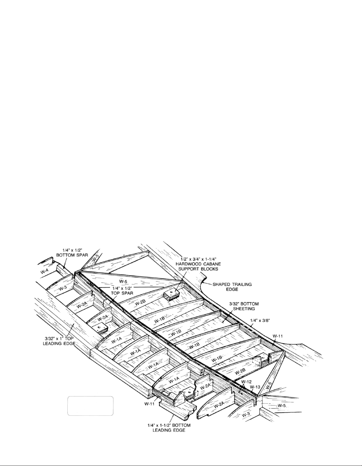
TOP WING CENTER SECTION
CAP STRIPS AND
3/32" x 1" TRAILING
EDGE NOT SHOWN
3
Page 4

6. Internally, the center section is done and all that
remains is the addition of the top 33/32"
sheeting—note grain. From the sheeting stock
provided, cut, fit and glue the sheeting in place.
When dry, remove the center section from your work
surface. Useyoursanding block tosmooth it'souter
W-1A and W-1B sides for mating to the outer wing
panels. The top, bottom and leading edge can now
also be sanded to shape. Set this assembly aside
now.
7. In this step we want to prepare each of the required
components—the top and bottom spars, the 3/8" x
1/2" front L.E. and the rear 1/4" x 3/8" T.E.—with the
proper dihedral angle at their inboard ends. The
cross-section of the wing that is shown on the plans
is ideal forthis purpose. Simply lay, for instance, the
bottom 1/4" x 1/2" balsa spar in place over this
drawing. Note that the outboard end is cut at 90
degs.; but that the inboard end must be cut at an
angle to achieve the required 3/4" per panel dihedral
angle. Make two of these bottom spars. Now repeat
this process with the top spars, the leading edges
and the trailing edges (note that the length of the
leading edges is developed from the top view of the
wing plan). The inboard edges of the
lower leading edges should be first cut at 90 degs.
and then slightly chamfered to match the needed
dihedral angle.
8. Start construction by first
lower leading edges in place, directly overthe plans.
Note that the inboard edges of these two parts
terminate at the out edges of the two outboard
W-1A's. Now pin the 3/32" x 1" bottom trailing edge
planking in place. Glue the 1/4" x 3/8" trailing edges
in place on the top, rear of the 3/32" trailing edge
bottom sheet. From your kit box locate two 28"
lengths of the tapered
on the plans that the inboard ends of the tapered
trailing edges have been scalloped to blend into the
center sections, using the plans as a guide, do this
now. Glue the tapered trailing edges in place—pin
securely. From the 3/32" x 1/4" x 36" stock provided,
cut, fit and glue each of the bottom capstrips in
place—pin to secure. Using the 3/32" sheet balsa
provided, measure, cut and glue the inboard bottom
wing sheeting in place—note grain direction.
Locate the two required W-6 wingtips, clean their
edges and glue in place. The bottom 1/4" x 1/2" spars
(angled ends inboard) are now glued in place to the
bottom wing sheet and capstrips. Now glue all
required W-2A, W-2B, W-3 and W-4 ribs in place,
making sure they are vertical to the work
surface—DO NOT glue W-3P's in place yet.
9. From your kit box locate the die-cut sheet
containing the four "light ply" W-3P wing ribs. Both
the upper and lower wings use two of these special
ribs for attachment of the interplane struts. Note
that each of these ribs have indentions on them for
location and placement of the nylon mini horns,
used for attachment of the interplane struts. On the
1-1/2"wide
pinning
the
trailing stock. Note
balsa
for
1/4" x 1-1/2"
1/4" x 1-1/2"
upper wing, the location of these horns is shown on
the lower left side of plan sheet #5. Route or cut a
slot between the two lower sets of front and rear
indentions to allow the base of the mini horn to fit.
As long as you're doing this now, go ahead and cut
the slots required for these ribs for the bottom
wing—these are the top front and rear set of
indentions. Once the ribs have been properly
slotted, place the two required for the bottom wing
back in your kit box for later assembly. The two
appropriate W-3P ribs for the top wing are ready for
installation. First, cut, fit and glue in place the 3/32" x
1/4" lengths of capstrip stock shown on the plans as
fitting directly beneath each of the mini
locations. Glue W-3P's in place.
10. Locate and remove 14 W-5 rear angled ribs from their
die-cut sheets. Note on the plans that the forward
ends of these ribs are chamfered to fit against the
W-3 rib sheets and that their placement does not
interfere with the placement of the top spar slots.
Also note that the innermost W-5 rib must be
trimmed slightly so as not to interfere with the
placement of the main dihedral brace. GlueW-5's in
place. Glue all of the wingtip braces (W-7, W-8, W-9,
W-10, and W-15) in place on the W-6 wingtips. Note
that W-7, W-9 and W-10 need to have their inboard
ends chamfered with a sanding block to fit flush to
the outer face of W-3.
11.
From your hardwood parts bag, locate the four 1/2" x
5/8"" x 1-1/2"
epoxied in place as shown on the plans, against the
inboard faces of W-2A and W-2B and to the bottom
3/32" bottom center wing sheeting—we suggest
use of a 1-3 hour-type epoxy for this step.
12. Now take the center section which was assembled
earlier and fit it to one of the wing panels. Tilt it until
the two arms of the W-11 ply dihedral braces fit flush
to the front and rear bottom sheeting and the center
brace assembly is correctly positioned against
the bottom spar. Check this fit to be sure all
components fit nicely. Trim as needed to get proper
fit. Prop and/or pin this center section in this
position as you will use it as a guide for the
remaining wing panel parts. Remember not to glue
anything to the center section yet; it's only in place
for spacing purposes.
13. Glue the front 3/8" x 1/2" leading edge in place on top
of the lower
front of each full and half rib (angled end inboard to
fit against tilted center section). Glue the top 1/4" x
1/2" spar in place (angled end inboard). Cut, fit and
glue the 3/32" x V leading and trailing edge planking
in place—pin or tape to hold. Remove the center
section from the wing panel and repeat the above
steps on the remaining panel.
14. Cut, fit and glue all top 3/32" x 1/4" capstrips in place
on all of the ribs and half ribs.
15 Remove the wing panels from the work surface.
Inspect them for any dried globs of glue, remove
cabane support blocks. These are now
1/4" x 1-1/2"
leading edge and against the
horn
the
4
Page 5

these with a #11 X-acto knife. Tape or hold the two 2.
wing panels together with the bottoms of each
facing the other—align carefully. Use your sanding
block to now shape the forward wingtips identically
with each other and the curves shown on the plans.
With the exception of the inboard ends, use your
sanding block to carefully 'match' the wing panels,
leading edges, tips and trailing edges. Separate the
panels and use a sand ing block with light paper over
all of the panel's surfaces to smooth them for later
covering.
16. Firmly pin and/or weight the center section over your
protected work surface and epoxy the left and right
wing panels in place to it, with the tips of each panel
supported off the work surface by 3/4" to impart the
correct dihedral. Do not use so much adhesive that it
drips or runs but enough to adequately coat the
parts required. Using a 1-3 hour type epoxy will give
you plenty of time to position all of the components. 3.
Allow the structure to cure.
Remove the wing from your work surface and
inspect your work. Do any touch-up sanding or filling
as needed. The upper wing is now complete with the
exception of the upper panel sheeting over the
hardwood blocks.
Using the plans as a guide; measure, cut and buttglue the
sheet and the 3/32" x 1" trailing edge that make up
the bottom of the center section. Note grain direction of these pieces. Measure, cut and glue in place
the 3/8" x 1/2" upper leading edge. Glue one of the
W-11 ply dihedral braces in place against the inside
surface of the leading edge—be sure that it's
centered. Glue the two outer W-1A's in place against
the rear face of the dihedral brace, lined-up with the
edges of the bottom sheeting at right angles to your
work surface. Now glue two W-1A's in place just in-
board of the outer ones—note "tick" marks on
plans. The two remaining W-1A's are now glued in
place, at the center of the structure, spaced 1/4"
apart to allow later dowel insertion.
As shown, the main dihedral brace system is a composite made by laminating the two W-12's (ply) to
each side of the W-13, which results in a 1/4" thick
part—do this now. Glue the completed composite
dihedral brace in place to the bottom sheeting and
up against the rear edges of the six W-1A's. Be sure
this part is centered.
1/4" x 1-1/2"
lower leading edge,
3/32"
balsa
LOWER WING ASSEMBLY
The lower wing for the Elder Biplane is almost identical in
constuction to that of the upper wing, just built. Part
numbers and wood sizes are also the same. However,
there are some differences, primarily in the center section structure and in part counts. Carefully join the plans
for the BOTTOM LEFT WING and the BOTTOM RIGHT
WING, Plan Sheets 3 and 4, at the center lines provided
and accurately secure with tape. This provides the full
wing plan on which to work. The lower wing, like the top,
will be built directly over the plans, so cover them with a
MonoKote backing or clear food wrap.
1. Start with the center section first. Locate the die-cut
sheets containing parts W-11 (2, ply), W-12 (2, ply),
W-13(1, balsa), 6W-1A's and 4W-1B's. Remove these
parts from their sheets and clean up any rough
edges
before assembly.
4. From your kit box, locate a piece of 1/4" x 1/2" spar
stock and cut two 5" lengths. Glue one of these
pieces in the top rear slots in the W-1A's and against
the top forward face of the center dihedral brace.
Glue the other on the bottom sheeting against
bottom rear face of the dihedral brace.
5. Now glue the four W-1B rear half-ribs in place behind
the main dihedral brace. Glue the remaining W-11
(ply) dihedral brace in place on the bottom sheeting
and against the rear edges of the four W-1B's. Locate
the 1/4" x 3/8" trailing edge material in your kit box
and cut a 5" length. This is now glued in place
against the rear face of the rear W-11 brace and
the bottom sheeting.
the
to
5
Page 6
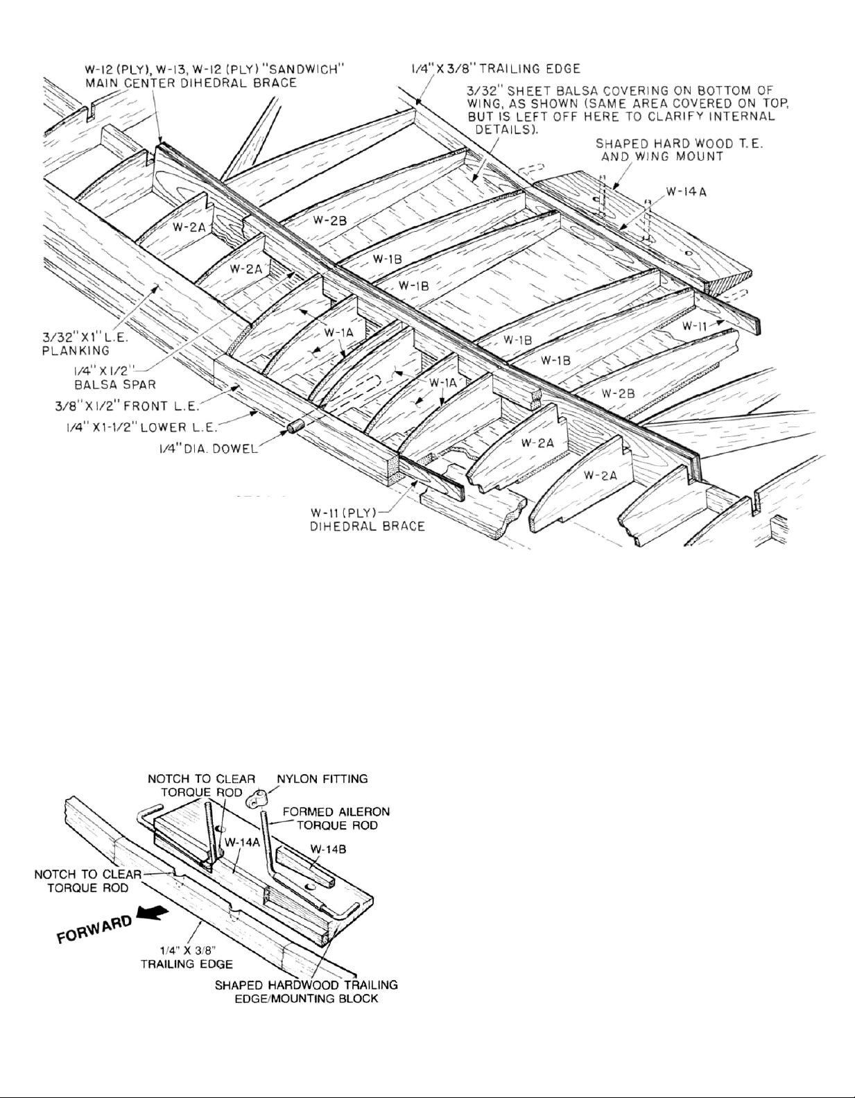
BOTTOM WING CENTER SECTION
6. In this step you are going to assemble the 5" length
of shaped hardwood trailing edge stock and the
aileron torque tubes and wires to the wing center
section. Also locate and remove from their die-cut
sheets, parts W-14 and W-14B (due to the die-cut process, you have been provided with two sets of these
parts, you will need only one set). Please refer to the
detail drawing provided to understand the relationship of these parts.
Start by glueing W-14A to the front face of the
tapered hardwood trailing edge piece. Make sure
W-14A is centered and that the bottom edge of the
part coincides with the bottom surf ace of the trail ing
edge piece. As shown, the trailing edge must be
notched a little to allow rear movement of the threaded linkage arms. Do this now with either a rat-tail file
or a Moto-Tool and router bit. Note that there is a
right and a left aileron drive assembly. Hold one of
these assemblies (it makes no difference which one)
in place to the trailing edge/W-14A assembly in it's
proper location. Apply glue to the rear face only of
one of the tapered W-14B's (tapered end outboard)
and glue it in position to the front face of the trailing
edge, thus providing a "nest" for the aileron drive
assembly. Repeat this process for the opposite side.
Remove the aileron drive assemblies and use a
sanding block to true-up each side of the trailing
edge assembly (top and bottom) and each end. Insert the two aileron drive assemblies into their appropriate "nests" and hold this entire assembly to
the trailing edge of the wing center section. Note
that you now must slightly notch the center
section's 1/4" x 3/8" trailing edge to allow forward
movement of the threaded linkage arms—do this
now. Remove the two aileron drive asemblies and
usesandpapertorough-upthesurfaceofeachofthe
assemblies' brass tubes. Mix a small amount of 1-3
hour epoxy and carefully glue only the torque rod
6
Page 7

tubes into their appropriate locations—DO NOT
GET GLUE ON THE WIRE TORQUE ROD ARMS.
Carefully wipe off any excess glue. This completed
assembly can now be carefully glued directly to the
trailing edge of the center section and allowed to
dry.
7. The center section, from about the center of W-13,
back to the trailing edge can now be sheeted with
3/32" balsa—note grain direction. At the leading edge
of the center section, cut, fit and glue in place a
piece of 3/32" x 1" leading edge sheeting. For now,
this completes the center section. You will add the
last piece of top sheeting after the forward wing
hold-down dowel is installed.
8. In this step we want to prepare each of the required
components—the top and bottom spars, the 3/8" x
1/2" front L.E. and the rear 1/4" x 3/8" T.E.—with the
proper dihedral angle at their inboard ends. The
cross-section of the wing that is shown on the plans
is ideal forthis purpose. Simply lay, for instance, the
bottom
1/4" x 1/2"
balsa spar in place
over
this
drawing. Note that the outboard end iscutat90degs.; but
that the inboard end must be cut at an angle to
achieve the required 3/4" per panel dihedral angle.
Make two of these bottom spars. Now repeat this
process with the top spars, the leading edges and
the trail ing edges (note that the length of the leading
edges is developed from the top view of the wing
plan). The inboard
edges
of
the
1/4" x 1-1/2"
lower
leading edges should be first cut at 90 degs. and
then slightly chamfered to match the needed
dihedral angle.
9.
Start
construction by first
pinning
the
1/4" x 1-1/2"
lower leading edges in place, directly overthe plans.
Note that the inboard edges of these two parts ter-
minate at the outer edges of the two outboard
W-1A's in the center section. Now pin the 3/32" x 1"
bottom trailing edge planking in place. Glue the 1/4"
x 3/8" trailing edges in place on the top, rear of the
3/32"trailing edge sheet. From the 3/32" x 1/4" x 36"
stock provided, cut, fit and glue each of the bottom
capstrips in place—pin to secure. Using the 3/32"
sheet balsa provided, measure, cut and glue the inboard bottom wing sheeting in place—note grain
direction. Locate the two remaining W-6 wingtips,
clean their edges and glue in place. The bottom 1/4"
x 1/2" spars (angled ends inboard) are now glued in
place to the bottom wing sheet and capstrips. Now
glue all required W-2A, W-2B, W-3, W-3P and W-4 ribs
in place, making sure they are vertical to the work
surface.
10.
Locate and remove the remaining twelve W-5 rear
angled ribs from their die-cut sheets. Note on the
plans that the forward ends of these ribs are
chamfered to fit against the W-3 rib sides and that
their placement does not interfere with the placement of the top spar slots. Also note that the innermost W-5 rib must be trimmed slightly so as not to interfere with the placement of the main dihedral
brace. Glue W-5's in place. Glue all of the wingtip
braces (W-7, W-8, W-9, W-10, and W-15) in place on
the W-6 wingtips. Note that W-7, W-9 and W-10 need
to have their inboard ends chamfered with a sanding
block to fit flush to the outer face of W-3.
11. Now take the center section which was asembled
earlier and fit it to one of the wing panels. Tilt it until
the two arms of the W-11 plydihedral braces fit flush
to the front and rear bottom sheeting and the center
brace assembly is correctly positioned against the
bottom spar. Check this fit to be sure all components fit nicely. Trim if needed to get proper fit.
Prop and/or pin this center section in this position as
you will use it as a guide for the remaining wing
panel parts. Remember not to glue anything to the
center section yet; it's only in place for spacing pur-
poses.
12. Glue the front 3/8" x 1/2"" leading edge in place on top
of the lower
front of each full and half rib (angled end inboard
1/4" x 1-1/2"
leading edge and against
the
to
fit against tilted center section). Glue the top 1/4" x
1/2" spar in place (angled end inboard). Cut, fit and
glue the 3/32" x 1 "leading and trailing edge planking
in place—pin or tape to hold. Remove the center
section from the wing panel and repeat the above
steps on the remaining panel.
13. Cut, fit and glue all top 3/32" x 1/4" capstrips in place
on all of the ribs and half ribs.
14. Remove the wing panels from the work surface. Inspect them for any dried globs of glue, remove these
with a #11 X-acto knife. Tape or hold the two wing
panels together with the bottoms of each facing the
other—align carefully. Use your sanding block to
now shape the forward wingtips identically with
each other and the curves shown on the plans. With
the exception of the inboard ends, use your sanding
block to carefully "match" the wing panels, leading
edges, tips and trailing edges. Separate the panels
and use a sanding block with light paper over all of
the panel's surfaces to smooth them for later covering, after final assembly. The three lower wing components are now complete and should be set aside
for later assembly.
TAIL GROUP
The tail group of yourEIder Biplane is built directly over the
plans in a quite straight-forward manner. Note there are
options open to you with these parts in terms of shape.
The stab's gentle curves which terminate in sharp
points at the trailing edge of the elevators give a certain
"look," which can be changed by rounding the outboard
trail ing edges of the elevators. This "softens" the look of
these shapes. The same thing can be done to the fin and
rudder, top and bottom—looks nice. As shown, you can
also scallop the trailing edges of the rudder
and
elevators to give yet another different look.
1 . Start with the stab. Build directly over the plans
which have been covered with the clear backing
from MonoKote or food wrap. Position the two S-1
7
Page 8

tips in place and the center S-2 as well; pin. From the
1/4" x 1/2" balsa stock provided, cut, fit and glue in
place the two leading edges and the trailing edge.
Using the same material, cut and glue in place the
"cap" in front of S-2, thus completing the stab
outline.
2 . Cut,fitcarefullyandgluethe 1/4 "sq.balsaribs(three
per side) in place. Use short lengths of 1/4" x 1/2"
stock to make the fillets—note grain direction.
3 . From
4 . Remove the stab and elevators from the plans. Build
5. Using the 3/32" x 1/4" balsa provided, cap strip both
6 . The elevators, stab, fin and rudder are now final-
the
1/4 " x
2-3/4"
balsa stock provided, measure
and cut the two elevators. Notch them as shown to
accept the 1/4 " dia. dowel elevator joiner. With the
stab still in position on the work surface, pin the
elevator halves in place. Protect the trailing edge of
the stab with a strip of waxed paper and epoxy the
dowel joiner in place in the notches—allow to set
completely.
the fin next in the same manner using the R-1 and R-2
die-cut pieces with 1/4" sq. and 1/4" x 1/2" balsa
frames shown. Cut the rudder to shape from the remainder of the
elevators. Position the rudder in place to the back of
the fin and glue R-3 in place to the leading edge of
the rudder. Remove the parts from your building
board.
sides of the fin and stab assemblies as shown on the
plans. Be sure, when capping the lower edge of the
fin, to leave a distance of 3/32" from the bottom to
allow the fin to fit into the slot between the two top
S-3 caps. Glue the two S-3 caps to the upper surface
of S-2, leaving a 1/4" gap at the centerline for the fin.
Test-fit the fin in place on top of the stab. With the fin
still in place, cut, fit and glue the forward 3/32" x 1/4"
cap strip in place forward of the fin. Remove the fin.
sanded to shape. Start by using masking tape to
mount the elevators to the stab. Use a sanding block
to go over all of the outside surfaces to carefully
match them. Lay the stab on a flat working surface,
masking tape down, and use the sanding block to
sand it flat. Use the sanding block to taper the
elevators as shown on one side. Tape the
stab/elevator hinge line, turn the stab over, remove
the tape from this side, and repeat the process. The
same method is used for the fin and rudder. Once
complete, use sandpaper to round the leading
edges. Set these parts aside for covering and
assembly to the fuselage.
1/4" x 2-3/4"
balsa stock used for the
fuselage can only be ruined in one way; building it crook-
ed. This can be done by not making the fuselage side
frames identical and/or mis-sizing the top and bottom
cross braces. Another common error is to make im-
proper joints. The Elder Biplane relies a great deal on the
strength of its frame—take the time to make each and
every joint required, fit as precisely as possible. Also
note that the uprights and cross braces are a mix of both
spruce and balsa. These are notated.
Join Plan Sheets 1 and 2 at the center lines provided. As
shown, lay your straight edge along the top longeron to
line-up the two drawings. Carefully tape the plans
together. Now cut-out the Top View section and again
using your straight edge, placed along the center line of
both drawings, carefully tape in place. Since the side
frames will be built directly over the plans, cover and protect them with either MonoKote backing or clear food
wrap.
1. Locate and remove both F-5 die-cut fuselage
doublers from their sheet. Pin or hold these parts
together, aligning carefully, and use your sanding
block to "match" their outer edges exactly. Pin one
of the F-5's directly over it's location on the plan.
Measure, cut and pin in place the upper 1/4" x 1/2"
balsa sub-longeron which fits between the F-6 and
F-11 locations and directly beneath the top spruce
longeron.
2. Note that the top 1/4"sq. spruce longeron is actually
three separate lengths. There are two required gaps
of 5/8" each to fit the slotted cabane trunnion blocks.
Carefully cut these three lengths of spruce and glue
them in place, overthe plan, to the top surface of the
1/4" x 1/2" sub-longeron. Use crossed pins to accurately secure the rear end of this longeron to your
work surface. Measure, cut and glue the bottom 1/4"
sq. spruce longeron in place to the bottom of F-5
(note the angled cut at the bottom, front end of this
longeron to accomodate the wing saddle). Again
secure the rear end of this longeron to your work sur-
face with crossed pins.
3. Cut, fit and glue in place the six (6) 1/4" x 1/2" balsa
uprights, shown from A-A through C-C.
4. With the top and bottom spruce longerons securely
and accurately positioned overthe plans, cut, fitand
glue in place the six (6) 1/4"sq. spruce uprights, starting at the rearmost tailpost and working forward.
This completes the first fuselage side frame.
Remove it from yourwork surface and use a sanding
block to lightly sand each side of it smooth.
FUSELAGE ASSEMBLY
Before starting construction, study the plans, cross sections and illustrations to familiarize yourself with how
the fuselage is assembled. Note that it really is nothing
more than a basic "box" fuselage with semi-formers on
the top and in the nose area to create the required rounded look. This simple and effective way of making a
5. Reposition the frame onto your work surface and, as
shown, cover it with protective backing from
MonoKote or food wrap. The second, identical
fuselage frame is now built directly over the bottom
one. Again, take your time and carefully build this
second frame exactly like its mate.
8
Page 9

Remove the two completed frames from your work
surface and again use your sanding block to lightly
sand both sides of the newly completed frame. Pin
and tape the two frames together and use your sanding block to make sure they are identical. From
your kit box locate the three 1/4" x
blocks,
ting
cabane trunnion blocks. Use sandpaperto rough-up
the two lengths of brass tubing and epoxy them into
the slots of the cabane trunnion blocks, being sure
to center them. Use at least 1-hour-type epoxy for
this job.
Carefully position the two fuselage frames, upside
down, over the top view of the plans. Block and/or pin
as needed to hold them in place at right angles to
your work surface. Take two of the
ply blocks and epoxy them in place in the cut-outs
provided at the forward end of F-5. Epoxy the third
1/4" x 1" x 3-5/8"
F-5, in the wing saddle. From the hardwood parts
bag locate the
ends of this part to fit nicely between the F-5's, at the
very leading edge. Epoxy F-7 in place. Allow the
epoxy to cure before removing structure from your
work surface.
With the structure upright, epoxy the two cabane
trunnion blocks, tubes already installed, in place in
the gaps provided in the top spruce longerons. Use a
slower curing epoxy (1-3 hour type) to give you the
time to ensure that the structure, thus far, is truly
the
tubes
two
1/8"
I.
D. x 3-3/4"
and the two slotted
ply block into the slots at the rear of
1/8" x 1" x 3-1/8"
1" x
3-5/8" plywood
brass carbane moun-
1/4" x 5/8" x 3-5/8"
1/4" x 1" x 3-5/8"
ply
F-7.
Touch-up
the
square. While waiting for the glue to cure, measure
and cut the six required identical lengths of 1/4" x
1/2" balsa top and bottom cross braces and the three
also identical lengths of 1/4" sq. spruce top and bottom cross braces. Again, all nine of these cross
braces are of identical length to fit exactly between
the fuselage frames. Starting at the top front of the
fuselage, glue all five of the top 1/4" x 1/2" cross
braces in place, back to and including Section C-C
(the plans show 1/4" sq. material at this point,
disregard and install the 1/4" x 1/2" brace). Behind
Section C-C, at the location of the first vertical 1/4"
spruce upright, glue one of the 1/4" sq. spruce cross
braces in place. Turn the fuselage over and glue the
remaining 1/4" x 1/2" cross brace in place at Section
B-B and the remaining two 1/4" sq. spruce cross
braces at Section C-C and at the location of the first
vertical upright. Useyoursanding block to lightly go
over all four sides of this structure.
9. While we still have relatively good access to the inside of the fuselage, now is the time to drill the re-
quired 1/4" dia. hole through F-7 and into the /owe/wing's center section. Accurately pin and/or tape
the center section into the wing saddle. Use a 1/4"
drill bit and electric drill to drill a hole through F-7,
the leading edge and the forward W-11 dihedral
brace. Remove the center section and set it aside for
now.
10.
From your kit box, locate the
firewall, the four 4-40 blind mounting nuts and the
four 4-40 x 7/8" R.H. bolts. You will also need the
1/4" x 3-3/8" x 3-3/4"
ply
9
Page 10

molded fiber-filled motor mount. Using the plans
and the motor mount, you must now carefully mark
the
location of the four mounting holes required for
the
mount. Using a drill and a 1/8"dia. bit, drill the four
holes through the firewall. Now epoxy the 4-40 blind
mounting nuts in place to the back of the firewall, into the holes just drilled—keeping adhesive out of
the threads. Locate the motor mount to the front of
the firewall and use the bolts to tighten it in place.
Allow the glue to cure and remove the mount. The
firewall is now epoxied in place to the front of the
fuselage—align carefully and allow to cure.
11.
Assemble the fuel tank that you plan to use. This
design can use either 10 or 12 oz. fuel tanks. (We've
shown a Du-Bro 12 oz. tank, mounted upright, on the
plans.) Fit your tank into the nose of the fuselage
assembly. You can see that the tank needs to be supported to sit level. Make up a couple of supports for
the tank (two lengths of 1/4" x 1/2" balsa, between
the
two F-5's works well) and glue them in place,
making sure the tank now rests level. In this way,
when the fuselage is complete, the tank can be inserted from the lower wing opening into the nose
and removed, if needed, with assurance that it is in
place correctly. Now use a 3/16" dia. drill bit to make
the two required holes through the firewall for the
fuel tubing (we like and suggest a "two line system";
one fuel line for fuel feed and filling and the other for
the pressure tap and overflow). Remove the tank.
12.
Drill and tap the holes necessary in the motor mount
to attach your engine (we like to use 4-40 Allen-head
hardware for this purpose). Attach the motor mount
to the firewall and the engine to the mount. By view-
ing from the front, determine the location of the
throttle tube housing exit hole. This should be linedup with the carb's throttle arm. Drill a 1/16" dia. hole
throughthefirewallforthistube.Rough-uptheouter
surface of the outerthrottle tube housing and glue it
in place in the firewall—about 3/16" of it should protrude out from the face of the firewall, the rest of it
runs into the radio
still fits in place.
13. The servos shown on the plans are of average or
standard configuration; yours may be different
(taller, wider, etc.). The Elder Biplane will accept
almost any radio system. In this step you are going
to determine the location of the 1/4" x 1/2" balsa
servo tray bearers. Remember that the servo tray is
1/8" thick ply. Lay one of the servos that you plan to
use directly over the side of the fuselage, at the loca-
tion shown on the plans and mark the location of
these tray bearers. Cut, fit and glue in place the servo
tray bearers, one on each side of the fuselage.
14. Using the 1/8" x 3" x 30" balsa sheet provided, the
bottom nose of the fuselage, back to the rear face of
F-7 is sheeted—note cross grain direction, typical
throughout this step. Again, hold or tape the lower
wing's center section in place in the F-5 wing saddle.
The bottom rear of the fuselage is now sheeted from
the
trailing edge of the center section, back to the
compartment. Be
sure your
tank
point shown on the plans. The top of the fuselage is
now sheeted, as shown on the plans and illustrations. As shown, do not sheet the top of the 1/4" ply
firewall, this is the location of the top F-3 former. Use
your sanding block to smooth the fuselage sides
and sheeting just applied and to blend the bottom
nose sheeting and landing gear mounting blocks to
the smooth curve shown on the plans.
15. Using a pencil and triangle, hold the fuselage directly over the side view on the plans and mark the loca-
tion of formers F-6, F-8, F-9, F-11 and F-12 directly onto the top 1/8" balsa sheeting. From your kit box,
locate the two 1/8" x 6" x 21" balsa sheets that are
the fuselage sides. Use a straight edge and an
X-acto knife to true-up one of the long edges of each
of these sheets. Now lay one of the sheets directly
over the fuselage, aligning its trued-up edge with the
top surface of the top 1/8" sheeting. Note that the forward end of the sheeting terminates at section B-B.
With the side sheeting properly aligned, press it to
the fuselage side at the tube ends of each of the
cabane trunnion block locations. This should indent
the sheeting with the slightly protruding tubing
ends. Remove the sheeting and use a 1/8" dia. drill bit
to make a hole through the sheeting at both indentations. Reposition the sheeting to the fuselage and
use a pencil to carefully draw the bottom and rear
fuselage side outlines onto the sheeting. Use your
X-acto knife to remove the drawn outline. This
fuselage side is now glued in place to the fuselage
frame. Repeat process for the opposite side. Use
your sanding block to true-up all edges and sides.
16.
Locate and remove 1/4" die-cut parts F-3 (1) and F-4
(2). Stand the fuselage on its nose, firewall flat to
your work surface. Glue the two F-4 formers in place
to each side of the firewall and the F-3 former to the
top of the firewall and the tops of the two F-4's. Use
your sand ing block to smooth the formers to the face
of the firewall. Locate and remove formers F-6, F-8,
F-9, F-11 and F-12 from their die-cut sheets. Using
the location marks made earlier, glue each of these
semi-formers in place to the top of the fuselage.
Make sure they are centered and that they sit at right
angles to the fuselage sheeting. (Note that there will
be one extra F-6 former—it will not be needed.) From
the stockwood in your kit box, locate a length of 1/4"
sq. balsa. Measure, cut and fit the required length to
fit into F-12 (at the rear), forward to and including the
F-2 location—4-1/2" ahead of section A-A. Partially
cut through and crack this longeron at the F-9 and
F-6 former locations to obtain the right outline. Glue
this longeron in place. Cut and fit the two required
1/4" sq. balsa stiffeners that fit into the F-4 formers
and angle back to the second 1/4" x 1/2" upright (section B-B). Note thatthese two pieces fitonlyintoone
half of the width of F-4 and that they are notched to
fit inside of the upright (see Top View).
10
Page 11

17.
You are now going to sheet the top turtle deck back
from F-6 to the rear of the fuselage with the 1/8" x 3"
x 30" balsa sheet provided. We suggest that you
break this up into four areas; a left and a right from
F-6 to F-9 and a left and a right from F-9 to the back of
the fuselage. We also suggest starting at the center
of the top longeron and working down. Wetting the
wood with either water or a little ammonia will make
the curves required quite easy. Also be sure to leave
yourself a little "shelf" at the F-6 former for the forward sheeting and at the F-9 former for the rear
sheeting. Take your time, trim and sand the sheeting
for a good fit before glueing in place. A thick type CA
glue is good here as it eliminates the need for pins.
18.
Cut, fit and glue in place the two side cow/longerons
which fit into the half-notches left in the F-4's and extend out to the F-2 location. (See illustrations and
Top and Side view of the plans.) Locate and remove
formers F-1 and F-2 from their die-cut sheet. Observe
how F-2 sits in place when attached to the three 1/4"
sq. pieces extending out from the cowl. Viewed from
the side and top, F-2 is parallel with the firewall. Use
a ruler to be sure and trim the ends of the 1/4" sq.
material as needed. Once satisfied, glue F-2 in
place. Use your sanding block to lightly sand the forward face of F-2 smooth. Position F-1 in place
against F-2. Note that doing this creates an approximate "shelf" of 1/8". This is to locate and glue the forward cowl sheeting in place. Glue F-1 to F-2. Last,
glue the two required 1/4" sq. balsa pieces that fit
from the bottom, outside corners of F-2 down to the
bottom, outside corners of the F-4's. Bevel-cut each
end of these to fit correctly.
19. Note the illustration in the lower left-hand corner of
Plan Sheet 1. This gives the correct sequence for
finish-sheeting the fuselage top and cowl. Again,
wetting the various balsa sheeting pieces with water
or a little ammonia helps the material to readily conform. Take your time to achieve accurate, gap-free
fits before glueing these pieces in place. Thick CA
11
Page 12

adhesive works very well here, eliminating the need
for pins. If you've taken your time and fitted these
pieces in place with a minimum of gaps, all that remains is sanding to shape.
20.
Use your sanding block and coarse paper to now
bevel the inside ends of the spruce fuselage
framework at the tailpost—see Top View of plans.
Once satisfied, careful ly epoxy these ends together,
providing equal bends to each side of the fuselage
when viewed from the top. Also view the structure
from the rear making sure everything is square.
When satisfied, clamp securely and allow to cure.
Accurately cut five (5) pairs of top and bottom 1/4" sq.
spruce cross braces which will correspond, in location, to the exposed uprights. We suggest cutting
these pieces at the same time, taking care to ensure
that they are of equal length. With the tailpost joint
fully cured, glue cross braces in place, working from
the front to the back. Check each cross brace installation as you go, making sure the structure stays
square.
21. The complete fuselage, including the exposed
spruce framework should now be given a complete
sanding. Any gaps, nicks or dings should be filled
and sanded-off. Remove the two F-10 (ply) pushrod
guides from their die-cut sheets. Use your sanding
block to clean-up their edges and the slot. Once
satisfied, glue F-10's in place to the outside of the
vertical uprights, beneath the stabilizer location.
The last thing to do is to make the cut-outs for the
cockpit locations for your "pilots". At this point, you
can choose to make the model a one or two "holer."
With the exception of the cabane struts and some
other details which will follow, your fuselage is complete.
WIRE PARTS ASSEMBLY
I. LANDING GEAR
The pre-bent front and rear 1/8" dia. M.W. landing gear
(L/G) forms must be joined together at the bottom,
towards the wheels. We recommend soft copper wire for
firmly and neatly wrapping the two pieces together prior
to soldering. We would highly recommend the use of
HARRIS'S STAY-CLEAN FLUX and their silver solder for
this operation. Although a soldering iron will work, with
patience, these joints can be quickly and permanently
made with the use of a small hobby-type gas torch.
1 . Locate the position of the rear "cross-axle" wire to
the bottom rear ply L/G plate on the fuselage bottom.
While holding the wire in place, slip the two formed
metal clips onto the wire. Use a pencil to mark the
hole locations of these clips onto the ply base, then
remove the wire and clips. Drill shallow, smalldiameter "guide holes" for the clip's #2 x 3/8"
screws. Now attach the landing gear wire to the
fuselage with the clips and screws— do not overtighten. Repeat this process with the forward landing gear wire.
2 . Pull the two wire parts togetheruntiltheytouch.The
two short bent 'arms' on the forward leg should lineup with the legs of the rear L/G wire. If needed, use
pliers to adjust these arms until they fit neatly and
uniformly.
3 . Use soft copper wire to now neatly wrap the forward
short arms to the rear L/G wire as shown in the illustration in the plans. Apply some STAY-CLEAN
flux to the joint and solder. Repeat the process on
the opposite side. Be neat and try to be sure that the
joint is sol id without a lot of excess solder. Once the
joint has been made, clean with water to remove all
flux and dry-off with a paper towel.
4 . As shown, the crossed-axle landing gear system
derives its ability to accept landing loads and shock
from the two independent axle legs. These need to
be joined at two
This distance has shown very good shock-absorbing
abilityforEIderBiplanesweighing 7-1/2
these axles
quired, wrapping with soft wire (about 1/2") and
soldering. Again, clean the solder joints completely
with water and dry.
points,
by
first measuring the
each
2-1/2"
in from the wheels.
to8-1/2
2-1/2"
distance
Ibs.Join
re-
12
Page 13

5 . The wheels can be retained in one of two ways. As
shown, simply soldering 1/8" I.D. washers in place
will do the job. A more realistic method is to fit the
axle legs with lengths of 1/8" I.D. brass tubing,
soldered in place. With the axle holes of the wheels
drilled out to fit over these pieces of tubing, the
wheels are slipped in place. Next, slip a washer over
the tubing, against the wheel. Now drill a small
diameter hole through the end of the brass tubing
and insert a small cotter pin to retain wheel. Note
that the length of the M.W. L/G axle should be
shortened first, using a carbide cut-off wheel on your
Moto-Tool.
II.REARTAILSKID
1 . From your kit box, locate the 1/16" dia. x 22" length of
M.W. and the 1/16" pre-bent skid support wire. Note the
side and bottom view of this assembly, shown on
Plan Sheet 2. Use the pattern to now bend the 22"
length of M.W. to shape—easily done with pliers.
Neatly wrap the rear tip of the skid with soft copper
wire, apply flux and solder.
2 . Now tape the main skid wire assembly in place to the
bottom rear of the fuselage, at the cross brace, just
behind D-D. Use tape to now locate the pre-bent skid
support to the bottom, rear fuselage location shown.
Use soft copper wire to neatly wrap the support wire
to the tailskid, apply flux and solder. Remove the
completed tailskid assembly from the fuselage. This
assembly should be attached to the fuselage just
prior to painting or staining the exposed spruce
fuselage longerons, cross braces and uprights. We
have used and suggest black carpet thread or fishing
line for attachment.
3 . Should you wish to make this skid steerable, we've
provided an illustration of how we did it. This
assembly is essentially the same as the nonsteerable one just made, except that the rear part of
the skid is separate and is sleeved in a 1/16" I.D. length
of brass tubing. An arm is bent, at right angles, at the
top and another length of 1/16" I.D. tubing is soldered in
place. The end of this piece of tubing is flattened and
drilled with a hole to accept a nylon clevis. Now the
rear part of the skid becomes steerable when a second threaded pushrod and nylon clevis are attached
to the rudder pushrod. Note that the parts for this option are not supplied with your kit.
STEERABLE TAIL SKID
(OPTIONAL)
13
Page 14

III. INTERPLANE STRUTS
1 . YourElderBiplanerequirestheuseoftwointerplane
strut assemblies. The pattern for their assembly and
the illustration showing the method of connection
are on Plan Sheet 4, lower right-hand corner. Note
that when complete, the two required strut
assemblies will be "mirror-images" of one another,
in other words a left and a right. The "Z-bends" on
the bottom of the strut assemblies are first fitted into the holes in the mini-horns, from the outboard
ends of the bottom wing and then rotated upwards.
The top ends, with the threaded clevises, are then at-
tached tothe mini-horns protruding from the bottom
of the top wing. Since threaded clevises are used,
the length of these struts are fully adjustable for
each side of the wings.
2 . From your kit box, locate four of the .072 dia. x 12"
threaded one-end pushrod wires and the single
piece of 1/16" x 14" M.W. These are the parts required
for the two interplane struts. From the 14" piece of
M.W., cut two 7" lengths. Use a pair of pliers to bend
the ends of each of these two pieces to the shape
shown on the plans, which connects the two threaded one-end strut wires. Wrap each end with soft cop-
per wire and solder. Cut the length of each strut as
shown on the plans and use pliers to make the
Z-bends at the bottom of each.
Later, when the model is assembled, you'll be adding the
nylon clevises to each of the strut ends and attaching
these assemblies for adjustment.
IV. FUSELAGE CABANE STRUTS
1 . From your kit box locate the four pre-bent cabane
struts and the two pre-bent cabane strut braces.
Note on the side and top views of the fuselage plans
that the four cabane struts are meant to be inserted
into the 1/8" I.D. brass tubes that have been built into
the fuselage. Note that it may be necessary to adjust
the length of these wires, at the end that inserts into
the
tubes.
and right wires to be fully inserted. Any excess
length should be removed with a carbide cut-off
wheel and your Moto-Tool. Trial-fit each of the four
pieces in place into the fuselage to be sure they insert all the way.
2 . Carefullycleaneachofthewireswithabitofthinner
to remove any oil or grease.
3 . Insert one of the cabane struts into one of the
fuselage's forward cabane tubes. Use tape to secure
it in place, at right angles to the fuselage, as shown
in the side view. Insert another cabane strut in the
rear tube location, on the same side, again using
tape to secure it vertically to the side view of the
fuselage. Now hold one of the braces in place to
these two parts, as shown on the plans. The fit and
relationship should be what is shown. Once
satisfied, carefully and neatly wrap the top, forward
leg of the brace to the top, forward end of the front
strut (a bit of tape can be used to hold the bottom,
This length
should
be
1-3/4"
to
allow
the left
rear end of the brace in place, while you're working)
with soft copper wire. Apply a little flux and carefully
solder this joint.
Now carefully slide the assembly out of the tubes
about 1". Remove the tape from the bottom rear
brace/strut joint. Wrap this joint with copper wire
and solder.
Duplicate this procedure on the other side of the
fuselage, being careful to make an exact opposite of
the first strut/brace assembly. These two strut
assemblies can now be set aside for later installation.
FINAL ASSEMBLY
1. Locate one of the 1/4" dia. x 36" spruce dowels provided in your kit. Cut a 3" length. Mix a little 1-hour
type epoxy and place some of this glue into the slot
created bythetwoW-1A's in the lower wing's center
section. Insert the dowel, through the leading edge,
leaving 1/4 " exposed. Add more glue to the top of the
now-inserted dowel. Carefully install the centersection in place to the fuselage, engaging the dowel
into the hole in F-7. Center the structure to the
fuselage and tape in place and allow to cure.
2. From your kit, locate four nylon mini-horns and
#2 x 3/8" R.H.W.S. screws. These horns are now
screwed in place to the W-3P ribs in the two lower
wing panels. It is easiest to do this if you first drill a
3/32" dia. hole through each of the horns and
screw them in place—do not overtighten.
3. Remove the center section from the fuselage once
the glue has cured. From the 3/32" sheet balsa stock,
finish sheeting the rest of the center section's top
surface. Use your sanding block to smooth this top
surface and to smooth the edges flush with the outer
W-1A's and B's.
4. Firmly pin and/or weight the center section over your
protected work surface and epoxy the left and right
lower wing panels in place to it. Do not use so much
adhesive that it drips or runs but enough to adequately coat the parts required. Prop each wingtip
up
11/16"
to achieve the correct dihedral and allow the
structure to cure.
5. When the wing can be removed from your work surface, reposition it in place in the fuselage wing saddle. Turn the whole thing over and mark the location
of the two required rear wing bolt holes onto the
wing's hardwood trailing edge. With the wing firmly
and squarely pinned and/or weighted on the
fuselage, drill two 1/8" dia. holes through the bolt
positions just marked. These two holes go all the
way through the hardwood trailing edge and the ply
wing mounting plate in the fuselage. Remove the
wing from the fuselage. Now tap the two holes in the
fuselage mounting plate with an 8-32 tap. Once the
threads have been established, use a little thin CA
adhesive to coat them and then run the tap through
these threads again, several times; this toughens-up
the threads. Now try the 8-32 nylon bolts supplied in
four
then
14
Page 15

the now-tapped holes. They should work smoothly,
without binding. Now use a 3/16" dia. bit and your
power drill to open up the two holes in the trailing
edge of the lower wing. This allows clearence for the
two nylon wing hold-down bolts. Use a razor blade to
trim the length of these bolts to 3/4".
6. From your kit box, locate the two remaining lengths
of tapered trailing edge/aileron stock. Note on the
cross section, shown at the lower left corner of Plan
Sheet 3, that the right and left ailerons need to be
beveled, top and bottom of the hinge line, to
facilitate up and down movement. First carefullycut
the ailerons to length, with about 1/32" clearence between the hardwood end of the center section and
the aileron at the W-15 location. Use a small hobby
plane and sanding block to bevel the leading edges
of each aileron, as shown. Next, locate, mark and
drill the 1/8" dia. hole in the inboard leading edge of
each aileron that will engage the exposed torque rod
ends. From the parts bag, locate the two 1/8" O.D. x
7/8" brass tubes. Rough-up their outer surfaces and
insert them into these holes to a depth of about 1".
Now use your MotoTool or X-acto knife to make a
groove from these holes, inboard to the ends of the
ailerons. These grooves will hold the torque rod
arms and allow the ailerons to fit up to the wing's
trailing edges. Test fit each aileron forcorrect fit and
make any necessary adjustments.
7. Use a soft pencil to mark the location of each of the
five (per side) aileron/wing hinges. Use a #11 X-acto
blade to carefully and accurately slot the wing and
its corresponding aileron for the nylon hinges.
NOTE: The hinge line must line up with the torque
rod arm for free, non-binding movement.
8. Temporarily mount the ailerons in place, hinged, to
the lower wing. Sand the entire structure to final
shape. Remove the ailerons and hinges and set them
aside for final attachment after covering.
9. Using the plans and a soft pencil, carefully mark the
positions of each of the four required 1/8" holes on
the bottom sheeting of the top wing. These holes are
required to engage and mount the top wing to the
cabane strut assemblies.
Now bolt the lower wing to the fuselage and slip the
left and right cabane strutwire assemblies intotheir
tubes—use tape to retain these temporarily. Gently
place the top wing onto the top of the cabane stubs,
centering it as close as possible to the four pencil
marks just made. The pencil marks may not line-up
exactly, just do your best to get the stubs and marks
as close as possible to one another.
Once the wing is in this position, you have some
observations to make. First, when viewed from the
top, the leading edges of both upperand lowerwings
should be parallel. If not, shift the top wing slightly
to achieve this condition. Next, view the model from
the front to determine that the top wing is centered
(disregard any wing low condition for now) and adjust as needed to achieve this condition.
The last observation to make is the relationship
the tops of the wire cabane stubs to the 1/2" x 5/8'' x
1-1/2"
be sure that the hole locations will be approximately
those shown on the plans and cross sections. If
some bending adjustments in one or more of the
cabane strut arms needs to be made, now is the
time.
Once all of the fore-going criteria has been met,
uniformly press the top wing to the wire stub ends
with the palm of your hand, to impress their locations into the balsa sheeting. Remove the upper
wing, turn it over and use your power drill and a 1/8"
dia. bit to drill the four holes through the bottom of
the wing panels and each of the blocks, at right
angles. Re-fit the wing in place to the cabane struts.
Use the drill and 1/8" bit to make adjustments needed
to allow the wing to accept the stubs. Take another
look at the airframe to make sure everything is sitting squarely. Once you're satisfied, remove the top
wing and remove the lower wing from the fuselage.
10. Lay the top wing upside down on your work surface
and then mount the fuselage and cabane struts into
the just-drilled holes. Locate the four required retaining straps and eight #2 x 3/8" wood screws. As
shown on the plans, the balsa sheeting immediately
beneath these straps and screws must be removed.
Do this now with a #11 X-acto knife. Using the straps
as a guide, mark the location of each of the screw
holes. Drill eight 1/16" dia. "guide holes" for the
screws. Use a screwdriver to now mount each of the
four straps in place—don't over-tighten.
With this hardware in its location established, the
top wing can now be removed from the cabane
struts. The rest of the 3/32" balsa sheeting can be fitted and glued in place on the top, over the hardwood
blocks. The wing should now be final-sanded
preparatory to covering. Finally, using the instructions in FINAL ASSEMBLY step #2, mount the four
nylon mini-horns in place to the W-3P ribs, making
sure the ends of these protrude downwards, toward
the bottom wing location—see cross section at bottom left of Plan Sheet 5.
11. A 1/16" x 1/2" x 12" ply strip is provided for the
fuselage frame "corner caps". These are shown on
the top and bottom views of the fuselage and are cut
to fit over each exposed spruce framework joint. The
pattern drawing for these parts appears at the far
right-hand side of Plan Sheet 2. Use the pattern and a
pair of shears to make these caps. These are now
carefully glued in place as shown. Use light sandpaper to smooth, prior to painting.
12.
Using the locations shown on the plans, make the re-
quired hinge slots in the stabilizer and elevatorwith
your #11 X-acto knife. Temporarily install the
elevators in place to the stabilizer with a couple of
hinges. Now make the two required hinge slots in
the fin and rudder. As the plans show, a semicircular opening, at the lower leading edge of the
hardwood blocks, just above them. You want
of
to
15
Page 16

rudder now needs to be made to allow clearence of
the dowel elevator joiner and full movement of the
rudder. With the rudder temporarily hinged to the fin,
test-fit the fin into the stab slot to be sure there is no
interference in the movement of the rudder and
elevator dowel. Disassemble these parts.
As
shown on the plans, we have used short lengths
of scrap innerthrottlepushrod stock tubing to make
the stab and fin flying wire brace points. These
should be now glued in place in pre-drilled holes.
OPTIONAL DECORATION DETAIL1/4" LENGTHS OF 3/32" OR 1/8" DIA. PLASTIC
TUBING CAN BE EPOXIED INTO EACH JOINT
BETWEEN A SPRUCE CROSS BRACE AND
UPRIGHT (16 PLACES). LATER,"RIGGING" IS
THREADED THROUGH EACH TUBE, DRAWN
TIGHT AND EPOXIED IN PLACE.
Although we have been instructing you to sand the
various components of your Elder Biplane as you were
constructing them, take the time now to carefully recheck any structure which may require final touch-up
sanding or filling. The difference between a good covering job and a great one tends to be about $2.00 worth of
sandpaper and the willingness to use it.
COVERING & FINISH
Now that all of the various components of your Elder
Biplane are completely assembled and sanded to their
final shapes, you can turn your attention to covering.
This is the point that can separate your model from
anyone else's. You must decide what you want the
finished airplane to look like. We have finished our prototypes in a wide variety of color schemes representing
everything from an R.A.F. WWI fighter (in cream
MonoKote with red, white and blue Roundels and tail
treatment) or a German WWI fighter (all red Monokote
with black Iron Cross's on a white background) to
civilian-type versions (dove gray fuselages, transparent
blue wings and tail-group and chrome Monokote
'cowls')! Interestingly, no matter what color scheme we
used, there was always a group of people at the flying
site who would stand there looking at the Elder, arguing
about what a real, full-scale aircraft it represented. Just
remember that the Elder is not a scale-model, you're free
to cover it in any configuration that stikes your fancy— it
will look great!
Before covering, it is suggested that the final finish be
applied to the open spruce fuselage structure. This can
be done is several ways. There is a very good product on
the market called Varathane that is sold through most
well-stocked hardware and lumber supply oulets. This
material is essentailly clear and will leave the spruce
about its same color, maybe a little darker, and
somewhat shiny. It is resistent to spent fuel and quite
durable in actual use. Epoxy paint, mixed to achieve a
woodish brown color and brushed or sprayed, also
works well. Take your time here, use light sandpaper to
go over the framework, smooth ing it for the finish of your
choice. When applying the finish, be sure that all of the
exposed wood, except the top, rear stab glueing area,
receives paint. We then used flat black paint (again,
epoxy is great) to paint each of the ply 'joint caps'. This
really makes the structure come to life!
Now for the covering itself. Use the directions that are
supplied with each roll of Monokote and cover each of
the various components separately; fuselage, wings,
stab, elevators, fin and rudder. Some of you might have a
problem with the wingtips of the Elder, if this is your first
venture into the use of Monokote or your first R/C
airplane. Here's a method that works quite well, First,
cover the wing panels totally, starting with the bottoms
first, including the wingtips. Then cover the tops of the
wing panels out to and including the last outboard W-3
wing rib, but not the wingtips themselves. Next, cut an
elongated triangular piece on Monokote to fit over the
space between the forward W-3 rib and the forward W-7
wingtip former—keep edges straight, allow about 1/8"
overlap and iron this piece in place. Move now to the
next exposed triangular area between W-7 and W-8 and
repeat the process. This method will provide a much
easier covering situation for the newcomer and, if done
carefully, gives you a nice looking, wrinkle-free wingtip.
When covering the fuselage be sure that the bottom
covering—the piece that you should apply
first—overlaps into and on the firewall by about 1/4" at
least.
Assuming that the airplane is now covered, turn your attention to fuel-proofing the engine compartment. We
like to use and highly recommend a liberal coat of
polyester resin. This material should be applied to all/exposed wood in the inside of the cowl area and over all of
the Monokote seams that terminate in the cowl itself.
This seals the wood as well as the Monokote seams and
avoids "fuel creep" later on. Be sure to keep the resin out
of the bolt holes in the firewall.
Use your X-acto knife to now clear-out all of the hinge
slots in the ailerons, wing and tail group. Do the same
thing for the wing hold-down bolt holes, the cockpit, the
landing gear screw holes, etc.
Mount the lower wing to the fuselage with the nylon
bolts. Place the stab in position on the top rear of the
fuselage and sight down the front of the model to
observe if the stab is sitting flat in relationship to the
wing, without any tilt. Once satisfied, hold the stab firm-
ly in place in the position that it is meant to be; square
with the fuselage and aligned correctly with the wing
when viewed from the top—make sure that it is exactly
where you want it. Use a sharp pencil and, while holding
the stab in place, trace the outline of the framework that
is in contact with the bottom of the stab onto the stab
itself. Remove the stab from the fuselage. Use your
X-acto knife to now lightly cut-out the frame outline from
the bottom of the stab's Monokote to expose the
wood—this will be your glueing surface The stab can
now be mounted to the fuselage; we used a 'thick' CA
adhesive for this.
16
Page 17

Next, prepare the fin for mounting to the stab by making
sure that all covering is removed from the bottom of it,
leaving exposed wood. Be sure that the covering on the
top of the stab is well-adhered to the center S-3's
because you will be removing some of it, at the center, to
accommodate the fin. Use your X-acto knife to remove
the covering from the fin slot location, exposing the
wood. Before glueing the fin to the stab, use a pin to
make lots of smal I holes in the exposed wood of both the
stab and fin bottom, these need not be deep. Use a
slower drying adhesive (Titebond, 1-hour epoxy, etc) to
now glue the fin in place on the stab. Use a length of light
tape over the top of the fin and on each tip of the stab to
hold the fin in place, at right angles, and allow to dry.
Check periodically while this structure is drying to be
sure that the fin has not shifted and is in place at right
angles to the stab and on the centerline of the fuselage;
we want everything "square". When this structure is dry,
remove the tape. Thread a length of 20# fishing line (used for rigging thru-out, if desired) through the hole at the
top of the fin and glue each of the line holes at each tip of
the stab—carefully applied "thick" CA adhesive will
work well. The fin should now be quite immobile on the
stab.
Use 1-hour epoxy to now glue the hinges required into
the trailing edges of the wings, stabilizer and rudder.
Next, mount the elevators to their hinges followed by the
rudder and ailerons. A little acetone orCA debonderon a
clean paper towel can be used to clean-off any glue that
has
oozed out of the hinge slots.
Mount the landing gear assembly to the fusefage with
the screws and clips provided. Mount the clips securely
but do not over-tighten.
Now install the motor mount to the firewall. Use one or
two washers behind the top two motor mount bolts to
give about 2 to 3 degrees of down-thrust. Mount your
engine to the motor mount. Cut two lengths of fuel tubing with sharp angles at one end. Insert the angled ends
through the firewall and use a pair of long-nosed pliers
to reach into the fuselage and pull them almost through
the tank compartment. Trim the ends of the tubing and
connect them to the appropriate tubes on your tank.
Now pull the tubes back through the firewall while moving the tank into the fuselage. Trim the tubing to length
and make the connections to your engine and pressure
tap.
The two
shape using the patterns provided on Plan Sheet 1. We
suggest that you then press these to the surface to
create a slight indention and use an X-acto knife to
create a "slot" into which they can be inserted. A small
amount of CA glue will hold them nicely. If you're using
pilot busts, these should be assembled, trimmed to fit in
the cockpit openings and painted. They can then be
epoxied in place.
At this point you might be considering detailing the
model with a few "goodies". We have used a few items
that were "off-the shelf" in most well-stocked hobby
shops. Williams Bros. makes some nice
1-1/8" x 2-3/4"
windscreens are now
trimmed
2-1/2"
scale
to
machine gun kits which would work well with this
model. These are available in WWI vintage, both British
and German. To mount these, you would only have to
epoxy a couple of dowels into the bottom of the gun(s)
and glue directly to the top of the fuselage, ahead of the
forward cockpit location. As shown on the plans, we
also used Williams Bros, vintage-style wheels. The true
spoked wheels, shown on the model depicted on your
label, were obtained from our local hobby shop. Supply
of these type of wheels varies greatly.
On a couple of our prototypes we detailed the cockpits
with veneer instrument panels, vintage instruments,
and black tubing which we slit and mounted around the
cockpit openings. Detailing your Elder Biplane is a lot of
fun and makes your model an individual.
With the exception of any additional detailing, painting,
etc. that you might want to do, your model is now essentially finished, needing only the installation of the radio.
RADIO INSTALLATION
The method of installing yourradio in the Elder Biplane is
shown on the plans. Note that we have provided you with
a
1/8" x 2-7/8" x 4-7/8"
straight edge to lay-out the positions of your servos on
this tray. Note that we show the rudder and elevator
servos at the rear, mounted side-by-side with the throttle
servo just ahead, mounted sideways. Drill a 1/4 " dia. hole
into each of the servo pencil marks and use a Dremel saw
or jigsaw to remove the servo cut-outs required (3). Test-fit
the servos into the tray and the tray into the fuselage—it
is meant to rest atop the two 1/4" x 1/2" balsa bearers that
were built into the fuselage frame earlier. Note that the
tray can be slid fore and aft a little to provide some C.G.
change, if needed, later when it is permanently glued in
place.
The receiver and battery pack are meant to be installed
forward of the servo tray, as shown. These components
should be installed using foam rubber. The receiver
antenna on our prototypes was simply routed out through
the fuselage, internally, and tied-off at the tailpost of the
rear fuselage framework. The switch harness may be at-
tached directly to the fuselage side, away from engine ex-
haust.
Next, make the rudder and elevator pushrods using the re-
maining lengths of the VA" dia. dowel provided. These will
be cut to about 22" lengths. Locate the two 12", threaded
on one-end, wire pushrods supplied in your kit. Cut 5" off
each of these pushrods; leaving two 7", threaded one-end
pieces. Save the 5" pieces and, as shown on the plans, attach the non-threaded ends of the 7" pieces to the ends of
each dowel with epoxy and tightly-wrapped thread. Now
attach the two remaining 5" wire lengths to the opposite
ends of the dowels. From the inside of the fuselage, slip
the pushrods in place through the rear of the frame and
out the pushrod exit guides. Some small amount of bending of these control wires may be needed to provide free,
unbinding movement. Avoid hard or abrupt bends.
ply
servo
tray.
Use
a pencil and
17
Page 18

Locate the two nylon horns provided for the elevator and
rudder. Mark the locations of these on the rudder and
elevator and drill the two requird holes for each. Mount
the horns. Thread two clevises onto each end of each
pushrods and attach the clevises to the nylon horns.
Now test the movement and action of the rudder and
elevator by moving the pushrods by hand. It is essential
that the movement be smooth, non-binding but not slop-
py. Once you are satisfied, make the required "Z"-bends
at the servo-end of the pushrods and make the connection to the rudder and elevator output arms.
Adjust the whole system for neutral and test the movement of the surface when actuated by your radio. The
plans show the recommended movement of the rudder
and elevator and this can be adjusted by moving the
clevises in or out on the horns; "in" would be more movement or throw and "out" would be less.
Make the connection from the throttle servo to the
engine by screwing at least 1/4" of one of the6", threaded
one-end pushrods (three provided) into one end of the in-
ner plastic tube provided. As shown on the plans, trim
the length of this wire to suit your engine's requirements
and give it a 'Z'-bend to attach the servo output arm. At
the engine-end of this pushrod, thread at least 1/4" of the
1" threaded stud into the inner pushrod tube and com-
plete the connection with one of the clevises provided.
As
before, test the movement of the throttle -pushrod by
radio to ensure free movement.
The aileron servo is now installed in the wing centersec-
tion. As shown on the plans, you need to make a cut-out
in the top of the center section of the lower wing to fit
your servo. Use the length of 1/4" x 3/8" basswood provided
to
make the two servo
long. Clear away the Monokote ahead and behind the
servo cut-out and glue these rails in place. Mount your
aileron servo with wood screws. Again, as shown on the
plans, the connection between the servo and the aileron
torque rods is made by using the two remaining 6"
threaded one-end pushrods. Thread the nylon torque rod
fittings in place on the exposed arms, thread the
clevises onto the pushrods and connect them to the
nylon fittings. Make the required 'Z'-bends to engage the
servo's output arm and attach. Now adjust the clevises
for neutral aileron with the radio on and the servo plugged into the receiver. Test the ailerons for free, nonbinding movement.
Everyone tends to set-up the surface throws of a model
to suit their particular style of flying. This is fine as long
as you have a place to start. We recommend that you
start with the surface throws that we indicate below and
then adjust to suit. These movements are based on our
prototype which weighed 7-1/2 to 8-1/2 pounds with
average-weight radio gear;
RUDDER: 1" per side, 2" total
ELEVATOR: 7/8" up and down, 1-3/4" total
AILERONS:
CAUTION: After adjustment of your servos, be sure to
reinstall the retaining screws that hold the output arms
in place in your servos.
3/8"
up,
mounting
3/8"
down,
rails—about
3/4"
total
1-1/4"
PRE-FLIGHT INSTRUCTIONS
This section assumes the yourEIder Biplane is completley
done, covered, painted as needed, etc. We are now going
to establish the correct C.G. (Center of Gravity). Start
by completely assembling the airplane with all components in place.
Note on the fuselage Plan Sheet #1 that the C.G. is
shown at a position of
the top wing. Use a couple of slivers of masking tape to
now mark this positon on each wingtip of the top wing.
Using a helper, suspend the model off the ground with
fingers directly at the marked positions. The airplane
should hang either level or slightly nose-down. This
would mean that the C.G. is where it should be to provide
you with a stable flying airplane. If, while suspended at
the correct C.G. points, the model exhibits nose-down
or tail-down characteristics then you have some rebalancing to do.
If the tail is hanging low, then you know that some of the
equipment has to be moved forward. Remember, this
balance point is always achieved without fuel in the
tank—that's burn-off weight and cannot be counted.
The easiest component to move also tends to be the
heaviest; the battery pack. Depending on the pack's configuration, it can be placed beneath the fuel tank. If you
still need more weight forward, the servo tray might have
to be moved forward a little. If even more weight is needed (highly unlikely) then you might consider a larger airborne battery pack or adding lead weight in or around
the nose area, beneath the tank. If you do have to add
lead to achieve balance, don't worry, the Elder Biplane can
carry a lot of weight and still deliver great flying performance. In all of this, don't attempt to fly the model in a
tail-heavy condition!
If your model is nose-heavy, then try moving the battery
pack to a position that achieves balance. We have found
that it is fairly unlikely the your Elder Biplane will turn out
nose-heavy. Remember that if the C.G. is a little ahead of
the point shown on the plans, the model will still fly
nicely.
We highly recommend the use of short lengths of fuel
tubing over each nylon clevis to retain them in the closed
position. This also includes the four clevises used on
the interplane struts.
Prior to flying this model, get in the habit of making a
complete check of the airframe. Is the propeller nut fully
tightened? Batteries in both the airplane and transmitter fully charged? Engine bolts tight? All components
firmly attached to each other? Fuel lines clear? Wheels
roll easily with no binding? And always make it a routine
to perform a radio system check—up is up, down is
down, throttle moves freely and the ailerons move in the
right directions—let's fly!
FLYING
Once again, if this is your first R/C aircraft DO NOT ATTEMPT TO FLY IT YOURSELF. Go to your local hobby
shop and obtain information about any local flying
5-1/4"
behind the leading edge of
18
Page 19

clubs in your area. It is within such groups that
knowledgeable, experienced individuals can be found
to assist you.
Assuming that the radio system (airborne and transmitter) are fully charged and thatyourengine is completely
broken-in and reliable, let's head for the flying field.
Fuel the tank and turn the radio system on. At this point
we always suggest a radio range check, per the equip-
ment manufacturer's directions. With the engine warm-
ed up and running at idle, point the airplane directly into
the wind and advance the throttle smoothly. As with
most "tail-draggers", the Elder Biplane will require a small
amount of right rudder to keep the initial take-off roll on a
straight heading. With a little experience you will be able
to keep the model quite straight during take-off. Since
the Elder Biplane needs so little flying speed, the tail will
come up almost immediately and shortly thereafter it
will be flying. Keep it headed straight into the wind in a
shallow climb; don't "horse" it up with excess elevator.
Once sufficient altitude is reached, try some turns to get
used to the handling characteristics. With the throws
that we've suggested, the ailerons should be positive
but not jumpy. Once you have the airplane trimmed out
to suit you, try the throttle, at altitude and get the feel for
the slow-speed characteristics. At lower speeds, the
rudder is quite effective. Like most aircraft that use flatbottom airfoils, the Elder Biplane will naturally want to
climb at higher throttle settings and settle at low throttle. A point somewhere in-between these two throttle
settings will provide the "cruise" speed. This setting
will vary with the engine size, flying weight and wind
conditions.
With flying time experience you will find that the Elder
Biplane is quite aerobatic and a great deal of fun to fly;
loops from levelflightJeftandrightsnaprollsand spins,
biplane-type rolls and even inverted flight, with practice.
Touch and go's are super with this design.
Landings can be as slow and predictable as you'd like,
just remember to maintain your heading into the wind
and enough power to compensate for drag. We've found
that the Elder Biplane steers quite satisfactorily on the
ground with deflected rudder and short bursts of power.
If you've opted for the steerable tailskid, just hold a bit of
up elevator to keep the tail down and steer it like you
would any other design.
We at Top Flite Models, Inc. and Hal Parenti, sincerely
hope that this has been a rewarding project for you and
that the time spent at the building board will be rewarded with many, many enjoyable hours spent at the flying
field with your Elder Biplane!
INDEX
INTRODUCTION
PRE-CONSTRUCTION NOTES
UPPERWING ASSEMBLY
................................
....................2
........................3
LOWERWING ASSEMBLY........................5
TAILGROUP
FUSELAGEASSEMBLY
WIRE
PARTS
I. LANDINGGEAR
II.
...................................7
..........................8
ASSEMBLY
........................
.......................12
TAILSKID
.............................13
12
III. INTERPLANESTRUTS ..................14
IV. FUSELAGECABANESTRUTS
............
14
FINALASSEMBLY ............................. 14
COVERING&FINISH
RADIO INSTALLATION
PRE-FLIGHT
..................................
...........................16
..........................
17
18
FLYING ......................................18
1
19
Page 20

150029
 Loading...