

Page 1
Product Support
(Do Not Remove From Department)
INTRODUCTION
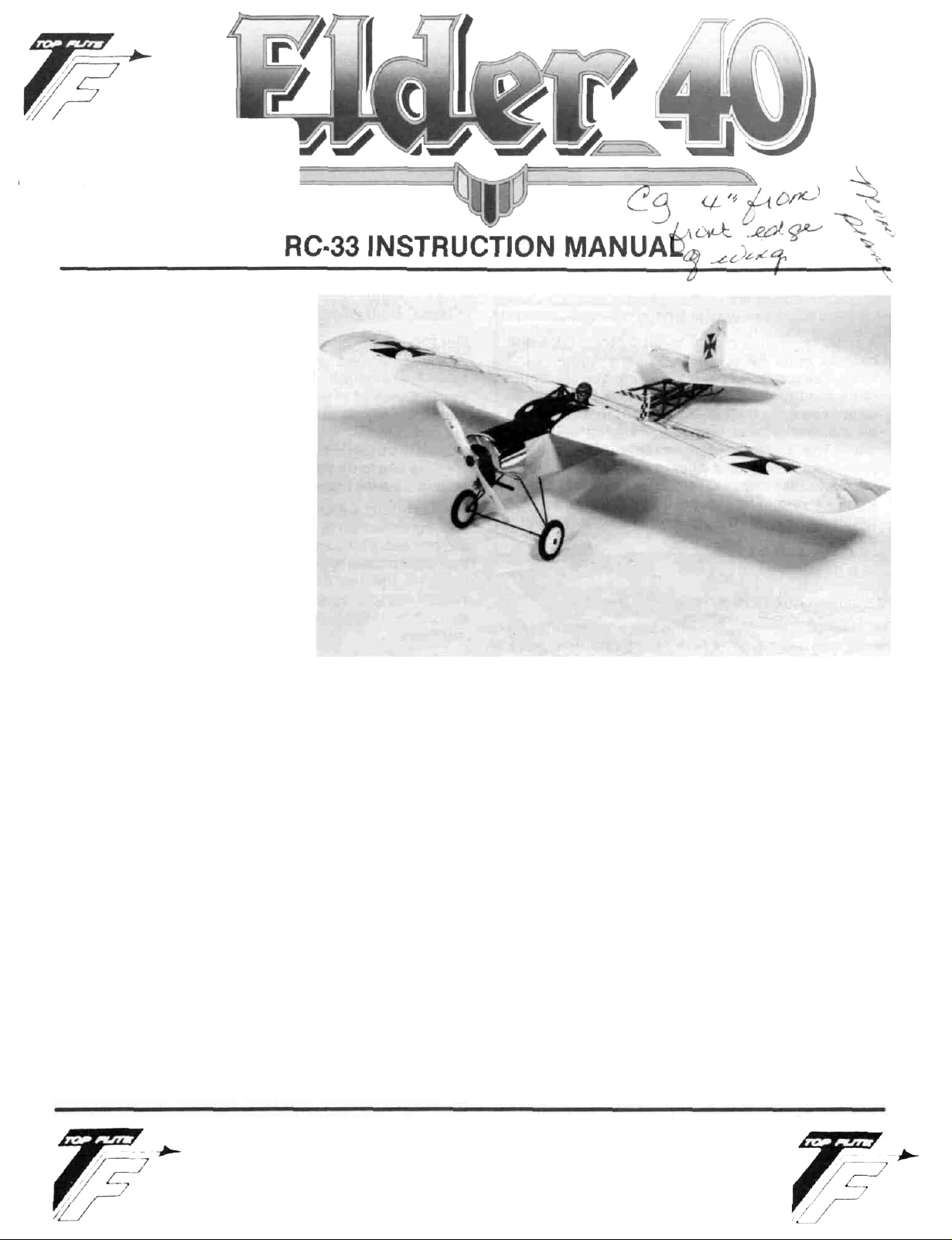
TOP FLITE MODELS, INC. is
proud to introduce the new Elder
40. This design is a direct result
of popular demand after the
great little Elder 20 was introduced. Modelers loved the design,
still do, but wanted something
"larger" and "while you're at it,
give it ailerons." So, here it is and
does it ever fly nice'.
The Elder 40 was designed and
sized expressly for .40 engines
and this includes the popular .40.45 and .49 engines. The design
turns in great performance with
the four-stroke power plants and
there is plenty of power margin
left over for the aerobaticminded pilot. However, the real
"kick" of this design, like its smaller brother, is the
realistic, slow-speed flights that allow you to actually
see the airplane instead of just a blur.
The design lends itself to all kinds of detailing, if you're
so inclined. For the beginner, nothing fancy is needed;
go out and fly it. The Elder 40 makes a remarkably good
training aircraft with gentle and totally honest flying
characteristics. A big bonus here is that your trainer is
just not going to look like everyone else's high-wing,
trike-gear, slab-sided beginner's airplane. In terms of
strength, theEIder40 is a lightly-loaded design that does
not tend to build-up inertia with excess flight speed. This
means that fairly rough handling does not necessarily
mean destruction. While nothing is "crash-proof", the
Elder
40
is a rugged aircraft that will keep coming back
for more.
While we touched on power earlier, a little more should
be said. This design simply does not need a lot of excess
power to fly the way it was intended to. Our experience
has shown us that normal 2-cycle .40's work great as
well as the 4-cycle engine sizes mentioned earlier. With
awing area of just under 800 sq. in., the Elder 40 gets its
tail up quickly and is airborne in just a few feet. Flying
the design with 4-cycle engines is
Give it a try in your Elder
we have provided in the kit may not fit some 4-cycle
engines and it may be necessary to visit your local retail
hobby shop to get the right one for your engine.
IMPORTANT NOTE:
TOP FLITE MODELS, INC. would certainly recommend
the Elder 40 as a first R/C powered aircraft. However, if
you are a beginner to the sport of R/C flying, we would
urge you to seek and use experienced assistance in constructing and flying this airplane. Again, if you are new
to this hobby, consider this:
Flying this or any other radio-controlled model aircraft is
a PRIVILEGE and not a RIGHT and this privilege begins
with the utmost safety considerations to others and
yourself as well. An R/C model airplane in inexperienced
hands has the potential of doing serious personal or property damage. These safety considerations start at the
building board by following instructions, seeking competent help when you are confused and avoiding shortcuts. These considerations have to be carried over to the
flying field where safety must come first and limitations
40.
Note that the motor mount
an absolute delight.
TOP FLITE MODELS INC.
1901 NORTH NARRAGANSETT AVENUE • CHICAGO, ILLINOIS 60639
Page 2

cannot be exceeded. We urge you to:
1. Send for and obtain your AMA (Academy of Model
Aeronautics) membership which will provide insurance for your R/C activities — DO NOT RELY ON
HOMEOWNERS INSURANCE.
2. Join an AMA sanctioned R/C flying club in your area
where you can obtain competent, professional instruction in trimming and learning how to fly this
model.
Check with your favorite local hobby shop for the required AMA forms or the address where they can be obtained.
WARNING!!!
A radio controlled model is not a "toy." Care and
caution must be taken in properly building the
model, as well as in the installation and use of the
radio control device. It is important to follow all
directions as to the construction of this kit as well
as installation and use of the engine and radio
gear. The advice and assistance of a well experienced builder and pilot is highly recommended. Don't take chances! Improper building, operation, or flying of this model could result in serious
bodily injury to others, yourself, or property
damage.
PRE-CONSTRUCTION NOTES
The Elder 40, like other Top Flite kits employs the use of
die-cut wood to ease the task of construction, parts fit
and identification. The dies used for this kit have been
rigorously checked for absolute accuracy and should
provide you with excellent fit. Die-cut parts should be
carefully removed from their sheets by first lightly sanding the back of each sheet of parts and then carefully
removing each part. Use a light garnet paper for the sanding and keep a sharp hobby knife with an X-acto #11
blade, or equivalent, handy for assistance in removing
any parts that might not have completely cut-through by
the dies. Parts which oppose one another and must be
precisely uniform—such as fuselage sides, ribs, etc.—
should be carefully "matched" after their removal from
the part sheets. Matching is the process of holding the
opposing pieces together with either pins, tape or spot
gluing and lightly sanding the edges of the parts until
they are identical. A sanding block with light garnet
paper is most useful for this and other phases of construction.
Your building surface should be at least large enough to
accommodate the wing panels. This surface should be
as absolutely flat as possible and yet be able to accept
pins easily. We have found that a product such as
Celotex fiber board works quite well for this purpose.
Another good surface can be found in most well-stocked
hardware stores—a 2' x 4' fiber board ceiling tile. These
are quite inexpensive and can be used for several
airplanes before needing replacement.
As with most R/C kits that are constructed from wood, a
selection of tools—most of which can be found in the
average workshop—are a must to do the job correctly:
Hobby knife and sharp #11 blades
Single-edge razor blades
T-pins
Sanding blocks in assorted sizes
Sandpaper in various grits
Hand-held hobby saw, such as an X-acto
Dremel tool or power drill and assorted drill bits
Straight-edge, preferably metal, at least 36" long
90" triangle
Soldering iron, flux (silver) and solder
Carbide cut-off wheel for wire cutting
Small power jig-saw, such as a Moto-Saw
Razor plane
Tapes, such as masking and cellophane
Our Elders were constructed using a variety of common
hobby adhesives including 5-minute epoxy, Cyano-
acrylates, aliphatic resin (such as Titebond) and 1-hour
epoxy. Since all of us have our own construction techniques and favorite adhesives, stick with the ones that you
are familiar with and prefer. However, in certain areas
there will be callouts for certain types of adhesives, and
we urge you to try not to substitute since doing so could
possibly cause problems structurally.
The last thing we should touch on before we begin actual construction is the sequence in which the Elder is
assembled. The sequence given to you in this booklet
has been proven to be the most straight-forward and provides the finished components in the order that you will
need them to progress to the next assembly phase. Try
to stick with the building order presented here to avoid
mistakes.
Spread the plans out on your work surface, cover them
with a clear plastic material, such as the backing from a
roll of Monokote or plastic wrap and commence con-
struction.
WING ASSEMBLY
Wing construction for the Elder consists of building
three separate pieces; the two wing panels and the
center section. These will be joined in the Final
Assembly section of this manual. You will need the
center section, with its top unsheeted, during the
Fuselage Assembly section. In this sequence, be certain that you are working on a flat work surface. Carefully join the two wing plan sheets, 3 of 4 and 4 of 4, at the
center section and secure with tape. This provides the
full wing plan on which to work. The wing is built directly
over the plans, so cover them with Monokote backing or
clear food wrap.
1. Start with the center section first. Locate the die-cut
sheets containing parts W-11 (2, ply), W-12 (2, ply),
W-13, two of the W-1A's and W-1 B (4, balsa). Remove
these parts from their sheets and clean up any rough
edges before assembly.
2. Using the plans as a guide; measure, cut and buttglue the
sheet and the 3/32" x 1" trailing edge that makes up
the bottom center section. Note desired grain direction of these pieces. Measure, cut and glue in place
1/4" x 1-1/2"
lower leading edge,
3/32"
balsa
2
Page 3
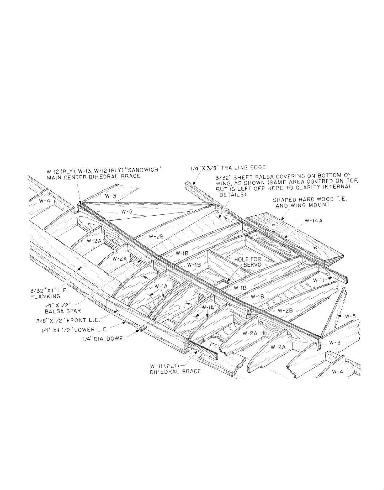
the 3/8" x 1/2" upper leading edge. Glue one of the
W-11 ply dihedral braces in place against the inside
surface of the leading edge—be sure that it's
centered. Glue the outer W-1A half-ribs in place
against the rear face of the dihedral brace, lined-up
with the edges of the bottom sheeting at right angles
to your work surface. Now glue in place two more
W-1A's, 1" inboard of the two outer ones.
3 As shown on the plans, the center dihedral brace is a
composite made by laminating the two W-12's (ply)
to each side of W-13, which results in a 1/4 "thick part
—do this now. Glue the completed composite
dihedral brace in place to the bottom sheeting and
up against the rear edges of the four W-1A's. Be sure
this part is centered.
4 Locate two of your 1/4" x 1/2" pieces of spar stock.
From each, cut one 5" length. Glue one of these
pieces in the top rear slots in the W-1A's and against
the top forward face of the center dihedral brace.
Glue the other on bottom sheeting against the bottom rear face of the center dihedral brace.
5 Now glue the four W-1 B rear half-ribs in place behind
the main dihedral brace. Glue the remaining W-11
(ply) dihedral brace in place on the bottom sheeting
against the rear edges of the four W-1B's. Locate the
1/4" x 3/8" trailing edge material and cut a 5" length.
This is now glued in place against the rear face of the
rear W-11 brace and to the bottom sheeting.
NOTE: For now this completes the center section con-
struction. You will finish it after it has been used in the
construction of the fuselage. Set it aside for now and
build the two wing panels. Both panels are built directly
over the plans at the same time.
3
Page 4

6. In this step we want to prepare each of the required
components—the top and bottom spars, the 3/8" x
1/2" front LE. and the rear
proper dihedral angle at their inboard ends. The
cross-section of the wing that is shown on the plans
is ideal forthis purpose. Simply lay, for instance, the
bottom 1/4" x 1/2" balsa spar in place over this drawing. Note that the outboard end is cut at 90 degs.; but
that the inboard end must be cut at an angle
achieve the required 3/4" per panel dihedral angle.
Make two of these bottom spars. Now repeat this
process with the top spars, the leading edges and
the trailing edges (note that the length of the leading
edges is developed from the top view of the wing
plan). The inboard edges
leading edges should be first cut at 90 degs. and
then slightly chamfered to match the needed
dihedral angle.
7. Start construction by first
lower leading edges in place, directly over the plans.
Note that the inboard edges of these two parts terminate at the outer edges of the two outboard
W-1A's. Next, pin the 3/32" x 1" bottom trailing edge
planking in place. Now glue the 1/4" x 3/8" trailing
edges in place on the top, rear of the 3/32" trailing
edge bottom sheet. Now cut, fit and glue each of the
3/32" x 1/4" bottom cap strips which sit beneath each
of the W-2A's, W-3's and W-4's—pin these in place
over the plan to keep them from shifting. Using the
3/32" sheet balsa provided, measure, cut and glue the
inboard bottom wing sheeting in place—note grain
direction. Glue the W-6 wingtips in place. Now glue
and pin the bottom spar in place (angled end inboard) on the bottom wing sheet and the cap strips.
Now glue all W-2A, W-3 and W-4 wing ribs in place.
Make sure that these are at right angles to your work
surface—pin and allow to dry.
8. Glue all of the W-5 angled ribs in place. NOTE:Toobtain a flush fit, use your sanding block to chamfer the
forward ends of the W-5 ribs where they contact the
W-3 rib sides.
9. Glue all of the wingtip braces (W-7, W-8, W-9, W-10
and W-15) in place on the W-6 wingtip sheet. Note
that W-7, W-9 and W-10 need to have their inboard
ends chamfered with a sanding block to fit flush
the outer face of W-3.
10. Now take the center section which was assembled
earlier and fit ittooneofthewing panels.Tilt it until
thetwoarmsoftheW-11 plydihedral braces fit flush
to the front and rear bottom sheeting and the center
brace is correctly positioned against the bottom
spar. Check this fit to be sure all components fit
nicely. Trim as needed to get proper fit. Prop and/or
pinthiscenter section inthispositionasyouwill use
it as a guide for the remaining wing panel parts.
Remember not to glue anything to the center section
yet; it's only in place for spacing purposes.
11. Glue the front 3/8" x 1/2" leading edge in place on top
of the lower 1/4" x 1 -1/2" leading edge and against the
front of each full and half rib (angled end inboard to
1/4" x 3/8" T.E.
of
the
1/4" x "I11/2"
pinning
the
—with the
to
lower
1/4" x 1-1/2"
to
fit against tilted center section). Glue the top 1/4" x
1/2" spar in place (angled end inboard). Cut, fit and
glue the 3/32" x 1" leading and trailing edge planking
in place—pinortapetohold. Remove the center section from the wing panel and repeat the above steps
on the remaining panel.
12. Cut, fit and glue all of the remaining top 3/32" x 1/4"
cap strips in place on all of the ribs and half ribs.
13.
Remove the wing panels from the work surface. In-
spect them for any dried globs of glue, remove these
with a #11 X-acto knife. Tape or hold the two wing
panels together with the bottoms of each facing the
other—align carefully. Use your sanding block to
now shape the forward wingtips identically with
each other and the curves shown on the plans. With
the exception of the inboard ends, use your sanding
block to carefully "match" the wing panels, leading
edges, tips and trailing edges. Separate the panels
and use a sanding block with light paper over all of
the panels' surfaces to smooth them for covering
later (after final assembly).
14. Note on the plans, the points shown for the 1/4" sq.
spruce flying wire anchor points. These are full rib
depth. If it is your intention to use these optional
wires on your model, cut and glue these anchor
points in place at this time. Set aside the completed
wing panels for final assembly later.
TAIL GROUP
The tail group of your Elder is built directly over the plans
in a quite straight-forward manner. Note there are options open to you with these parts in terms of shape. The
stab's gentle curves which terminate in sharp points
the trailing edge of the elevators give a certain "look,"
which can be changed by rounding the outboard trailing
edges of the elevators. This "softens" the look of these
shapes. The same thing can be done to the fin and rudder, top and bottom—looks nice. As shown, you can
also scallop the trailing edges of the rudder
elevators to give yet another different look.
1. Start with the stab. Build it directly over the plans
which have been covered with the clear backing
from Monokote or food wrap. Position the two S-1
tips in place and the center S-2 as well; pin. From the
1/4" x 1/2" balsa stock provided, cut, fit and glue in
place the two leading edges and the trailing edge.
Using the same material, cut and glue in place the
"cap" in front of S-2, thus completing the stab
outline.
2. Cut, fit carefully and glue the 1/4 "sq. balsa ribs (three
per side) in place. Use short lengths of 1/4" x 1/2" stock
to make the fillets—note grain direction.
3.
From the1/4" x 1-3/4" balsa stock provided, measure
and cut the two elevators. Notch them as shown
accept the 1/4" dia. dowel elevator joiner. With the
stab still in position on the work surface, pin the
elevator halves in place. Protect the trailing edge of
the stab with a strip of waxed paper and epoxy the
dowel joiner in place in the notches—allow to set
completely.
at
and
to
4
Page 5

4. Remove the stab and elevators from the plans. Build
the fin next in the same manner using the R-1 and R-2
die-cut pieces with 1/4" sq. and 1/4" x 1/2" balsa frames
shown. Cut the rudder to shape from the remainder
of the
1/4 " x
1-3/4"
balsa stock used for the elevators.
Position the rudder in place to the back of the fin and
glue R-3 in place to the leading edge of the rudder.
Remove the parts from your building board.
5. Using the 3/32" x 1/4" balsa provided, cap strip both
sides of the fin and stab assemblies as shown on the
• plans. Be sure, when capping the lower edge of the
fin, to leave a distance of 3/32" from the bottom to
allow the fin to fit into the slot between the two top
S-3 caps. Glue the two S-3 caps to the upper surface
of S-2, leaving a 1/4" gap at the centerline for the fin.
Test-fit the fin in place on top of the stab. With the fin
still in place, cut, fit and glue the forward 3/32" x 1/4"
cap strip in place forward of the fin. Remove the fin.
6. The elevators, stab, fin and rudder are now finalsanded to shape. Start by using masking tape to
mount the elevators to the stab. Use a sanding block
to go over all of the outside surfaces to carefully
match them. Lay the stab on a flat working surface,
masking tape down, and use the sanding block to
sand it flat. Use the sanding block to taper the
elevators as shown on one side. Tape the
stab/elevator hinge line, turn the stab over, remove
the tape from this side, and repeat the process. The
same method is used for the fin and rudder. Once
complete, use sandpaper to round the leading
edges. Set these parts aside for covering and
assembly to the fuselage.
FUSELAGE ASSEMBLY
Before starting construction, study the plans and draw-
ings to familiarize yourself with how the fuselage is
assembled. Note that it really is nothing more than a
basic "box" fuselage with semi-formers in the nose area
to create the rounded cowling effect. This simple and effective way of making a fuselage can only be ruined in
one way; building it crooked. This can be done by not
making the fuselage side frames identical and/or missizing the top and bottom cross braces. Another common error is to make improper joints. The Elder relies a
great deal on the strength of its frame—make those
joints fit correctly! Note also that the uprights and cross
braces are a mix of both spruce and balsa. These are
notated.
1. Locate and remove die-cut parts F-5 and F-9, two of
each. Securely pin F-5 in place directly over your
covered fuselage plan. Note that the bottom aft
spruce longeron terminates in the rear notch in part
F-5. Disregard the curve of this longeron for now.
2. Pin F-9 in place directly over the plans. Measure and
cut the top rear spruce longeron that fits in place
from the back of the "tab" on F-9 aft to the tail post.
(A tool such as an X-acto mitre box and razor saw is
quite good for cutting spruce.) Glue the top rear
longeron in place to F-9.
3. As you can see from the plans and building sketches, the top 1/4" sq. spruce longeron fits in place
from the front edge of the
1/4" x 1"
x
3-5/8"
ply wing
hold-down former. Eventually, when it is installed,
this
ply former will be backed-up with a 333/8"
length
of 1/4" x 1/2" balsa. Hold this former on edge with a
piece of 1/4" x 1/2" behind it and mark its forward location on F-9. Cut a length of 1/4" sq. spruce to fit from
this mark forward to the front face of the
firewall-
glue in place to F-9.
4. Cut, fit and glue the four required 1/4" x 1/2" balsa
uprights from Cross-Section B-B back to and including the one beneath the "tab" on part F-9—note
that the bottom, rear longeron will need to be blocked in place as the bottom, rear curve starts. As
shown on the plans, a 1/4" balsa doubler is made to
fit inside of the fuselage frame, at the nose, between
F-5 and the top longeron and against the front of the
1/4" x 1/2" upright at Section B-B. This doubler is cut to
fit 1/4" behind the top longeron in order to accept the
firewall. Glue this doubler in place.
5. Cut, fit and glue in place the rearmost 1/4" sq. spruce
tailpost upright—be sure that the correct angle is
also trimmed into its lower end for the bottom
longeron. With the frame firmly secured to the
building board, bend the bottom longeron up to meet
the rearmost upright that was just installed. Glue
and securely block this longeron in place.
6. Cut, fit and glue in place all remaining spruce
uprights while bending and block-pinning the bot-
tom, rear longeron in place as you go. This completes the basic fuselage side frame. Now make a
second, identical frame. Be absolutely sure that
they're identical by building the second frame
directly on top of the first, carefully covering the first
frame with Monokote backing or food wrap.
7. Hold or tape the two completed frames together and
use your sanding block to make sure they are identical. Separate them and sand their sides smooth
(both sides) with the sanding block.
8. Note on the side view of the plans for the fuselage
that there are six 1/4" x 1/2" balsa cross-brace locations shown (numbered 1 through 6). All of these
cross-braces, with the exception of #3 (directly
beneath the wing's trailing edge) are 3-1/8" long.
Carefully cut all
five
to length.
#3
is 3-5/8" long,cut
this one as well. Carefully position the two fuselage
frames upside down, over the top view of the plans.
Block or pin as needed to hold them in place at right
angles to your work surface. (NOTE: Due to the slight
incidence angle in these frames, they will not fit flat
to the surface. This is not important at this time.)
Locate two of the1/4" x 1"
x3-5/8"
ply formers. Epoxy
these in place in the notches located on the bottoms
of the F-5's. Glue bottom cross-braces 4, 5 and 6 in
place between the two fuselage frames and allow to
set. Remove the frame from the work surface, turn it
over and install the three remaining cross-braces, 1,
2 and 3 in place. Now epoxy the remaining 1/4" x 1" x
3-5/8" ply
wing
hold-down former in place on top of
F-9.
5
Page 6

IN THE FIRST STEP, THE FUSELAGE SIDES ARE ASSEMBLED DIRECTLY ON
FUSELAGE PLAN TO KEEP FRAME FROM BEING GLUED TO PLAN, USE
MONOKOTE BACKING OR CLEAR PLASTIC FOOD WRAP WHEN FIRST SIDE
HAS BEEN ASSEMBLED, AGAIN USE CLEAR PLASTIC SHEET TO KEEP
SECOND SIDE FROM ADHERING TO THE FIRST SIDE FRAME
ALL UPRIGHTS 1/4" SQ. SPRUCE
AFT OF THIS LINE
ALL UPRIGHTS 1/4" X 1/2" BALSA
FORWARD OF THIS LINE
IN
THIS "FIRST STEP"
SECOND SIDE HAS BEEN MADE
AND IS SEPARATED FROM
FIRST SIDE BY PLASTIC
SHEET.
SKETCH,
1
1/4" SQ. SPRUCE LONGERONS
CLEAR PLASTIC
SHEET
2
FIREWALL
3
1/4"
PLY,
1"
X 3-5/8"
9. Locate the 1/4" ply firewall. You must now use the
plans to locate the position of your motor mount on
the firewall. This mount is installed inverted. Mark
the location of the four mounting holes onto the
firewall. Use a drill to drill the holes through the
firewall with a 1/8" dia. bit. Epoxy the four 4-40 blind
THE FIRST PHASE OF SHEETING IS
SHOWN IN STEP
WITH GRAIN ACROSS THE FUSELAGE)
STEP 2 - JOIN BOTH SIDES WITH 1/4"X 1/2" BALSA
CROSS PIECES AS SHOWN ALSO GLUE FIREWALL
(1/4" PLY-3-3/8" X3-5/8") IN PLACE
STEP 3-ADD THREE 1/4" PLY (1" X3-5/8") CROSS PIECES AS
SHOWN (TWO ARE L G MOUNTS, ONE AT FUSELAGE TOP) THEN
BEVEL INNER REAR ENDS OF FRAMES AND GLUE TOGETHER.
CUT REMAINING CROSS PIECES TO SIZE (BEVEL ENDS FOR AN
EXACT FIT) AND GLUE IN PLACE.
3--(1/8"
SHEET,
APPLIED
mounting nuts in place to the back of the firewall into the holes just drilled—keeping adhesive out of
the threads. Test mount the motor mount with the
4-40 x 7/8" bolts provided. Remove the mount and
epoxy the firewall to the front of the fuselage frame.
Align it carefully and allow to cure.
6
Page 7

10. Use your sanding block and medium sandpaper to
now go over the frame. Make sure the edges are all
square and clean.
11. Locate and assemble, if needed, the fuel tank that
you plan to use. This airplane can use either 8,10 or
12 oz. fuel tanks. (We show the Du-Bro 12 oz. fuel tank
mounted upright in the nose.) Fit your tank into the
nose-of the fuselage frame. Use short (3") lengths of
scrap balsa stock to make "support" for it. With the
fuselage open at this time, it's easy to see if the tank
will sit level—adjust as needed. In this way, when
the fuselage is done, your tank can be inserted from
the wing opening into the nose and removed, if need-
ed, with assurance that it is mounted correctly. Now
use a 3/16" drill bit to drill the two required holes for
the fuel tank (one for fuel feed and filling and the
other for the pressure tap and overflow). Remove the
tank.
12. Drill and tap the holes necessary in the motor mount
to attach your engine (we like to use 4-40 Allen-head
bolts for this purpose). Attach the motor mount to
the firewall and the engine to the mount. By viewing
from the front, determine the location of the throttle
tube housing exit hole. This should be lined-up with
the carb's throttle arm. Drill a 3/16" dia. hole through
the firewall for this tube. Rough-up the outer surface
of the outer throttle tube housing and glue it in place
in the firewall—about 3/16" of it should protrude out
from the face of the firewall, the rest of it runs into
the radio compartment. Be sure your tank still fits
nicely.
13. The servos shown on the plans are of average configuration; however, yours may be different (taller,
wider, etc.). The Elder will accept almost any radio
system. Lay the fuselage frame over the side view of
the plans and lay one of the servos in place.
Remember that these servos will be mounted on the
1/8" ply servo tray. Observe if your servos will fit. Cut,
notch, fit and glue the 1/4" x 1/2" balsa servo tray
bearers in place between the two uprights in the
radio (servo) compartment. Their outer edges should
be flush with the rest of the fuselage frame.
14. You can now sheet the bottom of the fuselage from
the nose (between the two landing gear formers)
back to the 2nd bottom 1/4" x 1/4" cross brace—don't
sheet any further back. Note this sheet is applied
cross grain. Use your sanding block to sand the
edges flush with the frame sides. Sand the landing
gear mounts and sheeting to a smooth curve when
viewed from the side.
15. Use the 1/8" x 6" x 21" balsa to now make the primary
fuselage sides. Lay the fuselage frame on the sheet
with the forward edge of it lined up with the vertical
line at Section B-B. Use a pencil to trace the fuselage
side outline onto the sheeting. Cut out the fuselage
side and glue it in place, repeating the process for
the other side. Use your sanding block to again true-
up edges and generally tidy the fuselage.
16. Stand the fuselage on its nose, firewall flat to the
work surface. Locate and glue in place the two side
F-4 formers to the firewall sides and flush with its
front face.
17. Locate and glue half-formers F-6 and F-7 together
(note that the bottoms of these formers are flush
with one another thus providing a 1/8" shelf around
the outside for the nose sheeting). Now accurately
glue the F-6/7 former in place across the fuselage at
Section B-B.
18. Locate and accurately pin in place the wing center
section to the top of the fuselage—take your time
and locate it as accurately as possible. Use a 1/4"
dia. bit to drill through F-6/7, the leading edge and
dihedral brace of the center section (backing up the
dihedral brace with a piece of scrap wood avoids
splintering as the drill bit pass through). Remove the
center section and set aside for now. Once again,
stand the fuselage on its nose, flat on the work surface and glue the top F-3 former in place on top of the
firewall and flush with its front face.
19. Measure, cut and glue in place the top 1/4 " sq. balsa
cowl longeron, which fits from the notch in F-6,
through F-3 and out to the F-2 location. Cut, fit and
glue the two side1/4"
fit in the notches provided in the F-4's. Temporarily
install cowl former F-2 in place on the three ends of
the cowl longerons. Observe how this former is sitting in place. Viewed from the side and top, it should
be parallel with the firewall. Use a ruler to be sure
and trim the ends of the longerons to achieve this
goal. Once satisfied, glue F-2 in place to the ends of
these longerons. Now cut, fit and glue the 1/4" sq.
balsa sheeting support pieces (2) that fit from the rear
face of the F-4 back to the uprights at Section B-B.
Note these are angled and must be beveled to fit.
Now glue the forward cowl former F-1 in place to F-2,
leaving a 1/8" shelf" around its perimeter for the
cowl sheet. Lastly, glue the two required lengths of
1/4" sq. balsa in place from the bottom, outside corners of F-1 down to the bottom, outside corners of
the F-4's. Bevel the ends of these to fit correctly.
20. The sheeting sequence diagram illustrates exactly
how and in what sequence the nose and cowl is
covered. Wetting the 1/8" balsa sheeting helps it to
conform to the required curves. Take your time to
achieve an accurate, gap-free fit before glueing
these pieces in place. CA adhesives work very well in
this area, eliminating the need for pins. If you have
taken
your time
a minimum of gaps, all that remains is sanding to
shape.
21. Use a sanding block to bevel the inside ends of the
spruce fuselage framework at the tailpost—see
plans. Once satisfied, glue these ends accurately
together providing equal bends to each side of the
fuselage when viewed from the top. Accurately cut
six (6) pairs of top and bottom 1/4 " sq. spruce crossbraces which will fit from Section C-C back to the
tailpost. We suggest cutting the top and bottom
braces at the same time to ensure equal length. Glue
these in place, working from the front to the back.
sq. balsa cowl longerons which
and fitted these pieces in place with
7
Page 8

SHEETING SEQUENCEFRONT OF FUSELAGE
NOTE THAT EACH PIECE OF 1/8"
SHEET BALSA IS APPLIED
"BY THE NUMBERS"
OPPOSITE SIDE IS
COVERED IN A
SIMILAR MANNER
Again, accurately position the wing center section
assembly in place on the fuselage, its leading edge
against F-7. Locate the tapered hardwood center
section's trailing edge and part W-14A. Hold these
two parts in place against the center section's trail-
ing edge and, with a pencil, draw a line across the 14"
x 1/2" balsa cross-brace to indicate where the top,
rear fuselage sheeting begins. Remove and setaside the center section and the other parts for now.
Finish sheeting the fuselage with cross-grained 1/8"
balsa, from the line just drawn to where the fuselage
sides end.
With the exception of final sanding and rounding as
shown on the plans, the fuselage is now complete.
LANDING GEAR AND TAILSKID ASSEMBLY
The pre-bent front and rear 1/8" dia. M.W. landing gear
(L/G) forms must be joined together at the bottom,
towards the wheels. We recommend soft copper wire for
firmly wrapping the two pieces together prior to soldering. We would highly recommend the use of HARRIS'S
REDUCED SIZE DETAIL OF
ALL FIVE PIECES BUTT-
JOINED TOGETHER
STAY-CLEAN FLUX and their silver solder for this operation. Although a soldering iron will work, with patience,
these joints can be quickly and permanently made with
the use of a small hobby-type gas torch.
1. Locate the position of the rear "cross-axle" wire to
the bottom rear ply L/G plate on the fuselage bottom.
While holding the wire in place, slip the two formed
metal clips onto the wire. Use a pencil to mark the
hole locations of these clips onto the ply base, then
remove the wire and clips. Drill shallow, smalldiameter "guide holes" for the clip's screws. Now
attach the landing gear wire to the fuselage with the
clips and the #2 x 3/8" screws provided—no need to
overtighten. Repeat this process with the forward
landing gear wire.
2. Pull the two components together until they touch.
The two short bent "arms" on the forward leg should
line-up with the legs of the rear L/G wire. If needed,
use pliers to adjust these arms until they fit neatly.
3. Use soft copper wire to neatly wrap the forward short
8
Page 9

OPTIONAL
DECORATION
DETAIL-
1/4" LENGTHS OF 3/32" OR 1/8" DIA. PLASTIC
TUBING CAN BE EPOXIED INTO EACH JOINT
BETWEEN A SPRUCE CROSS BRACE AND
UPRIGHT (16 PLACES). LATER,"RIGGING" IS
THREADED THROUGH EACH TUBE, DRAWN
TIGHT AND EPOXIED IN PLACE.
arms to the rear L/G wire as shown on the plans. App-
ly some STAY-CLEAN flux to the joint and solder.
Repeat the process on the other side. Be neat and try
to be sure that the joint is solid without a lot of ex-
cess solder. Once satisfied, completely clean the
solder joints of any flux.
4. As shown, the crossed-axle landing gear system
FRONT AND REAR
STRUTS ARE BOUND
TOGETHER WITH FINE
COPPER WIRE,THEN
SOLDERED
THOROUGHLY.
derives its ability to accept landing loads and shock
from the two (2) independent axle legs. These need
to be joined
wheels. This distance has shown very good shock-
absorbing ability for Elder's weighing 4 to 6 lbs. Join
these axles
quired, wrapping with soft wire (about 1/2" ) and
soldering. Again, clean the solder joints completely.
at
two points, each
by
first measuring the
2-1/2"
2-1/2"
in
from the
distance
re-
FOR PERMANENCE.
RETAIN WHEELS ON
AXLE WITH WASHERS.
SOLDERED IN PLACE.
ALTERNATE METHOD
IS TO USE WHEEL
COLLARS.*
BIND AXLE SECTIONS OF LANDING
GEAR TOGETHER WITH THIN COPPER WIRE,
THEN SOLDER PER DIMENSIONS SHOWN.
9
Page 10

5. The same process is now used to make the rear
tailskid assembly. First bend the 1/16" dia. M.W. provided to the shape shown using pliers. Wrap the tip
of the skid with soft copper wire and solder. Now
tapethe main skid wire in place tothe bottom rear of
the fuselage. Locate the pre-bent tailskid support
wire and wrap it in place to the tailskid with soft wire.
Solder it in place to the skid. Remove the assembly
from the fuselage and again, clean the solder joints
completely.
6. Remove the main landing gear from the fuselage.
The landing gear and tailskid are now complete and
can be used as is or painted flat black or aluminum
(we use epoxy paints for this as well as other painting needs on this airplane). As we did on some of our
prototypes, you may wish to add wood backing to
the wires. Sand these to airfoil shape and paint them
a wood color—looks great! We used 1/8" x 1/4" hard
balsa with a 1/8" dia. "groove" sanded into one edge,
carefully fitting the piece in place. We glued the
wood to the metal with thick CA adhesive and sanded the whole affair smooth. Then we used clear,
paintable Monokote to cover the "wooded" parts of
the landing gear to provide a one-piece look and airbrushed wood-colored epoxy paint on the whole
thing.
FINAL ASSEMBLY
1. Locate one of the 1/4 " dia. x 36" dowels provided in
your kit and cut a 3" length, this to be used for the forwardwing hold-down. Insert this dowel intothewing
center-section,
leaving 1/4"-3/8" of it exposed in front
of the leading edge to engage the F-6/F-7 former
assembly with the previously drilled hole. Now install the center section in place on the fuselage with
the dowel engaging the hole in F-6/F-7, again being
sure that it is squarely in place. Liberally apply epoxy
around and beneath this dowel, in the wing center
section area. Next, position and glue in place the
two remaining W-1A half ribs into position on each
side of the dowel. Fill the resulting cavity above the
dowel with more epoxy and allow the structure
cure.
2. Remove the center section from the fuselage. Carve
and sand the short leading edge section to shape,
matching the two leading edges of the wing panels.
3. The two wing panels can now be permanently at-
tached to the wing center section. We recommend
that you use epoxy for this operation. With the
center section flat on your building surf ace, slide the
two panels in position onto the exposed arms of the
front, center and rear dihedral braces. The fit should
be accurate; the front brace fits against the back
face of the panel's leading edge, the center brace is
in contact with both the top and bottom spars and
the rear brace is inside of the top and bottom rear
trailing edge sheet strips. The panel's spars, leading
edges and trail ing edges should also be cleanly contacting the outside surface of the center section's
sides. Take time here to ensure that this is the case
to
before committing to actual attachment. Locate or
make a couple of 3/4" high supports for the wingtips
to provide the required dihedral angle. Now epoxy
the panels in place to the center section—don't use
so much glue that it runs or drips but enough to provide a good glue joint. One-hour epoxy is best for this
step. Allow the structure to cure completely.
4. As shown on the plans, a forward and rear "cockpit"
former was made from 3/32" sheet, placed in-between
the two inboard W-1 B's, full-depth to these two ribs.
Be sure that the forward cockpit former is far enough
back to allow insertion of your aileron servo.
5. The two inboard panel rib bays (between W-2B and
W-1 B) and the center section can now be completely
sheeted, cross-grain, as shown. We have found that
it is helpful, when glueing this sheeting in place, to
"share" the width of the center section's outboard
W-1A and B ribs with both the wing panel and center
section's sheeting edges, thus providing a glueing
surface for both. When dry, use sandpaper to
smooth the wood and to match the sheeting with the
leading edges.
6. In this step you are going to assemble the hardwood
trailing edge and aileron torque tubes and wires to
the wing center section—please refer to the detail
drawing provided to understand the parts relation-
ship. Glue the two W-14B's in place to the forward
face of the hardwood trailing edge, their outboard
ends flush with the outboard ends of the trailing
edge. Note that there is a right and left aileron drive
assembly. As shown, the trailing edge must be
grooved a little to allow aft movement of the threaded linkage arms. Do this now with either a rat-tail file
or a Moto-tool and router bit. Now glue W-14A in
place, thus providing a "nest" for each of the torque
rod assemblies. As shown, knock-off the corners of
W-14A to allow torque rod movement. Rough-up the
brass sleeves on each of the torque rod assemblies
and carefully glue them in place with one-hour epoxy
—do not get adhesive on the torque rod arms.
1/4" X 3/8'; T.E. (NOTE CLEARANCE
SLOTS FOR AILERON TORQUE
ROD MOVEMENT)
SHORT BENT LEG FITS HOLE
AND TUBE IN ROOT END OF
SHAPED AILERON (SEE
WING
THIS LEG OF
AILERON TORQUE
ROD CONNECTS TO
SERVO LINKAGE
SHAPED HARD WOOD WING
MOUNT (NOTE CLEARANCE
SLOTS "X") TO ALLOW FORE
AND AFT MOVEMENT OF
AILERON TORQUE ROD ARM
DETAIL OF WING CENTER SECTION
AT TRAILING EDGE
(AS SEEN FROM BELOW)
10
Page 11

Now position the trailing edge/torque rod assembly
against the trail ing edge of the wing's center section
—lightly use a sanding block to "true-up" this joint
as needed. While holding this assembly in place,
move each threaded linkage arm forward to dent the
balsa on the bottom of the center section. Remove
the trailing edge assembly and use a file or Motetool to groove the wing's center section at the two
dents just made to allow forward movement of the
linkage arms. Once satisfied with the movement of
these arms, the hardwood trailing edge assembly
can be epoxied to the trailing edge of the wing.
Again, be careful to avoid adhesive getting into the
area of the linkage arms; you want them to move
freely.
7. Once again, accurately pin and/or tape the wing in
place to the fuselage. Use the plans for reference to
now drill two 1/8" dia. wing bolt holes through the top
rear of the center section and through the 1/4" ply
former directly beneath it—note the angle that these
two holes are drilled at to take into account the slope
of the top airfoil at that point. Remove the wing from
the fuselage. Tap the two holes in the ply former with
either an 8-32 tap or an 8-32 metal bolt. Once the
threads have been established use a little thin CA
adhesive to "coat" them and then run the tap into the
holes once again; this toughens-up the threads. It
may be necessary to run the tap or bolt through
these threads several times to allow the nylon 8-32
bolts to clear. Use a 3/16" drill bit to now "clear-out"
the two 1/8" holes in the wing center section for clear
passage of the wing bolts. Now bolt the wing in
place on the fuselage.
8.
Locate die-cut former F-8 (balsa). As you can see
from the plans, this former is trimmed at the bottom
(sanding block) to fit onto the top of the center section's leading edge where it becomes the "shelf" for
the 3/32" x 1/4" fuselage fairing strips. Apply glue to
the bottom of this part and position it accurately in
place on the center section, flat against the rear face
of F-7— don't get glue on F-7. Start making the
fuselage/wing fairing by first cutting to length the
top center 3/32" x 1/4" balsa strip, the center one when
viewed from the top. Sand its rear bottom edge to
match the countourof the center section's sheeting.
Once satisfied, carefully glue in place to the top of
F-8 and the center section sheeting. Repeat this pro-
cess to the left and right of this center strip until the
rough fairing is complete. With the center section
still in place, use your sanding block and sandpaper
to now smooth the fuselage/wing joint to a one-
piece look. Any small gaps or rough edges can be fill-
ed with a filler such as DAP White Vinyl Spackling
compound and sanded smooth again. Remove the
wing from the fuselage.
9. Now make the cockpit cut-out in the wing center section. The pattern, provided on the plans, can either
be traced or the pattern itself cut-out of the plans to
serve as a cutting guide. Use a #11 X-acto knife for
this purpose and try to be as neat as possible.
10. Note the aileron detail drawing directly beneath the
left wing panel plan. The ailerons will need their
leading edges sanded in this manner to facilitate
non-binding movement (do this now). Next locate
and drill the 1/8"dia. hole in the inboard leading edge
of each aileron that will engage the exposed torque
rod ends. These holes are now sleeved with the two
lengths of 1/8" O.D. brass tubing in your parts bag.
These should be roughed-up and epoxied carefully
into the holes in the ailerons. Now use a Moto-tool to
make a groove from these holes inboard to the
aileron ends. These grooves will hold the torque rod
arms and allow the ailerons to fit up to the wing's
trailing edge.
Using a #11 X-acto blade, carefully locate and cut
each of the nylon hinge slots in both the aileron and
wing trailing edge—5 hinges per aileron. Trial-fit the
ailerons to the wing panels and torque rod arms. Do
any trimming necessary to facilitate free, non-
binding movement. With the ailerons temporarily
hinged to the wing, use your sanding block to now
sand the entire assembly to final shape. Remove
ailerons and hinges, set aside for covering.
11.
Cut four
each of the two 36" lengths provided). These are now
used to make the "king post" that fits to the wing
center section. This assembly is most easily made
by first constructing two separate triangular pieces
and then joining the two pieces at the top. Chamfer
the top ends to fit as shown on the plans and epoxy.
The bottom ends must also be chamfered to sit
squarely on the top surface of the center section,
just ahead of the cockpit. Do not attach the finished
structure yet, it will be assembled to the wing after
covering.
12.
Locate the two required rear fuselage pushrod exits
(die-cut ply). Clean theiredges with asanding block.
Note their location on the plans—directly beneath
the stab. Glue in place.
13. A 1/16"x 1/2"x 12 "ply strip is provided for the fuselage
frame "joint caps". The drawing on the fuselage
plan depicts how these are to be cut using scissors
or shears. These are now carefully glued in place to
each of the exposed fuselage upright and cross
brace joints as shown on the plans. Once these are
in place, use sandpaper to lightly smooth their
edges.
14.
Use a #11 X-acto blade to now make the hinge slots
(six total) in the elevators and stab—note their loca-
tion on the plans. Temporarily install the elevators in
place. Now cut the two required hinge slots in the fin
and rudder. Note on the plans that you will now have
to clear-out a semi-circular opening at the leading
edge of the rudder to allow it movement around the
elevator joiner. This allows the rudder to fit in place
against the fin when hinged. Once satisfied that all
movement is free and non-binding, disassemble
these parts and set aside for covering.
15.
As shown on the plans, we used short lengths of in-
ner throttle pushrod tubing to make the stab and fin
flying wire brace points. These should now be glued
4 1/2"
lengths of 1/4" dia. dowel (two from
11
Page 12

in place in pre-drilled holes.
16. Although we have been instructing you to sand the
various components of your Elder as you were constructing them, take the time to now re-check
everything that may require final touch-up and/or fill-
ing. The difference between a good covering job and
a great one tends to be about $2.00 worth of sand-
paper and the willingness to use it.
COVERING & FINISH
Now that all of the various components of your Elder are
completely assembled and sanded to their final shapes,
you can turn your attention to covering. This is the point
that can separate your model from anyone else's. You
must decide what you want the finished airplane to look
like. We have finished our prototypes in a wide variety of
color schemes representing everything from an R.A.F.
WWI fighter (in cream Monokote with red, white and blue
Roundels and tail treatment) or a German WWI fighter
(all red Monokote with black Iron Cross's on a white
background) to civilian-type versions (dove gray
fuselages, transparent blue wings and tail-group and
chrome Monokote "cowls")! Interestingly, no matter
what color scheme we used, there was always a group of
people at the flying site who would stand there looking
at the Elder, arguing about what real, full-scale aircraft it
represented. Just remember that the Elder is not a scale
model, you're free to cover it in any configuration that
strikes your fancy—it will look great!
Before covering, it is suggested that the final finish be
applied to the open spruce fuselage structure. This can
be done several ways. There is a very good product on
the market called Varathane that is sold through most
well-stocked hardware and lumber supply outlets. This
material is essentially clear and will leave the spruce
about its same color, maybe a little darker, and
somewhat shiny. It is resistant to spent fuel and quite
durable in actual use. Epoxy paint, mixed to achieve a
woodish brown color and brushed or sprayed, also
works well. Take your time here, use light sandpaper to
go overthe framework, smoothing it forthe finish of your
choice. When applying the finish, be sure that all of the
exposed wood, except the top, rear stab glueing area,
receives paint. We then used flat black paint (again,
epoxy is great) to paint each of the ply "joint-caps." This
really makes the structure come to life!
Now for the covering itself. Use the directions that are
supplied with each roll of Monokote and cover each of
the various components separately; fuselage, wings,
stab, elevators, fin and rudder. Some of you might have a
problem with the wingtips of the Elder, if this is your first
venture into the use of Monokote or your first R/C
airplane. Here's a method that works quite well. First,
cover the wing panels totally, starting with the bottoms
first, including the wingtips. Then cover the tops of the
wing panels out to and including the last outboard W-3
wing rib, but not the wingtips themselves. Next, cut an
elongated triangular piece of Monokote to fit over the
space between the forward W-3 rib and the forward W-7
wingtip former—keep the edges straight, allow about
1/8" overlap and iron this piece in place. Move now to the
next exposed triangular area between W-7 and W-8 and
repeat the process. This method will provide a much
easier covering situation for the newcomer and, if done
carefully, gives you a nice looking, wrinkle-free wingtip.
When covering the fuselage be sure that the bottom
covering—the piece that you should apply
first—overlaps into and on the firewall by about 1/4" at
least.
Assuming that the airplane is now covered, turn your attention to fuel-proofing the engine compartment. We
like to use and highly recommend a liberal coat of
polyester resin. Coat inside the cowl and fuel tank areas and over all of
the Monokote seams that terminate in the cowl itself.
This seals the wood as well as the Monokote seams and
avoids "fuel creep" later on. Be sure to keep the resin out
of
the bolt holes in the firewall.
Use your X-acto knife to now clear-out all of the hinge
slots in the ailerons, wing and tail group. Do the same
thing for the wing hold-down bolt holes, the cockpit, the
landing gear screw holes, etc.
Mount the wing to the fuselage with the nylon bolts.
Place the stab in position on the top rear of the fuselage
and sight down the front of the model to observe if the
stab is sitting flat in relationship to the wing, without any
tilt. Once satisfied, hold the stab firmly in place in the
position that it is meant to be; square with the fuselage
and aligned correctly with the wing when viewed from
the top—make sure that it is exactly where you want it.
Use a sharp pencil and, while holding the stab in place,
trace the outline of the framework that is in contact with
the bottom of the stab onto the stab itself. Remove the
stab from the fuselage. Use your X-acto knife to now
lightly cut-out the frame outline from the bottom of the
stab's Monokote to expose the wood—this will be your
glueing surface. The stab can now be mounted to the
fuselage; we used a "thick" CA adhesive for this.
Next, prepare the fin for mounting to the stab by making
sure that all covering is removed from the bottom of it,
leaving exposed wood. Be sure that the covering on the
top of the stab is well-adhered to the center S-3's
because you will be removing some of it, at the center, to
accommodate the fin. Use your X-acto knife to remove
the covering from the fin slot location, exposing the
wood. Before glueing the fin to the stab, use a pin to
make lots of small holes in the exposed wood of both the
stab and fin bottom, these need not be deep. Use a
slower drying adhesive (Titebond, 1-hour epoxy, etc.) to
now glue the fin in place on the stab. Use a length of light
tape over the top of the fin and on each tip of the stab to
hold the fin in place, at right angles, and allow to dry.
Check periodically while this structure is drying to be
sure that the fin has not shifted and is in place at right
angles to the stab and on the centerline of the fuselage;
we want everything "square." When this structure is dry,
remove the tape. Thread a length of 20# fishing line (used for rigging thru-out, if desired) through the hole at the
top of the fin and glue each end of the line into the holes
at each tip of the stab—carefully applied "thick" CA
12
Page 13

adhesive will work well. The fin should now be quite immobile on the stab.
Use 1-hour epoxy to now glue the hinges required into
the trailing edges of the wings, stabilizer and rudder.
Next, mount the elevators to their hinges followed by the
rudder and ailerons. A little acetone or CA debonder on a
clean paper towel can be used to clean-off any glue that
has oozed out of the hinge slots.
Mount the landing gear assembly to the fuselage with
the screws and clips provided. Mount the clips securely
but do not over-tighten.
Now install the motor mount to the firewall. Use one or
two washers behind the top two motor mount bolts to
give about 2 to 3 degrees of down-thrust. Mount your
engine to the motor mount; we suggest 4-40 Allen-head
bolts into pre-tapped holes. Cut two lengths of fuel tubing with sharp angles at one end. Insert the angled ends
into their holes in the firewall and use a pair of long-nose
pliers to reach into the fuselage and pull them almost
through the tank compartment. Trim the ends of the tubing and connect them to the appropriate tubes on your
tank. Now pull the tubes back through the firewall while
moving the tank into the fuselage. Trim the tubing to
length and make the connections to your engine and
pressure tap.
The triangular-shaped "flying-wire post" that is shown
sitting in front of the cockpit can now be glued (epoxy) in
place by first positioning it on the top of the wing to
determine its final position.Once satisfied, presson the
top of it, indenting the covering slightly. Remove the
covering material within these indentations, exposing
wood and glue the post in place. If you have decided to
add the optional flying wires (20#-test fishing line), drill
small holes
(1/32" dia.)
into the tops of the spruce upright
posts that you installed during wing construction. We
used very small cotter pins for the flying wire anchor
points, these can now be epoxied into the holes. Before
adding the flying wires, apply any decoration or markings to the wings, then add these wires.
As shown on plans, the exposed framework of the aft
fuselage is shown with bracing wires and tubes in each
joint corner for their attachment. If you have decided on
this as an option, now is the time to add them.
The
1-3/8" x 2-3/4"
windscreen is now
trimmed
to shape
using the outline provided on your plans and glued in place
just ahead of the cockpit opening. Position the bottom
edge of the windscreen in place on the wing center section and press down to leave an indention. Use an X-acto
knife to cut through the indention and wood beneath it.
The windscreen can now be inserted into this "slot" and
held in place with a small amount of adhesive. If you are
using a "pilot," he should now be epoxied in place in the
cockpit (assuming that he's all painted and ready to fly).
At this point you might well be considering detailing
your Elder with a few "goodies." We have used a few
items that were "off-the-shelf" in most well-stocked
hobby shops. Williams Bros. makes some nice
2-1/2"
scale machine guns, WW I type, both German and
British. We used one of their Vicker's guns on the model
shown on your box label. Simply glue a couple of dowels
into the bottom of the gun and it can then be glued right
into the center section of the wing, beneath the "king
post." As shown on the plans, we also used a Williams
Bros. "vintage" pilot (the one with the leather flying cap
& goggles) as well as their wheels. On a couple of the
prototypes we detailed the cockpits with instruments
from Lou Proctor and a genuine hardwood, stained instrument panel (veneer). All kinds of neat looking flying
wire clips and little metal parts can be easily made from
light aluminum. Detailing the
Elder
is up to you. No mat-
ter what you choose, it'll look great.
With the possible exception of additional final detailing
such as outlined above, your Elder is now essentially
finished, needing only the installation of the radio.
RADIO INSTALLATION
The method of installing your radio in theEIder is shown
on the plans. Note that we have provided you with a 1/8" x
2-7/8"x4-7/8"ply servo tray.
Use
a pencil and straight edge
to lay-out the positions of your servos on this tray. Note
that we show the rudder and elevator servos at the rear,
side-by-side with the throttle servo just ahead, mounted
sideways. Drill a 1/4 " dia. hole into each of the servo pencil marks and use a Dremel saw or a jig-saw to remove
the servo cut-out's required (3). Test-fit the servos into
the tray and the tray into the fuselage—it is meant to rest
atop the two 1/4" x 1/2" balsa bearers that were built into
the fuselage frame earlier. Note that the tray can be slid
fore and aft a little to provide some C.G. change, if needed, later when it is permanently glued in place.
The receiver and battery pack are meant to be installed
forward of the servo tray, as shown. These components
should be installed using foam rubber. The receiver
antenna on our prototypes was simply routed out
through the fuselage, internally, and tied-off at the tail
post of the rear fuselage framework. The switch harness
may be attached directly to the fuselage side, away from
engine exhaust.
Next, make the rudder and elevator pushrods using the
remaining lengths of the 1/4 " dia. dowel provided. These
will be cut to about 22" lengths. Locate the two 12"
threaded on one-end, wire pushrods supplied in your kit.
Cut 5" off of each of these pushrods; leaving two 7"
threaded one-end pieces. Save the 5" pieces and, as
shown on the plans, attach the non-threaded ends of the
7" pieces to the ends of each dowel with epoxy and
tightly-wrapped thread. Now attach the two remaining
5" wire lengths to the opposite ends of the dowels. From
the inside of the fuselage, slip the pushrods in place
through the rear of the frame and out the pushrod exit
guides. Some small amount of bending of these control
wires may be needed to provide free, unbinding movement. Avoid hard or abrupt bends.
Locate the two nylon horns provided for the elevator and
rudder. Mark the locations of these on the rudder and
elevator and drill the two required holes for each. Mount
the horns. Thread two clevises onto each end of each
pushrod and attach the clevises to the nylon horns. Now
test the movement and action of the rudder and elevator
by moving the pushrods by hand. It is essential that the
13
Page 14

movement be smooth, non-binding but not sloppy. Once
you are satisfied, make the required "Z"-bends at the
servo-end of the pushrods and make the connection to
the rudder and elevator output arms.
Adjust the whole system for neutral and test the movement of the surfaces when actuated by your radio. The
plans show the recommended movement of the rudder
and elevator and this can be adjusted by moving the
clevises in or out on the horns; "in" would be more movement or throw and "out" would be less.
Make the connection from the throttle servo to the
engine by screwing at least 1/4 "of one of the 6 ".threaded one-end pushrods (three provided) into one end of the
inner plastic tube provided. As shown on the plans, trim
the length of this wire to suit your engine's requirements
and give it a "Z"-bend to attach to the servo output arm.
At the engine-end of this pushrod, thread at least 1/4" of
the 1" threaded stud into the inner pushrod tube and
complete the connection with one of the clevises provid-
ed. As before, test the movement of the throttle pushrod
by radio to ensure free movement.
The aileron servo is now installed in the wing center sec-
tion. As shown on the plans, you need to make a cut-out
in the bottom of the center section, just ahead of the
cockpit area,
basswood provided
about 1 -1/4" long. Clear away the Monokote ahead and
behind the servo cut-out and glue these rails in place.
Mount your aileron servo with wood screws. Again, as
shown on the plans, the connection between the servo
and the aileron torque rods is made by using the two remaining 6" threaded one-end pushrods. Thread the
nylon torque rod fittings in place on the exposed arms,
thread the clevises onto the pushrods and connect them
to the nylon fittings. Make the required "Z"-bends to
engage the servo's output arm and attach. Now adjust
the clevises for neutral aileron with the radio on and the
servo plugged in to the receiver. Test the ailerons for
free, non-binding movement.
Everyone tends to set-up the surface throws of a model
to suit their particular style of flying. This is fine as long
as you have a place to start. We recommend that you
start with the surface throws that we indicate below and
then adjust to suit. These movements are based on our
prototype which weighed 5-1/4 lbs. with a Saito .45 and
average-weight radio gear;
RUDDER: 5/8" per side, 1 -1/4 " total
ELEVATOR: 1/2" up and down, 1" total
AILERONS: 5/16" up, 1/4 " down
CAUTION: After adjustment of your servos, be sure to
reinstall the retaining screws that hold the output arms
in place on your servos.
PRE-FLIGHT INSTRUCTIONS
This section assumes that your Elder is completely
done, covered, painted as needed, etc. We are now going
to establish the correct C.G. (Center of Gravity). Start by
completely assembling the airplane. Note on the plans
that the mark shown for the C.G. point is directly over the
to
fit your servo. Use
to
make two
the
servo
length of
mounting
1/4
"x33/8"
rails-
spars and directly beneath the top mating point of the
"king-post." Slip a length of string under the kingpost
and I iff the airplane off your bench. The airplane, ideally,
should hang suspended either level or slightly nosedown. This would mean that the C.G. is where it should
be to provide you with a stable flying airplane. If, while
hanging suspended the nose or tail hangs quite low then
you have to do some equipment shifting to get it balanced.
For instance, if the tail hangs low, then you know that
some of the equipment has to be moved forward.
Remember, this balance is always achieved without fuel
in the tank—that's burn-off weight and cannot be
counted. The easiest component to move is the battery
pack. Depending on the pack's configuration, it can be
installed beneath the fuel tank. If you still need more
weight forward, slide the servo tray all the way forward
as
far as it will go. If more weight is needed (highly
unlikely) then you will have to add lead weight in the
nose, beneath the tank. If you have to add lead, don't
worry, the Elder will still fly quite well.
If the airplane is nose-heavy, then try moving the servo
tray back as far as it will go, etc... Once the airplane
hangs suspended as it should, you will have to now glue
the servo tray permanently in place against the 1/4" x 1/2 "
balsa bearers that it rests on.
Prior
to flying this model, get in the habit of making a
complete check of the airframe. Is the prop tight?. Bat-
teries in both the airplane and transmitter fully charged?
Engine bolts tight? All components firmly attached to
each other? Fuel lines clear? Wheels roll easily? Make a
radio system check as well—up is up, down is down,
throttle moves freely and the ailerons move in the right
direction—let's fly!
FLYING INSTRUCTIONS
Once again, if this is your first R/C aircraft DO NOT ATTEMPT TO FLY IT YOURSELF. Go to your local hobby
shop and get information about any local flying clubs in
your area. It is within such groups that knowledgeable,
experienced individuals can be found to assist you.
Assuming that the radio system (airborne and transmitter) are fully charged and that your engine is completely
broken-in and reliable, let's head for the flying field. Fill
the tank and turn the radio system on. With the engine
running at idle, point the airplane directly into the wind
and advance the throttle smoothly. With most "tail-
draggers" a small amount of right rudder will be needed
to keep the airplane on a straight heading. With a little
experience you will be able to keep the take-off roll quite
straight. As the speed picks-up, the tail will lift and in a
short time the plane will be airborne. Keep it headed
straight into the wind in a shallow climb; don't "horse" it
up with excess elevator.
Once sufficient altitude is reached, try some turns to get
used to the handling characteristics. With the throws
that we called out earlier, the ailerons should be positive
but not jumpy. Once you have the airplane trimmed out
for straight and level, try the throttle, at altitude and get
14
Page 15

used to the slow-speed characteristics. At lower
speeds, the rudder is quite effective. Like most aircraft
that have flat-bottom airfoils, the Elder will naturally
want to climb at full power and settle at low throttle. A
point somewhere in-between these two throttle settings
will provide the "cruise" speed. This setting will vary
with engine size, weight and wind conditions.
With flying time experience you will find that the Elder is
quite aerobatic and fun to fly; loops from level flight, left
and right snap rolls, left and right spins, military-type
rolls and inverted flight, with practice. Touch and go's
are super with this design.
Landings can be as slow and predictable as you'd like,
just maintain your heading into the wind all the way
through touch-down and roll-out to a stop. We have
found that the Elder steers well on the ground with
deflected rudder and short bursts of power.
We sincerely hope that this has been a good project for
you and that the time spent on the building board will
rewarded with many, many enjoyable flights.
INDEX
INTRODUCTION
PRE-CONSTRUCTION NOTES
WING ASSEMBLY
TAILGROUP................................ 4
FUSELAGEASSEMBLY....................... 5
LANDINGGEARANDTAILSKIDASSEMBLY ..... 8
FINAL ASSEMBLY ...........................
COVERINGANDFINISH ......................
RADIO INSTALLATION
PRE-FLIGHT................................ 14
FLYING
....................................
............................
.................
...........................
.......................
be
1
2
2
10
12
13
14
15
 Loading...