

Page 1
PARTS LIST
These are the parts included in this kit.
ITEMS REQUIRED
These are the materials required to assemble and install the
cockpit kit as shown in these instructions:
❏ Instrument panel ❏ Thin CA
❏ Hobby knife with #11 blade ❏ Medium CA
❏ 1/16" [1.6mm] Drill ❏ 1/8" [3.2mm] Drill
❏ Sandpaper assor tment ❏ Small paint brushes
❏ (20) #2 x 3/8" [9.5mm] Screws ❏ Paint
❏ 1/4" x 1/4" x 27" [6 x 6 x 700mm]
Basswood or hard balsa stick
❏ 1/4" x 1/2" x 16" [6 x 13 x 410mm] Balsa stick
❏ Hobbico curved-tip, plastic-cutting scissors (HCAR0667)
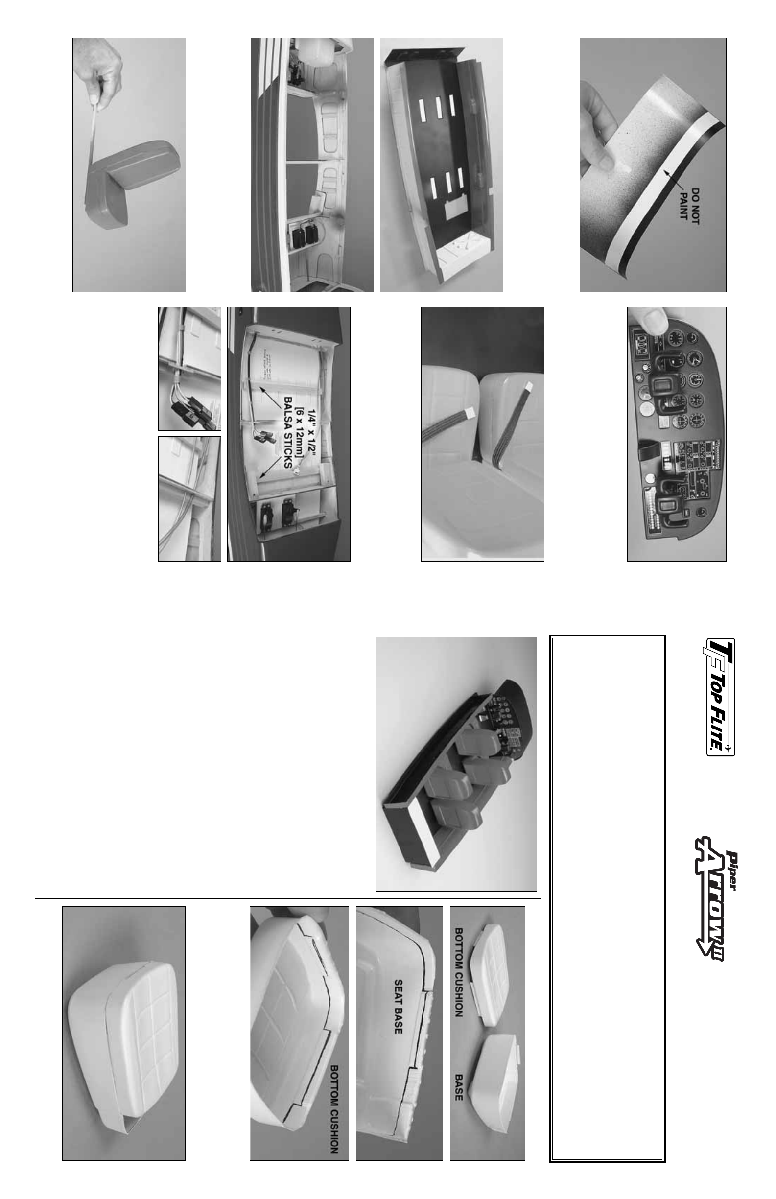
MAKE THE SEA TS
❏ 1. Cut out one of the seat bases and one of the bottom
cushions. True the edges by sanding with medium-grit
sandpaper and a bar sander. Note: The molded-in cutlines
have been dra wn with an ink pen for illustration in the photo.
❏ 2. Use thin or medium CA to glue the bottom cushion to
the seat base.
❏ Elastic band
(for seat belts)
❏ Decal
❏ (2) 1/8" x 1-1/4"
[3 x 32mm] dowel
❏ Right and left
cockpit sides
❏ Instrument panel
❏ Floor
❏ Valence panel
❏ Cabin back
❏ (4) Seat base
❏ (4) Bottom cushion
❏ (4) Seat back
❏ (4) Back cushion
❏ (2) Steering Yokes
❏ (3) Small pin
❏ (3) Large pin
SCALE COCKPIT KIT – ASSEMBLY INSTRUCTIONS
Copyright © 2004Printed in USA – ARO6CIP01 for TOPQ8414
PAINT THE COCKPIT KIT
❏ 1. Use a strip of masking tape to cover the inside of the
valence panel 3/8" [9.5mm] from the aft edge so it will not
get painted—this will allow for secure gluing to the
instrument panel.P aint the outside and inside of the valence
panel. Flat black is suggested.
❏ 2. Use masking tape to cover the indentations in the cockpit
floor where the seats will be glued down, then paint the cockpit
floor and sides. Also paint the formers in the fuselage that will
not be totally concealed by the cockpit sides.
❏ 3. Paint the seats. Use a drop of medium CA to
temporarily tack glue a balsa stick to each seat bottom.Hold
the stick and rotate the seat while painting.
FINAL ASSEMBLY
❏ 1. Cut out and paint the control yokes.Drill 1/8" [3.2mm]
holes through the instrument panel for the dowels, then glue
in the dowels and glue on the yokes .Paint the dowels black.
❏ 2.Securely glue the instrument panel and the dash board
into the cabin top.
❏ 3.Use the included elastic material to make the seatbelts .
Wrap a piece of chrome MonoKote
®
trim sheet or foil around
the ends to simulate buckles.
❏ 4. Install the cockpit kit in the fuselage using the #2 screws.
❏ 5. Glue two 1/4" x 1/2" [6 x 12mm] balsa sticks to the
underside of the cockpit floor where shown.This will give the
floor a little more rigidity and hold it steady to reduce
vibration. Guide the ser vo wires and air lines past former 3
so they can be connected to the wires and lines coming
from the wing.
❏ 6.The large and small pins may be used as you prefer to
simulate any control knobs or sticks seen in photos you
have of the full size cockpit.
Thank you for purchasing the cockpit kit for the Top Flite
®
Piper Arrow II. Even though the cockpit kit is somewhat
concealed under the completed and painted cabin top, you will still be surprised and pleased by how much more realism
and “life” the completed cockpit kit will bring to your Arrow. The same as the airplane kit, the level of detail that can be
achieved is up to you. Simply painting and installing the cockpit kit will achieve a good scale effect. Or, you could go “all
out” and add as many details and features as you can see in a real Piper Arrow cockpit.
Caution: Do not paint the cockpit kit parts with Top Flite LustreKote
®
.The cockpit is vacuum-formed from styrene plastic
which will be deformed by LustreKote. We found that Testors enamel paint works well for this type of plastic.Testors is
not fuelproof, but this should not be a problem as the components of the cockpit should not come into contact with fuel.
Page 2
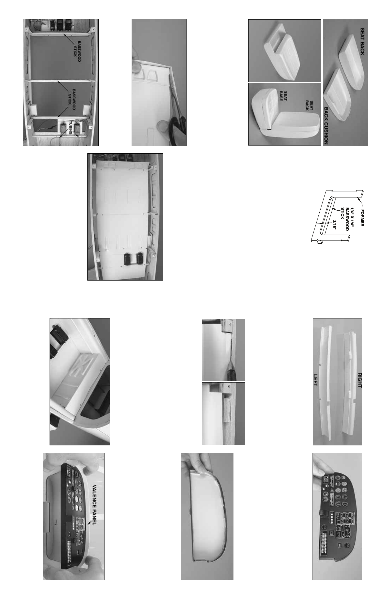
❏ 3. Cut out a seat back and a back cushion. Glue the two
pieces together.
❏ 4.Glue the completed seat back to the completed seat base.
❏ 5. Make three more seats the same way—hey, aren’t you
glad it’s not a 747?
INST ALL THE FLOOR
❏ 1. Use curved-tip plastic-cutting scissors to cut out the
cockpit floor. After cutting, the floor should be a flat sheet
with no lip around the edges.True the edges of the cockpit
floor by sanding.
❏ 2. Glue three 1/4" x 1/4" [6 x 6mm] basswood sticks (not
supplied) across the cross member portion of formers F3,
F4 and F5 as shown.Note that the top edge of each stick is
3/16" [5mm] above the top edge of each cross member.
❏ 3. Glue pieces of leftover 3/16" [5mm] pushrod tubing to
the aft edge of the aft servo rail to guide the air line coming
from the air tank.
❏ 4. As indicated in the instruction manual for the Arrow
airplane kit, cut notches in formers F3, 4 and 5 for the servo
wires and the air lines. Also round the top of former F4 to
accommodate the cockpit sides.
❏ 5. Bend the cockpit floor upward at the molded in scribe
line, but use care not to break it off.Reinforce both sides of
the seam with thin CA.
❏ 6. Test fit the cockpit floor into the fuselage. Cut the floor
where necessary to accommodate the formers and servos.
When in position, the front of the floor should be even with
the front of former F3.Drill 1/16" [1.6mm] holes through floor
and the 1/4" x 1/4" [6 x 6mm] sticks you glued to the f ormers
for fastening the cockpit floor with screws. Also drill holes in
aft servo rail. Install a #2 x 3/8" [9.5mm] screw into each
hole as you go.Some holes will have to be drilled from the
bottom of the sticks and up through the floor. Avoid drilling
holes where the screws will interfere with the cockpit sides
or seats.
INSTALL THE SIDES AND BACK
❏ 1. Cut out the left and right cockpit sides. True the
edges with a bar sander.
❏ 2. Test fit one, then the other cockpit side into the
fuselage.Widen the notches as necessary to accommodate
any formers or the canopy mounting blocks. The bottom
edges of the cockpit sides should rest on the cockpit floor.
❏ 3. Once any necessary adjustments have been made to
get the cockpit sides to fit, use thin CA to glue both sides to
the floor.
❏ 4. Use a ballpoint pen to mark the right main fuselage
stringer in three locations along the front, back and middle
of the top of the cockpit side.
❏ 5. Glue three 1/4" x 1/4" x 1" [6 x 6 x 25mm] hardwood
sticks to the stringer 1/64" [.5mm] below each line.
Note: The top of the cockpit sides must rest approximately
3/32" [2.4mm] below the top edge of the fuselage main
stringers. This will provide clearance between the screw
heads and the canopy frame.
❏ 6.Repeat the previous two steps for the left side of the coc kpit.
❏ 7. Drill 1/16" [1.6mm] holes through the top of the cockpit
sides into the hardwood sticks. Temporarily mount the
cockpit sides with six #2 x 3/8" [9.5mm] screws.
❏ 8. Cut out the cabin back. Test fit, then glue the aft edge
of the cockpit floor to the top of the lip on the bottom of the
cabin back. The same as was done for the sides, glue
hardwood sticks to former F6, then drill two more holes and
temporarily screw the back into position.
FIT THE INSTRUMENT P ANEL
❏ 1. Cut out the instrument panel—there should be an
approximately 1/8" [3mm] lip all the way around.
❏ 2. Attach the instrumentation decals using one of the
following two methods:
A) Paint the instrument panel, then cut out each instrument
from the decal sheet and stick it to the front of the panel.
B) Use a hobby knife and a rotary tool to cut all of the
instruments from the panel. Tr ue any straight edges with
a small hobby file. True circular holes with a piece of
sandpaper wrapped around a dowel or a brass tube.
Paint the instrument panel. After the paint dries, attach
the decal sheet, intact, to a plastic sheet. Cut out the
sheet, then glue it to the back of the instrument panel.
Use small balsa sticks to securely hold the sheet to the
back of the panel.
❏ 3. Cut out the valence panel. Test fit the valence panel
and the instrument panel inside the cabin top. Make
adjustments for a good fit, but do not glue it into the cabin
top until instructed to do so.
2 3
 Loading...