

Page 1
PARTS LIST
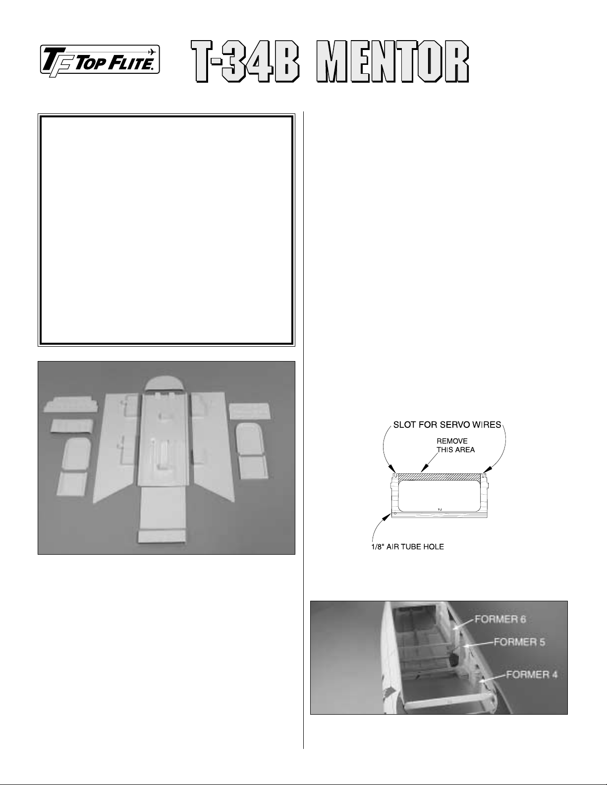
These are the parts included in this kit.
❏ T349CIPL01–Cockpit Floor
❏ T349CIPL02L–Left Sidewall
❏ T349CIPL02R–Right Sidewall
❏ T349CIPL03–Front and Rear Instrument Panel
❏ T349CIPL04–Seat Back and Bottom
❏ T349CIPL05–Center Glare Shield
❏ T349CIPL06–Glare Shield
❏ T349CIPL07–Rear Cockpit Wall
❏ T349CIPL08–Clear Plastic for Instrument Panel
❏ EXTGF25–Control Stick Dowel
❏ TAPE001–Black Elastic
❏ #17 White Head Pin
❏ #28 White Head Pin
❏ T349CPD01–Instrument Panel Decal
SUGGESTED TOOLS & SUPPLIES
❏
Curved-tip scissors suitable for cutting plastic (HCAR0667)
❏ Hobby knife and #11 blade
❏ Sandpaper and sanding tools
❏ Airbrush (if preferred)
❏ Paint brushes
❏ Paint (acrylic or enamel recommended)
❏ Clear RTV silicone or Shoe Goo
™
❏ Thin or medium CA
❏
Sheet of leftover 1/16" [1.6mm] or 3/32" [2.4mm]
balsa
GETTING STARTED
Assembling and installing your scale cockpit interior will probably
require minor adjustments and “tweaking” to fit your particular model.
This is because of variations in building technique, parts alignment and
glue fillets that may interfere with proper positioning of the parts.A little
patience is all that is required to obtain a good looking installation.Trim
parts a little at a time, checking the fit after each adjustment.
Remember,
you can always remove material, but it’s hard to put it back on.
❏ 1. Star t by trimming all parts to the embossed “trim lines.” Use a
hobby knife or scissors to “rough cut” the par ts. Then, sand the parts
with a sanding block to straighten the edges. You can evenly sand the
edges by simply taping a sheet of 220-grit sandpaper to your
workbench. Then, work the part in a circular motion while pressing
down gently.
Note: Save all scraps of smooth plastic in case you need them
later.
❏ 2. Before fitting any parts in the fuselage cavity, you will first need
to modify some of the formers.You will need to cut and remove the top
portion of formers F4, F5 and F6 that extend the width of the fuselage.
Note: We suggest that you first “dry fit” the parts into the cavity of the
fuselage. This will allow you to adjust the parts as needed, and
become familiar with the installation.
Thank you for purchasing a Top Flite®T-34 Mentor scale
cockpit interior. The parts in this kit represent an interior
modeled from drawings and photos of a full-size T-34. Not all
T-34’s have the exact same cockpit layout so, if necessary,
modifications could be made to this kit to make it exactly like
the one in your documentation. If precision authenticity is not
a priority, simply follow these instructions to end up with a
scale-looking cockpit interior that will really put the finishing
touches on your model. The parts in this kit must be painted
with a paint that is compatible with styrene (Top Flite
LustreKote
®
is not suitable for styrene). Since the cockpit is
inside the model, fuelproof paint is not necessary. Acrylic
paints found in craft stores can be purchased in a wide variety
of colors and in small containers. Small details such as
switches, knobs, dials, etc. can be applied with a paint brush,
but, if possible, the base coat should be applied with an
airbrush for the best results.
Replacement parts may be ordered as listed below through
your hobby shop , or online at:
www.top-flite .com.
For
accuracy, be
certain to include the par t numbers when ordering.
SCALE COCKPIT KIT – ASSEMBLY INSTRUCTIONS
Page 2
❏3. Install the parts in this order :
A. Cockpit floor
B. Front instrument panel
C. Left side wall
D. Right side wall
E. Rear wall
F. Rear wall top
G. Rear instrument panel
H. Rear former of front cockpit
I. Rear glare shield
J. Front glare shield
K. Front and rear seats
❏4.After you have finished dry fitting and trimming the parts, it is
time
to paint and detail your cockpit kit. Before painting,
thoroughly clean
the parts with rubbing alcohol, and then allow them to dry completely.
Paint all the parts with the base color of your choice.The prototype of
ours was painted all gray. The throttle quadrants,
sidewall accessories
and the glare shields were painted black.
Paint the lightest colors first,
and then, detail the cockpit to your liking.
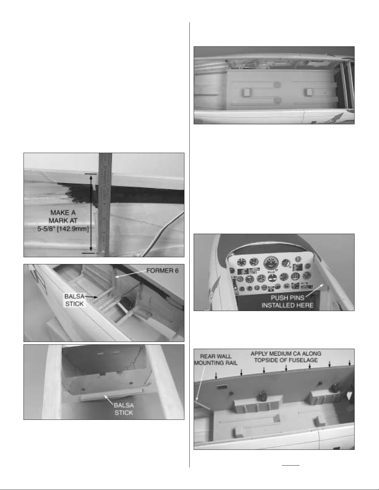
❏5.Now that all your cockpit parts are painted and detailed, let’s start
the installation.Measure from the top edge of the fuselage down 5-5/8"
[142.9mm] at former 6 and former 3. Make marks on the formers on
both sides of the fuselage at that distance.Glue the balsa sticks across
the bottom of former 6 and former 3, even with the two marks. This
provides a gluing surface and allows the floor to be level inside the
fuselage.
Note: The black paint in the previous photos was applied before the
cockpit kit was installed.This was used to dress up the cockpit area for
prototype pictures.
❏ 6. Apply a bead of medium CA along the balsa sticks that were
installed earlier in step 4.Install the cockpit floor, lining up the front with
the front edge of former 3.
❏
7. Before you install the front and rear instrument panels, you
must
decide on how you want to install the gauges from the decal sheet.
A. You can apply the decal sheet to the front of the
instrument
panels without cutting out the individual
gauges.
B. You can cut out the individual gauge locations on the
instrument panel, attach the clear sheet of plastic to the back of the
instrument panel, and then cut out each gauge from the decal sheet.
After the gauges have been cut out of the decal sheet, you apply them
to the backside of the clear plastic with regular Scotch
®
tape. This
process will be time consuming; however, when finished, your
instrument
panel will look more realistic.
❏8.Install the completed front instrument panel against former 3.You
can either glue the instrument panel to the former, or use
pushpins to
hold the lower sides and then glue the top to former
3a.
Note: The pushpins will be hidden after the cockpit walls are installed.
❏9.Apply a bead of medium CA to the topside of the fuselage. Install
the left sidewall against the topside. Do not
glue the bottom of the
2
Page 3

sidewall to the floor at this time.Once the rear wall has been glued in
place to each sidewall, then you can wick some thin CA under the
bottom of the sidewalls, which will attach the floor to the sidewalls.
❏ 10. Install the right sidewall in the same manner that you installed
the left sidewall in step 9.
❏11. Located at the rear of the sidewalls are two angled rails.These
are the gluing surfaces for the rear wall.Apply a bead of medium CA
to each rail and install the rear wall.
❏ 12. Use two pieces of masking tape to set the rear wall top into
position. Use thin CA to glue the rear wall top to the sides of the
fuselage, and to the top of the rear wall.
❏ 13. After you have finished applying the gauges to the rear
instrument panel, attach a leftover piece of balsa (not included) across
the back of the instrument panel for strength. Make a mark 9-1/8"
[232.2mm] from former F3 on both sides of the fuselage. This will be
the location of the rear instrument panel.
❏14.Trim the rear instrument panel to the shape shown in the above
photo.Install the rear instrument panel at the marks you made in step
13. Place the rear glare shield on top of the rear instrument panel to
determine how much of the top is raised above the fuselage sides.
Once the instrument panel is in place, remove the glare shield and
glue the rear instrument panel in position.
❏ 15. Before installing the rear former of the front cockpit, glue the
rear glare shield to the former. This will make it easier to determine
where the former should go.
3
Page 4

❏ 16. Install the former and the glare shield, with the glare shield
overhanging the top of the rear instrument panel by 1/8" [3.2mm].Use
thin CA to glue the rear former to the sidewalls, and the glare shield to
the inside of the fuselage rails.
❏ 17. Install the front glare shield, with it overhanging the front
instrument panel by 1/8" [3.2mm].
❏ 18. Glue the seat back to the seat bottom as shown in the three
previous photos.Before installing the seats you must remove the paint
from the seat mounts on the floor.This will allow the glue to properly
adhere the seat to the mount.The seat belts are made from the black
elastic included in this kit, and the buckles are made from a chrome
trim sheet (not included). The seat belts are glued to the rear of the
seat, and to the bottom of the seat. Install both of the seats into the
cockpit with medium CA.
When you take your T-34B Mentor to the field, tr y to be gracious
in accepting all the praise you will undoubtedly receive. Good
Luck and Happy Flying!
Copyright © 2002Printed in USA – T349CIP01 for TOPQ8413
 Loading...