

Page 1
PARTS LIST
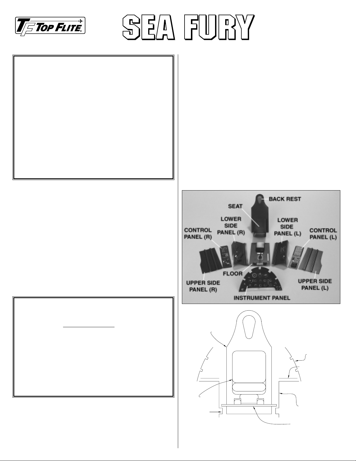
These are the parts included in this kit.
❏ Instrument panel
❏ Upper side panels (L & R)
❏ Lower side panels (L & R)
❏ Floor
❏ Back rest
❏ Control panels (L & R)
❏ Seat
❏ Instrument panel decal
❏ Details package (pins, elastic strap for seat belt,
dowel for control stick)
SUGGESTED TOOLS & SUPPLIES
❏ Curved-tip scissors suitable for cutting plastic
(HCAR0667)
❏ Hobby knife and #11 blade
❏ Sandpaper and sanding tools
❏ Airbrush (if preferred)
❏ Paint brushes
❏ Paint (acrylic or enamel recommended)
❏ Clear RTV silicone or Shoe Goo
❏ Thick or medium CA
❏ Sheet of leftover 1/16" [1.6mm] or 3/32" [2.4mm]
balsa
ASSEMBLY
Note: After cutting out the parts when instructed to do so,
true the edges with a
sanding block with 80-grit sandpaper.
Test fit each part in the model, so that the next part can be
fit to it.
Refer to the sketch and photo while assembling and
installing the cockpit kit.
❏ 1.
Cut out the instrument panel. Use a hobby knife with
a #11 blade or a rotary tool with a cutting bit to cut out the
SCALE COCKPIT KIT – ASSEMBLY INSTRUCTIONS
Thank you for purchasing a Top Flite®Sea Fury scale cockpit
interior. The parts in this kit represent an interior from
drawings and photos of a full-size Sea Fury. Not all Sea
Fury’s have the exact same cockpit layout so, if necessary,
modifications could be made to this kit to make it exactly like
the one in your documentation.If precision authenticity is not
a priority, simply follow these instructions to end up with a
scale-looking cockpit interior that will really put the finishing
touches on your model.The parts in this kit must be painted
with a paint that is compatible with styrene (Top Flite
LustreKote®is not suitable for styrene). Since the cockpit is
inside the model, fuelproof paint is not necessary. Acrylic
paints found in craft stores can be purchased in a wide
variety of colors and in small containers. Small details such
as switches, knobs, dials, etc. can be applied with a paint
brush, but, if possible, the main coat should be applied with
an airbrush for the best results.
Replacement parts may be ordered as listed below
through your hobby shop, through Product Support
(telephone: 217-398-8970, fax: 217-398-7721) or
online at: www.top-flite.com. For accuracy, be
certain to include the part numbers when ordering.
❏ SEA6CK01 Left upper side panel, left lower side
panel, seat
❏ SEA6CK02 Instrument panel, floor, back rest
❏ SEA6CK03 Right upper side panel, right lower side
panel, L & R control panels
❏ SEA6CKP02 Decal
❏ TAPE002 Elastic strap
BACK REST
SEAT
LEDGE
(INSTRUMENT PANEL NOT SHOWN)
UPPER SIDE PANEL
CONTROL PANEL
LOWER SIDE PANEL
FLOOR
Page 2

holes in the instrument panel for the gauges on the decal
sheet, but leave par t of the small ridge around each hole to
provide depth. Test fit and trim the instrument panel to fit
former F-6A in the cockpit. Trim the notches in the
instrument panel as necessary to accommodate the
stringers in the fuse.
❏
2. Cut out, then test fit the left and right upper side
panels. Trim the upper, aft edge of the panels even with the
edges of the opening in the cockpit.Note how the molded-in
stringers nearest the top of the side panels fit over the actual
stringers in the fuse.
❏
3.Test fit the left and right lower side panels. Note the
“ledge” near the bottom of the side panels intended to
support the cockpit floor.
❏
4.T rim the floor to fit between the lower side panels.Glue
a 1/16" [1.6mm] or 3/32" [2.4mm] balsa sheet (not included)
to the bottom of the cockpit floor to increase its rigidity.
❏
5. Glue a 1/16" [1.6mm] balsa sheet (not included) to the
back of back rest. Cut out the back rest, then fit it
into the
fuse and temporarily hold it in position with T-
pins.
❏
6. Cut out, then trim the left and right control panels to
fit on top of the lower side panels as shown in the sketch
(see step 1).
❏ 7. If installing the seat, cut out the seat and
temporarily
position it inside the cockpit. Note: The seat is not
necessary if installing a pilot. Without the seat, the pilot can
be glued into position more securely. The absence of the
seat will not be noticed with the pilot in the cockpit.
❏
8. Test fit the pilot (not included) in the fuse. Position the
canopy on the fuse to be certain there is clearance for the
pilot’s head.Make adjustments where necessary.
❏
9.All of the parts of the cockpit should now be in position.
Make adjustments where required so all the parts fit
together.Note any corners or other areas in the fuse that the
cockpit kit does not fully conceal. Paint these areas the
same color as the base-coat of the cockpit parts.
❏
10. Wash the par ts in warm, soapy water, then roughen
with 400-grit sandpaper so paint will adhere.Spray paint the
parts (flat black was used on the prototype model) and allow
to dry.
❏
11. Apply the instrument panel decal to a piece of thin
plastic or cardstock (such as from a cereal box). Trim the
cardstock to fit the back of the instrument panel. Glue the
instrument panel decal to the back of the instrument panel
using clear RTV silicone or Shoe Goo.
❏
12. Apply the rest of the decals to the control panels.
Using the photo on this instruction sheet or your scale
documentation as a guide, paint whatever details you
choose to add such as switches, dials, latches , etc.The pins
supplied with this kit may be used to simulate v arious control
sticks and levers such as the throttle,
etc. Make the flight
control stick using the dowel
provided. A hand grip can be
made by applying automotive filler to the dowel. Allow to
harden, then carve to shape.
❏
13. Install the parts in the fuse. Securely glue them into
position with medium or thick CA.
❏
14. Glue the pilot into position using Shoo Goo or clear
RTV silicone. For the best adhesion, scrape the paint from
the pilot and cockpit where they contact each other and are
to be glued.
❏
15. Make certain the pilot and all the parts of the cockpit
kit are securely glued in place before permanently gluing on
the canopy.
If you have questions or comments write or call:
Top Flite Models
P.O.Box 788
Urbana, IL 61803
(217) 398-8970
e-mail:
prodductsupport@top-flite.com
Copyright © 2001
Printed in USA – SEA6CIP01 for TOPQ8412
 Loading...