

Page 1
R
USS
U
E
E
R
’’SS M
M
A
A
N
N
U
U
ALL
A
Page 2

Table of Contents
System Components.......................................................................................................2
Mounting the VisiChart....................................................................................................2
VisiChart Features...........................................................................................................7
Turning the VisiChart On.................................................................................................8
Turning the VisiChart Off.................................................................................................8
Configuring VisiChart ......................................................................................................9
VisiChart Remote Diagram............................................................................................12
Using the VisiChart........................................................................................................13
Troubleshooting Procedures.........................................................................................14
Hardware Specifications................................................................................................15
Page 3

System Components
• VisiChart all-in-one system
• Remote Control
• Infrared Detector
• USB Keyboard
• USB Mouse
• Power cable
• Wall Mount Adapter Plate
• Wall Mounting Bracket & Hardware
• Mouse Pad
• Users manual
• Two AAA Batteries
Mounting the VisiChart
Direct View – When mounting the VisiChart directly in front of the patient, the center of
the monitor should be approximately 54” off the floor and centered in front of the patient
sitting in the exam chair. Recommended minimum direct view distance from patient is 3
meters. (Approximately 10 feet)
Mirrored View – When mounting the VisiChart behind the patient and using a mirror to
increase the total refraction distance, the center of the VisiChart should be located 78”
off the floor and 18” from the center of the chair, opposite the stand, so that the near-rod
does not interfere with the image presented in the mirror.
Electrical: It is recommended that a standard electrical outlet is installed behind the
VisiChart for best appearance, however the VisiChart can be plugged into any outlet
within five feet of the mounting location.
Remote Control Sensor: Plug the USB connector into any USB port on the side of the
VisiChart. Attach the sensor to the VisiChart with the enclosed Velcro pad to any
location facing into the exam room. Bundle and conceal the cable behind the VisiChart.
Note: The use of fluorescent lighting in the exam room will decrease the sensitivity of
the remote control. Incandescent lighting during VisiChart use is recommended.
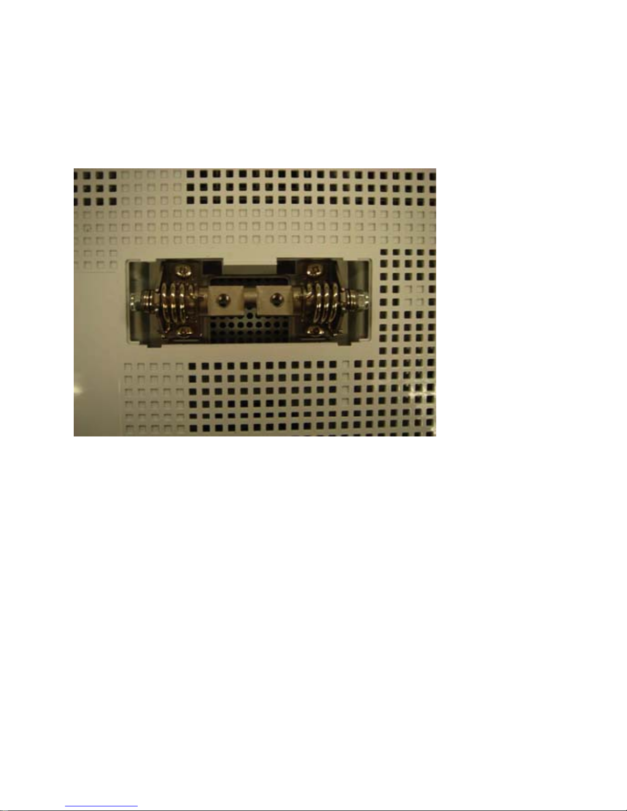
Wall mounting the VisiChart
1. Remove the silver plastic cover on the rear of the VisiChart to expose the screws
which attach the table mount base. (Figure 1)
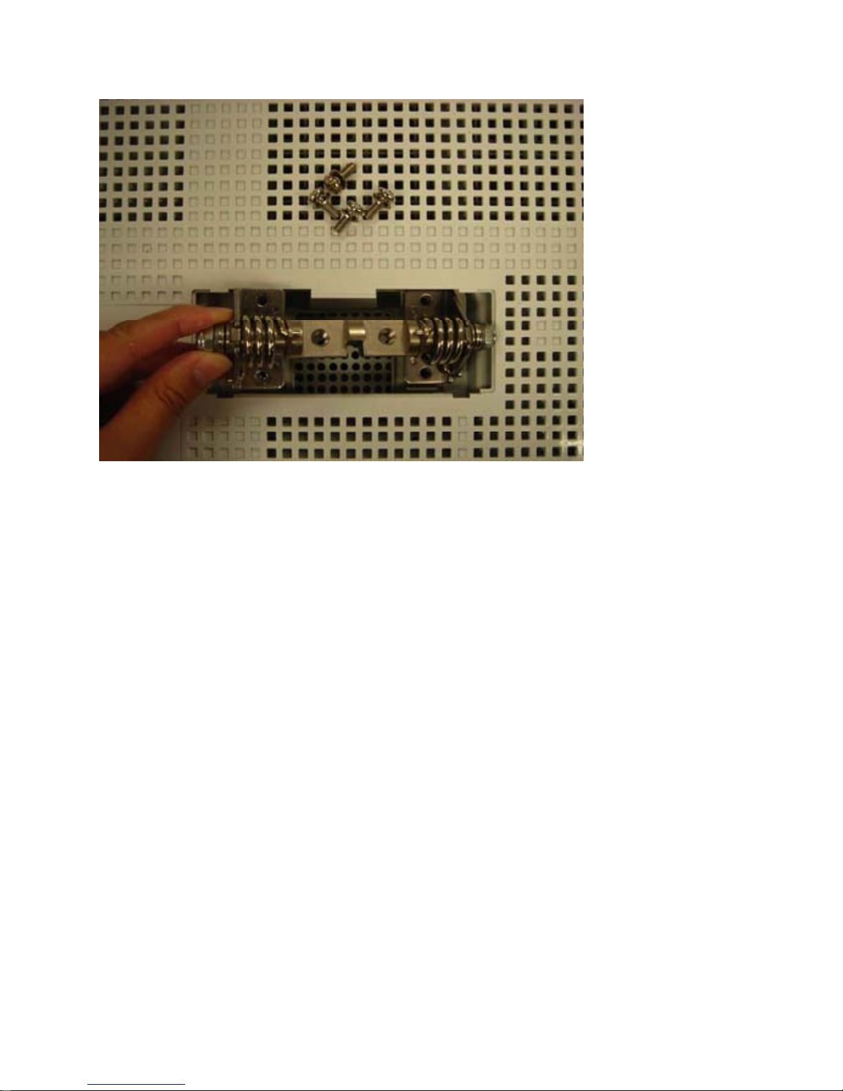
2. Loosen the four M4 Phillips screws and remove the hinge and base. (Figure 2)
3. Using the M4 screws, attach the wall mount adapter plate. (Figure 3)
Rev. C, 06/07
2
Page 4
4. Tighten the four screws securely. (Figure 4)
5. Installation of the wall mount adapter plate is now complete. (Figure 5)
Note: For the wall mount bracket installation, a qualified installer should follow
the instructions which are included with the bracket.
Figure 1
Figure 2
Rev. C, 06/07
3
Page 5
Rev. C, 06/07
4
Page 6
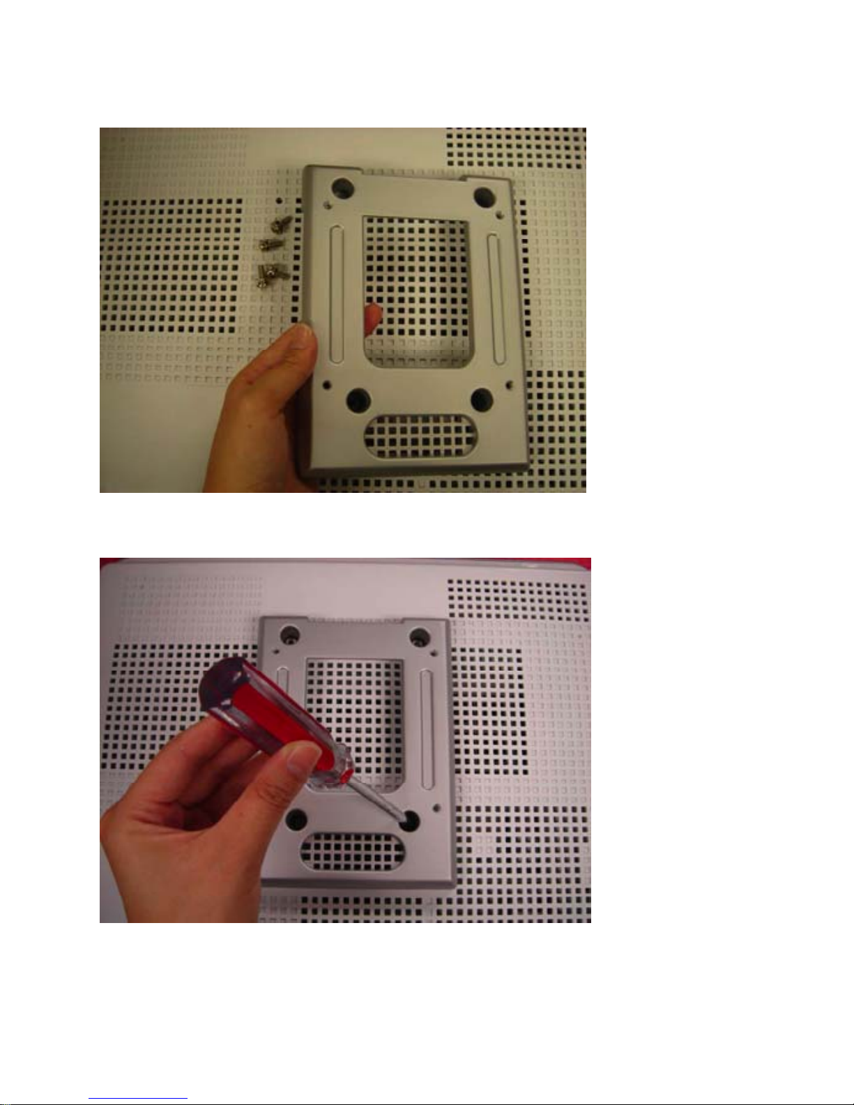
Figure 3
Figure 4
Rev. C, 06/07
5
Page 7

Figure 5
Rev. C, 06/07
6
Page 8

VisiChart Features
Charts
• Snellen
• HOTV
• Numbers
• Allen Pictures
• Tumbling E's
• ETDRS Charts
• Contrast
Isolations
• Horizontal Line
• Vertical Line
• Single Character
• Three Lines Same Size
• Pointer for Horizontal and Vertical Lines
Additional Features
• Customizable Test Sequence
• Red/Green Duochrome available for all charts
• White Optotypes on Black Background available for all charts
• Worth 4 Dot Test
• Single Fixation Dot
• Full Randomization of all charts
• Black Screen
• Corner Size Indicator
• Astigmatic Dials and Fixation Disparity
• Cycle Timer for hands-free randomization
• Fixation Animation
• Size buttons for 20/10 – 20/400
Rev. C, 06/07
7
Page 9

Turning the VisiChart On
1. To turn the VisiChart on and begin testing press the power switch on the front of
the system
2. VisiChart will automatically launch to the Snellen Chart
Turning the VisiChart Off
1. Exit VisiChart by pressing ALT + BLACK on the remote control
2. VisiChart will exit to Microsoft Windows
3. Press the power switch on the front of the system and the system will power off
Rev. C, 06/07
8
Page 10

Configuring VisiChart
1. Plug the keyboard and mouse into the VisiChart before starting the system.
2. VisiChart will launch.
3. Press “?” on the keyboard to enter the configuration screens.
4. Set the distance, measuring from the bridge of the nose to the VisiChart. With a
mirrored room, measure from nose to mirror and the mirror to the VisiChart,
adding these numbers.
5. Set Direct or Mirror.
6. Click Next.
7. Set the 10 cm by 10 cm square.
Rev. C, 06/07
9
Page 11

8. Click Next.
9. Set the Black Screen Timer if desired, the display will go to a black screen in
the set number of minutes.
10. Set the Random Letter Timer if desired.
11. Set whether to Show Screen Size Note this can be toggled with ALT + W4D.
12. Set whether to use a Green or Blue Worth 4 Dot.
13. Click Next.
14. Optional – Click Next to continue without modifying the default chart options.
15. The Default Chart can be adjusted, changing the number of rows and number of
optotypes shown per line.
16. Check Always Random to never show the default chart.
17. Using the Select Opto Size here for settings choose a line of the chart.
18. The Number of lines displayed and Number of Characters per Line as well
as the Default Characters can now be set.
19. Repeat 17 and 18 for each line.
20. Click Next to continue.
21. Optional Test Sequence (Protocol) Setup – click Next if a customized
sequence is not needed.
Rev. C, 06/07
10
Page 12

22. Choose a Size, Chart and Function using the drop-down controls and click Add.
23. Continue adding charts.
24. By clicking on the newly added row, use Move Up and Move Down to order the
list.
25. Use Delete to remove any item not needed.
26. When complete click Next.
27. The main calibration screen is again shown, click Done.
28. The VisiChart is now ready for use!
29. The Snellen Chart will be displayed.
Rev. C, 06/07
11
Page 13

VisiChart Remote Diagram
Rev. C, 06/07
12
Page 14

Using the VisiChart
VisiChart is controlled with the remote control. The chart below provides information on
each function
Button Function
ALT Provides access to lesser used functions
HOTV HOTV Chart
W4D Worth 4 Dot Test
Dot Fixation Dot
LTR Snellen Letter Chart
NUM Number Chart
E Tumbling E Chart
PIC Allen Pictures Chart
Round L & R Randomize the current chart
Round U & D Increase/Decrease chart size
RG Red/Green Duochrome Chart
CYC Randomize the chart every four seconds
MISC Custom Chart Sequence
HLINE Horizontal Line
VLINE Vertical Line descending in size
3LINE Three lines of same size
ETDRS ETDRS Charts
SGL Single Optotype
BLACK Black Screen
Up/Down Increase/Decrease Chart Size
Arrow Add a pointer to the Horizontal or Vertical Line – use up/down to move
400 – 10 Directly set the top line of the chart or the horizontal line to be that size
NOTE: For ALT functions, the ALT key should be pressed and released.
ALT - MISC Astigmatic Dials and Fixation Disparity
ALT - BLACK Exit VisiChart
ALT - W4D Toggle the Corner Size Indicator
ALT - HLINE Reverse the chart for white optotypes on black screen
ALT - RG Contrast Line – Use Up/Down to increase/decrease contrast percentage
ALT - HOTV Fixation Animation
Rev. C, 06/07
13
Page 15
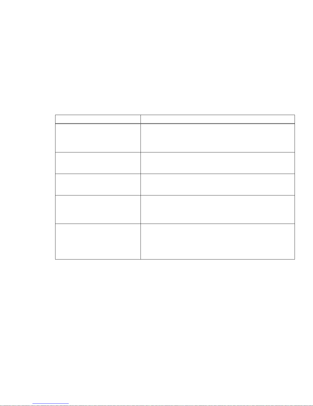
Troubleshooting Procedures
The VisiChart troubleshooting section summarizes some common issues and
possible areas to check to resolve the problem. If the matter is related to
VisiChart operation, please refer to other sections of this User’s Manual for
detailed information on the operation, adjustment, and features of the VisiChart.
If the issue cannot be resolved by using the trouble-shooting guide, a Topcon
authorized customer service technician should be called upon for assistance.
Issue/Problem Possible Solution
1. VisiChart does nothing
(no power light or function)
2. VisiChart is ON, but does
nothing (Black Screen, no
function from remote control)
3. VisiChart is ON and
displays a chart, but does not
respond to remote control.
4. VisiChart begins to start,
but an error during start-up
occurs before displaying a
chart.
5. VisiChart begins to start,
but a “keyboard not found”
error during start-up occurs
before displaying a chart.
1a. Check to see if the VisiChart is connected to the
AC power source, and that the power source is
live.
1c. Check cabling for damage.
2a. Unplug and re-plug the IR sensor.
2b. Check remote control batteries.
2c. Press power button to restart system.
3a. Unplug and re-plug in IR sensor.
3b. Check remote control batteries.
3c. Press power button to restart system.
4a. Press power button to restart system.
4b. Call Topcon customer service for assistance.
5a. Verify that the IR sensor is firmly plugged into a
USB port and restart the system by pressing the
power button.
5b. Call Topcon customer service for assistance.
Rev. C, 06/07
14
Page 16

Hardware Specifications
Operating System
Windows® XP
Processor
Intel Pentium 4
Chipset
i945g chipset
Dimensions/ Weight
16.1"W x 13.9"H x 3.78"D (w/o stand)
16.1"W x 17"H x 8.5"D (w/stand)
25.5 lb (w/stand)
21.6 lb (w/o stand)
Memory
512k DDR2 SDRAM
Video
Integrated Intel GMA graphics
Display
17" SXGA LCD panel, 1280 x 1024
Storage
80GB 2.5" hard drive, DVD/CD-RW combo drive
Network Interface
Integrated Intel 10/100/1000 Gbit Ethernet
Wireless LAN
802.11b,g wireless LAN
Audio
2-Channel High-Definition audio, integrated 2x speakers
Expansion Slots
Two Type II slots, or one Type III PCMCIA slot
I/O Ports
Two PS/2 ports (keyboard/mouse)
Four USB 2.0 ports (4x on chassis)
One serial port
One parallel port
One RJ45
One VGA
Audio ports (Mic-in, Line-in, Line-out)
Power
Input: AC/100~240V (50/60Hz) 4.0A
Certification
FCC, CE, UL
Rev. C, 06/07
15
Page 17

Topcon Medical Systems, Inc.
37 West Century Road
Paramus, NJ 07652
800-223-1130
www.topconmedical.com
Rev. C. 06/07
 Loading...