

Page 1
INSTRUCTION MANUAL
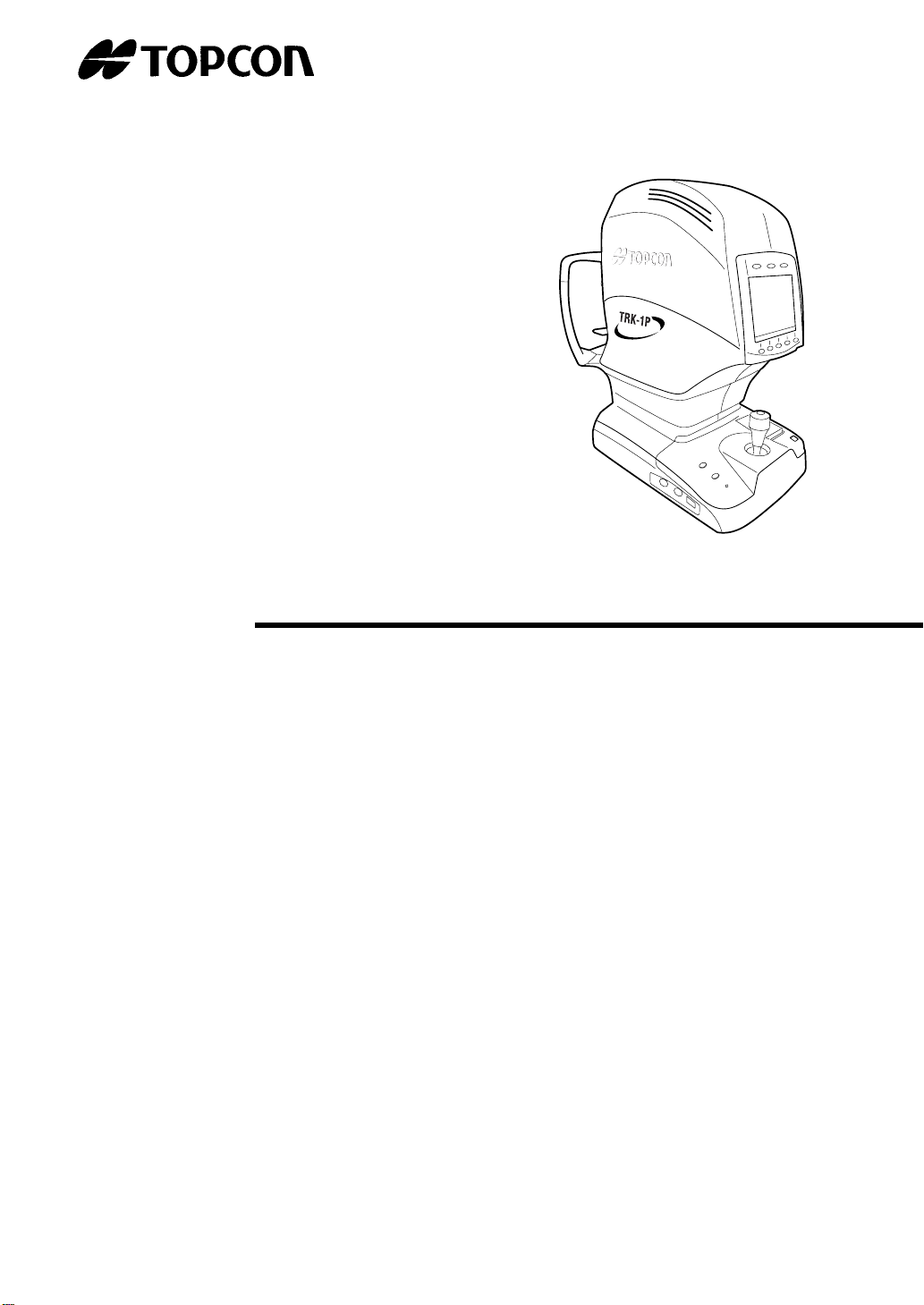
AUTO KERATO-REFRACTO-TONOMETER
TRK-1P
Page 2
INTRODUCTION
Thank you for purchasing the TOPCON Auto Kerato-refracto-tonometer TRK-1P.
This instrument has the following features:
• Exact measurement of refraction power, corneal curvature, intraocular pressure and
central corneal thickness by simple operations
• Softer air blow in measuring intraocular pressure
•
Auto alignment and auto start functions enabling quick measurement under best conditions
This text outlines the Auto Kerato-refracto-tonometer TRK-1P and describes basic operations, troubleshooting, checking, maintenance and cleaning.
To encourage the safe, efficient use of this instrument, carefully read "Displays for Safe
Use" and "Safety Precautions."
Also, keep this Instruction Manual in a convenient location for your future reference.
PRECAUTIONS
• This is a precision instrument, install/store it in a place with the following conditio ns: temperature (10 to 40
direct exposure to sunlight.
• To ensure smooth operation, install the in strument on a leveled st and free of vibrations. Also , do
not place any objects on the instrument.
• Before using the instrument, connect all cables correctly.
• Use the specified source voltage.
• When not in use, turn off the power and put the measuring win d ow lens ca p an d du st cove r on .
• To ensure the correct reading, do not mar the measuring window with finger prints, dust, etc.
Also, do not touch the measuring nozzle except during cleaning.
°C), humidity (30 to 75%) and atmospheric pressure (700 to 1060hPa). Avoid
[WARNING]
When operating the instrument, be not touch the patient's eye or nose.
[WARNING]
To prevent corneal damage, do not measure a patient with corneal disease or corneal surgery.
To prevent corneal damage, do not measure a patient's wearing a contact lens.
This symbol is applicable for EU member countries only.
To avoid potential negative consequences for the environment and possibly human
health, this instrument should be disposed of (i) for EU member countries - in
accordance with WEEE (Directive on Waste Electrical and Electronic Equipment),
or (ii) for all other countries, in accordance with local disposal and recycling laws.
1
Page 3

CAUTIONS ON USE
BASIC NOTES
Do not open the cover. For repair, ask our service engineer (to avoid electric shocks).
Keep the instrument in a dry place.
Do not open the cover. For repair, contact your authorized Topcon distributor.
When changing the fuse, turn off the power, and disconnect the power cable. Use the rated
fuse.
DISPOSAL
When disposing of the instrument, observe ordinances of the jurisdiction on disposal and
recycling.
WORKING ENVIRONMENT
Temperature: 10 to 40°C
Humidity: 30 to 75% (no dewing)
Atmospheric pressure:700 to 1060hPa
STORAGE, USAGE PERIOD AND OTHERS
1. INSTALLATION CONDITIONS (WITHOUT PACKAGE)
Temperature: 10 to 40°C
Humidity: 30 to 75% (no dewing)
Atmospheric pressure:700 to 1060hPa
2. STORAGE CONDITIONS
(1) Keep the instrument in a dry place free of dust, salt, sulfur, chemicals or gases.
(2) Keep the instrument in a place free of the effects of atmospheric pressure, temperature,
moisture, draft, sunshine, dust, salt and sulfur.
(3) Avoid storing the instrument on inclined surfaces and avoid shock and vibrations during
transport.
(4) Avoid places storing chemicals and generating gases.
3. NORMAL LIFE SPAN OF THE INSTRUMENT
Eight (8) years from delivery providing regular maintenance is performed (TOPCON data)
TRANSPORT AND STORAGE CONDITIONS (with package)
Temperature: -20°C to 50°C
Humidity: 10 to 95%
MAINTENANCE AND CHECKS
1.Regularly maintain and check the equipment and parts.
2.When resuming the use after a long storage time, verify that the instrument operates correctly and safely.
3.To ensure the correct reading, do not mar the measuring window with finger prints, dust,
etc.
4. If the measuring window is soiled, clean it following the "CLEANING THE MEASURING
WINDOW GLASS" instructions on page 156.
2
Page 4
DISPLAYS FOR SAFE USE
In order to encourage the safe use of the machine and prevent any danger to the operator and
others or damage to properties, important warnings are placed on the product and inserted in the
instruction manual.
We suggest that everyone understand the meaning of the following displays and icons before
reading the "Safety Precautions" and the main text.
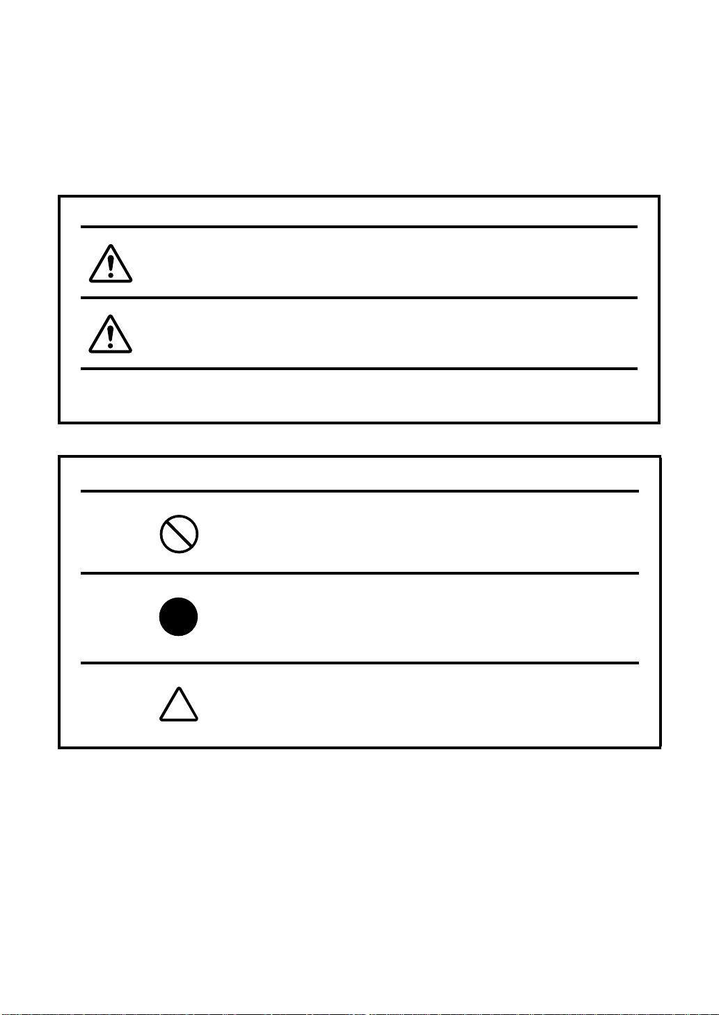
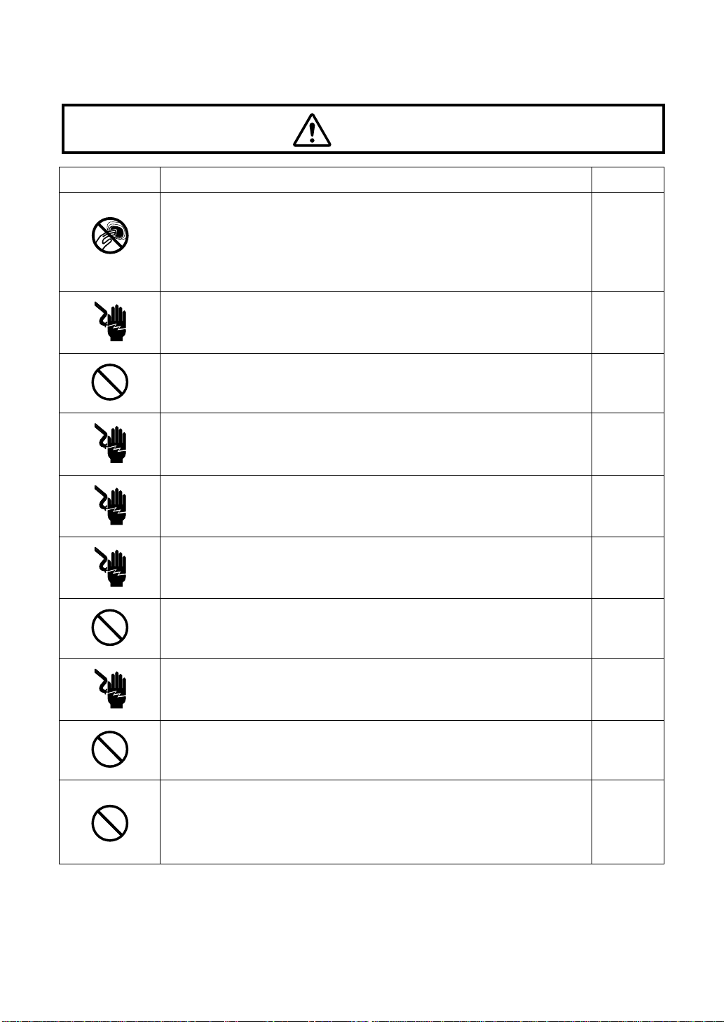
DISPLAY MEANING
Ignoring or disregarding this display may lead to
WARNING
CAUTION
• Injury refers to cuts, bruises, sprains, fractures, burn, electric shock, etc.
• Physical damage refers to extensive damage to buildings or equipment and furniture.
ICON MEANING
death or serious injury.
Ignoring or disregarding this display may lead to
personal injury or physical damage.
This icon indicates Prohibition.
Specific content is expressed with words and/or an
illustration near the icon.
This indicates Mandatory Action.
Specific content is expressed with words and/or an
illustration near the icon.
This indicates Caution.
Specific content is expressed with words and/or an
illustration near the icon.
3
Page 5
SAFETY PRECAUTIONS
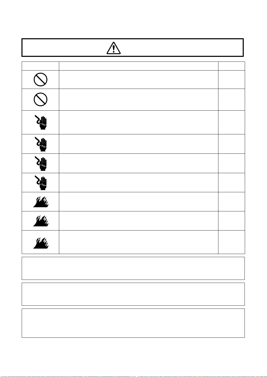
WARNING
Icon Description Page
To prevent corneal damage, do not measure a patient with corneal
disease or corneal surgery.
To prevent corneal damage, do not m easure a patient's wearing a
contact lens.
Tell the patient to remove the contact lens.
Do not open the cover. For repair, contact your authorized Topcon
distributor.
Keep the instrument in a dry place.
To avoid fire and electric shocks, keep the instrument in a dry
place.
To avoid fire and electric shocks in case of tumbling, do not place a
cup or vessel containing water/fluid near the instrument.
To avoid electric shocks, do not insert metal objects into the instrument body through the vent holes or gaps.
When changing the fuse, turn off the power, and disconnect the
power cord. Use the rated fuse.
To av oid fire and electric shocks by short circuiting, be sure to connect the instrument into a grounded outlet.
—
113
8
162
—
—
—
8
160
34
In case an abnormal condition such as smoke occurs, immediately
switch OFF the power and unplug the power cable. Contact your
dealer for repair.
WARNING : Handling the cord on this product or cords associated with accessories sold with
this product, will expose you to lead, a chemical known to the State of California to cause birth
detects or other reproductive harm. Wash hands after handling
This Product Contains Mercury in the backlighting of the LCD display. Prior to disposal remove
of otherwise ensure that this is dispose d of in accordance with Lo cal, State and Federal Laws.
This information is applicable in U.S.A only.
This Product Contains a CR Lithium Battery which contains Perchlorate Material-special handling may apply.
See http://www.dt s c.ca.gov/hazardouswaste/perchlorate/
Note; This is applicable to California. U.S.A only.
—
4
Page 6
CAUTION
Icon Description Page
8
To avoid injury in changing the measurement mode, do not place
fingers into the measuring opening.
* Inform the patient accordingly
90
96
109
To avoid injury, when moving the chinrest up/down, keep fingers
away from moving parts.
To avoid injury, do not install the instrument on a slope or on an
unstable place.
To avoid electrical shock, do not handle the power plug with wet fingers.
To avoid failure or potential injury, do not open the printer cover
while the printer is in operation.
To avoid potential injury in case of malfunction, including a paper
jam, be sure to shut off the power before attempting to repair it.
Never insert your fingers under the chinrest.
* Inform the patient of this, too.
Careless insertion of fingers may cause injury by pinching.
Do not use or apply any spray-type cleaner near the instrument.
If the cleaner remains inside the measuring nozzle, the patient's
eye may be injured during measurement.
8
33
34
86
159
86
159
98
113
161
When operating the instrument, be careful not to touch the p atient' s
eye or nose.
When moving the instrument, be sure to hold it at the base with two
persons. Carrying by one person may cause harm to his back or
injury by falling parts. Also, holding areas other than the base may
cause injury, as well as damage to the instrument.
8
33
5
Page 7

CAUTION
Icon Description Page
When setting an instrument on an instrument table, pay attention
not to injure the patient's fingers between the instrument and the
table.
33
To avoid potential injury, do not touch the printer body while the
printer is in operation or when replacing the printer paper.
Before starting measurement, be sure to confirm the measuring
screen (to avoid making the ocular pressure measurement to the
patient's eye wearing a contact lens.)
Before measuring, check if there is any foreign matter on and
around the measuring nozzle.
If any, it may enter and damage the patient's eye during the measurement.
Before measuring, set the safety stop to prevent the measuring
window glass from hitting the patient's eye.
Set it respectively for the right and left eyes.
Set the safety stop from the side face of the instrument.
Setting operations from other positions, where checking of the eye
position is not easy, may cause injury.
Clean the measuring window glas s, meas ur ing nozz le and the w indow glass inside the measuring nozzle using ethanol.
Other chemicals may cause damage to the patient's eye during
measurement.
86
159
101
106
119
126
110
114
114
156
157
6
This instrument has been tested (with 100/120/230V) and found to
comply with IEC60601-1-2: Ed.2.1: 2004.
This instrument may emit a radio frequency energy (within the standard) and cause an adverse effect on the devices located nearby.
When such effect is confirmed by the ON/OFF operation, a proper
treatment as to change the direction, use another outlet, etc. is recommended. If the problem remains unsolv ed , call yo ur deal er.
—
Page 8

USAGE AND MAINTENANCE
PURPOSE
This Auto kerato-refracto-tonometer "TRK-1P" is a precision electrical instrument for
medical use which must be used under instructions of a doctor.
USER MAINTENANCE
To maintain the safety and performance of the instrument, never attempt to do maintenance
on your own. Ask our service engineer for repair except for the items specified here which can
be maintained by the user. For details, follow the instructions.
CHANGING THE FUSE
The primary fuses for the main body may be changed by a non-trained service techn ician.
For details, refer to "REPLACING THE FUSE" on page 160.
CLEANING THE MEASURING WINDOW
The measuring window glass may be cleaned. For details, refer to "CLEANING THE MEASURING WINDOW GLASS" on page 156.
CLEANING THE MEASURING NOZZLE AND WINDOW INSIDE THE MEASURING NOZZLE
Regarding the measuring nozzle and the window glass surface inside the measuring nozzle,
cleaning is allowed.
For detail see "CLEANING THE NOZZLE AND CHAMBER GLASS INSIDE THE MEASURING NOZZLE"on page 157.
ESCAPE CLAUSE
• TOPCON shall not take any responsibility for damage due to fire, earthquakes, actions by a
third party or other accidents, or the negligence and misuse of the user and use under
unusual conditions.
• TOPCON shall not take any responsibility for damage derived from inability to use this
equipment, such as loss of business profits and suspension of business.
• TOPCON shall not take any responsibility for damage caused by operations other than
those described in this Instruction Manual.
• Diagnosis shall be made on the responsibility of the doctors, and TOPCON shall not take
any responsibility for the result of such diagnosis.
7
Page 9
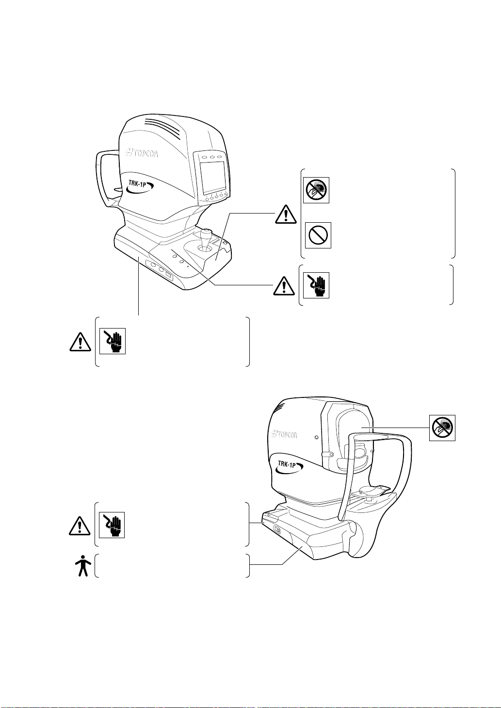
WARNING INDICATIONS AND POSITIONS
To ensure the safety, this machine provides warning displays.
Use the instrument correctly by observing the display instructions. If any of the following display labels are missing, contact your TOPCON dealer at the address listed on the back cover.
• Do not open the cover. For repair,
WAR NI NG
contact your authorized Topcon distributor.
Keep the instrument in a dry place.
• T o avoid inju ry in chang ing the mea surement mode, do not place fingers into the measuring opening.
* Inform the patient accordingly.
• When operating the instrument, be
careful not to touch the patient's eye
or nose.
CAUTION
• To avoid injury, when moving the
chinrest up/down, keep fingers away
from moving parts.
CAUTION
8
• When changing the fuse, turn off the
WARNING
power, and disconect the power
cord. Use the rated fuse.
Degree of protection against electric shock:
TYPE B EQUIPMENT
Page 10

CONTENT
INTRODUCTION ...................................................................................................1
DISPLAYS FOR SAFE USE..................................................................................3
SAFETY PRECAUTIONS......................................................................................4
USAGE AND MAINTENANCE ..............................................................................7
ESCAPE CLAUSE.................................................................................................7
WARNING INDICATIONS AND POSITIONS ........................................................8
COMPONENTS
COMPONENT NAMES.......... ... ... ... .... .................................................................12
COMPOSITION OF PARTS WHICH CONTACT THE HUMAN BODY........ ...... .12
CONTROL PANEL COMPONENTS (REF/KRT MODE).....................................13
CONTROL PANEL COMPONENTS (TONO/PACHO MODE) ............................16
MONITOR SCREEN COMPONENTS (REF/KRT MODE) ..................................19
MONITOR SCREEN COMPONENTS (TONO/PACHO MODE)..........................22
OTHER SCREEN DISPLAYS..............................................................................25
PRINTER OUTPUT .............................................................................................27
STANDARD ACCESSORIES....................................................... .......................32
PREPARATIONS
INSTALLING THE INSTRUMENT.......................................................................33
CONNECTING THE POWER CABLE...... ... ... .... ... ... ... .... ... ... ... .... ... ... ... ... .... .......34
CONNECTING EXTERNAL I/O TERMINALS .....................................................35
FUNCTION SETTINGS BY MEANS OF MENU.......................................................36
LIST OF MENUS................................ ... ... ... ... .... ... ... ...........................................36
INITIAL SETTING.............. .... ... ...........................................................................38
PREPARATION FOR INITIAL SETTING ......................................................38
RETURNING TO THE MEASUREMENT SCREEN......................................38
INITIAL SETTING..........................................................................................39
SETTING PRINTOUT....................................................................................49
ON-LINE SETTING (DATA COMMUNITATION)...........................................61
MENU SETTING..................................................................................................67
PREPARATION FOR MENU SETTING........................................................67
DISPLAYING THE MENU SCREEN .............................................................67
RETURNING TO THE MEASUREMENT SCREEN......................................68
MENU SCREEN UNDER FULLY AUTOMATIC MEASUREMENT MODE... 68
SETTING MENU (R/K)..................................................................................69
SEETING MENU (T/P) ..................................................................................81
SETTING THE PRINTER PAPER.......................................................................86
RESETTING FROM POWER SAVE STATUS ....................................................88
OPERATING THE CONTROL LEVER................................................................88
9
Page 11

BASIC OPERATIONS
CHANGING THE MEASUREMENT MODE .............................................................90
MEASUREMENT MODE............. ... .... ... ... ... ... .... .................................................90
TYPE OF MEASUREMENT TO BE DONE UNDER REF/KRT
MEASUREMENT MODE............. ... .... ... ... ... ... .... .................................................92
TYPE OF MEASUREMENT TO BE DONE UNDER TONO/PACHO
MEASUREMENT MODE............. ... .... ... ... ... ... .... .................................................93
CHOOSING THE EYE TO BE MEASURED........................................................94
WHEN MEASURING THE REFRACTORY POWER AND CORNEAL
CURVATURE RADIUS OF THE EYE.......................................................................96
PREPARATION BEFORE MEASUREMENT (REF/KRT MODE) . .......................96
TURN ON THE POWER ...............................................................................96
POSITIONING THE PATIENT............................................................ .... .......98
ADJUSTING MONITOR'S ANGLE................................................................99
MEASUREMENT UNDER AUTO MODE (REF/KRT MODE)............................100
MEASUREMENT UNDER MANUAL MODE (REF/KRT MODE).......................105
DISPLAYING MEASUREMENT VALUES (REF/KRT MODE) ..........................107
DELETING MEASUREMENT VALUES (REF/KRT MODE)..............................108
WHEN MEASURING THE OCULAR PRESSURE AND CORNEA
THICKNESS OF THE EYE.....................................................................................109
PREPARATIONS BEFORE MEASUREMENT (TONO/PACHO MODE) ..........109
TURN ON THE POWER .............................................................................109
CHECKING THE MEASURING NOZZLE ...................................................110
AIR CHECK.................................................................................................111
POSITIONING THE PATIENT............................................................ .... .....113
ADJUSTING MONITOR'S ANGLE..............................................................114
SETTING THE SAFETY STOP...................................................................114
MEASUREMENT UNDER AUTO MODE (TONO/PACHO MODE)...................117
MEASUREMENT UNDER MANUAL MODE (TONO/PACHO MODE)..............124
MEASURING THE CORNEA THICKNESS (TONO/PACHO MODE) ...............130
DISPLAYING MEASUREMENT VALUES (TONO/PACHO MODE)... ...... .... ... ..131
DELETING MEASUREMENT VALUES (TONO/PACHO MODE) .....................132
IN A CASE LIKE THIS ...........................................................................................133
TO STOP MEASUREMENT..............................................................................133
TO MEASURE THE RIGHT/LEFT EYE ONLY..................................................134
THE LIMIT ICON APPEARS AND THE MEASUREMENT IS NOT POSSIBLE
THE NOZZLE LIMIT APPEARS AND THE MEASUREMENT IS NOT POSSIBLE
ALIGNMENT DOES NOT START .....................................................................138
......136
....137
10
Page 12

INDIVIDUAL OPERATIONS
CHANGING THE NUMBER OF MEASUREMENTS .........................................141
DISPLAYING ALL MEASUREMENT DATA ......................................................142
PRINTING MEASUREMENT VALUES .............................................................146
MEASURING THE CORNEA DIAMETER.........................................................148
MEASURING THE HARD CONTACT LENS.....................................................154
INPUT/OUTPUT USING RS-232C.................................................................. ..155
MAINTENANCE AND CHECKING
DAILY MEAINTENANCE...................................................................................156
CHECKING THE MEASURING ACCURACY..............................................156
CLEANING THE INSTRUMENT .................................................................156
CLEANING THE MEASURING WINDOW GLASS......................................156
CLEANING THE NOZZLE AND CHAMBER GLASS INSIDE
THE MEASURING NOZZLE ..................................................... ... ... ............157
ADJUSTING THE MONITOR SCREEN......................................................158
PRINTER PAPER JAM ...............................................................................159
REPLACING THE FUSE.............................................................................160
SPECIAL NOTE OF CLEANING.......................................................................161
CLEANING THE OUTER COVER AND MONITOR SCREEN ....................161
CLEANING THE COMPONENTS TOUCHING THE PATIENT...................161
ITEMS OF SPECIALIST MAINTENANCE...................................................161
BEFORE REQUESTING SERVICE
AIR CHECK.................................... ...................................................................162
CHECKING OPERATIONS ...............................................................................162
REFERENCES
MESSAGE LIST ................................................................................................163
OPTIONAL ACCESSORIES..............................................................................164
ORDERING CONSUMABLE SUPPLIES .. ... ... .... ... ... ... .... ... ... ... .... .....................165
SHAPE OF PLUG..............................................................................................165
RS232C COMMUNICATION SPECIFICATIONS..............................................167
SPECIFICATIONS
SPECIFICATION AND PERFORMANCE..........................................................168
DIMENSIONS AND WEIGHT............................................................................169
INTENDED USE................................................................................................169
OPERATION PRINCIPLES ...............................................................................169
ELECTRIC RATING .............................................................. ... .... ... ..................169
ELECTROMAGNETIC COMPATIBILITY ..........................................................170
EQUIPMENT CLASSIFICATION.......................................................................174
DISPOSAL OF PRODUCT................................................................................174
11
Page 13
COMPONENTS
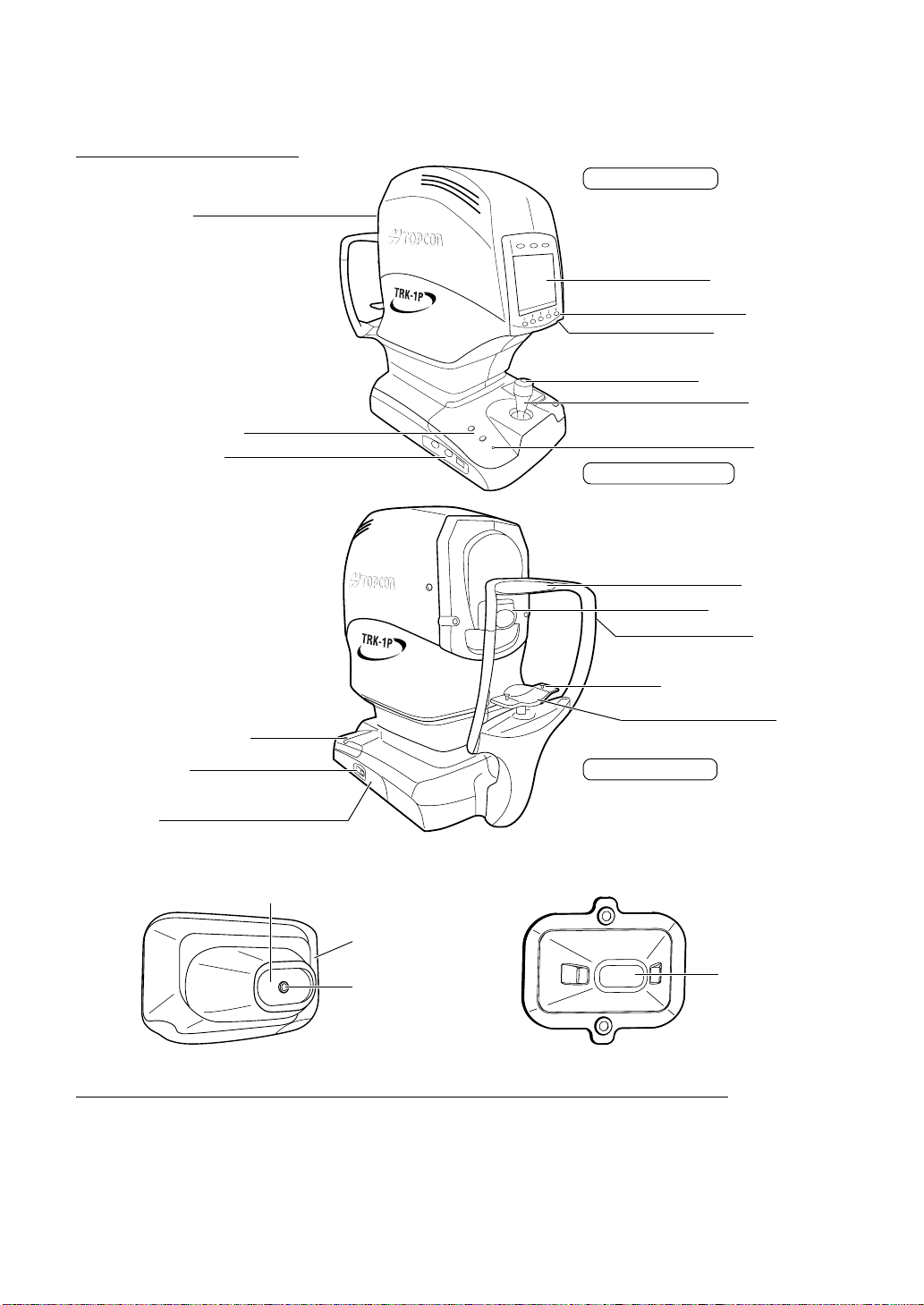
COMPONENT NAMES
Measuring head
Main body Section
Color LCD monitor
Control panel
Brightness control
Measurement switch
Control lever
Chinrest up/down button
External I/O terminal
Printer cover open button
POWER switch
Inlet cover
Measuring window at TONO/PACHO mode
Measuring window
Measuring opening
Power lamp
Power supply Section
Forehead rest
Measuring opening
Height mark
Chinrest tissue stopper pin
Chinrest
Chinrest Section
Measuring nozzle
COMPOSITION OF PARTS WHICH CONTACT THE HUMAN BODY
Forehead rest : Silicone rubber
Chinrest : Acrylonitrile butadiene styrene resin
12
COMPONENTS
Measuring window
lens cap
Page 14
CONTROL PANEL COMPONENTS (REF/KRT MODE)
(1) R/L (2) Mode (3) Print
R/K
(4) Function button
(1) R/L button: Switches between right and left eyes. Sets continuous measurement
of both eyes, measurement of the right eye only and measurement of
the left eye only.
(2) Mode button: Switches between REF/KRT mode and TONO/PACHO mode.
The Mode is selected:
Fully automatic measurement mode (REF/KRT mode changes to
TONO/PACHO mode continuously), REF/KRT mode and TONO/
PACHO mode.
Turns on in orange under REF/KRT mode and in greenish-blue
under TONO/PACHO mode.
(3) Print button: Prints out measurement results. When there is no measurement
value, this feeds printer paper by continuous pressing.
When the result is stored, the switch green.
(4) Function button: Sets functions under REF/KRT mode.
Functions are displayed as PAGES (PAGE 1, PAGE 2, PAGE 3) on
the screen.
13
COMPONENTS
Page 15
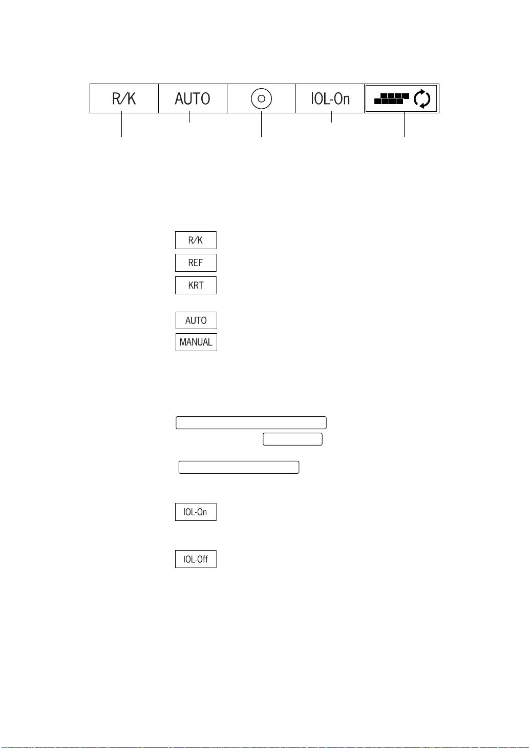
PAGE 1
After turning power on, the initial status of PAGE is as follows.
(6) Alignment button (8) IOL button
(5) Measurement mode button (7) Target image button (9) PAGE selecting button
(5) Measurement mode button:
Switches between measurement modes of REF/KRT mode. Pressing the Function button enables you to select R/K (REF/KRT continu ous measurement), REF (REF measurement) or KRT (KRT
measurement).
: REF/KRT continuous measurement
: REF measurement
: KRT measurement
(6) Alignment button: Switches between auto measurement and manual measurement.
: Auto measurement
: Manual measurement
(7) Target image button: Allows observation of the saved image on the monitor screen.
During the REF/KRT continuous measurement (R/K mode), you can
observe the target image by switching between REF and KRT
modes.
On the TARGET IMAGE DISPLAY screen, press th e
MEASUREMENT MODE button
ment, pressing the will change the right/left data.
To return to the MEASUREMENT screen, press the
MEASUREMENT switch
.
(8) IOL button: When errors are frequent in measuring an IOL-inser ted eye, pressing
the button may allow the measurement.
R/L button
. During the right/left measure-
(9) PAGE selecting button:
14
COMPONENTS
: Turned ON when errors are frequent.
IOL mark is displayed on the measuring screen if "ON" is
selected. (See page 19)
: Turned OFF during a normal measurement.
Changes the PAGE screen to another.
Page 16
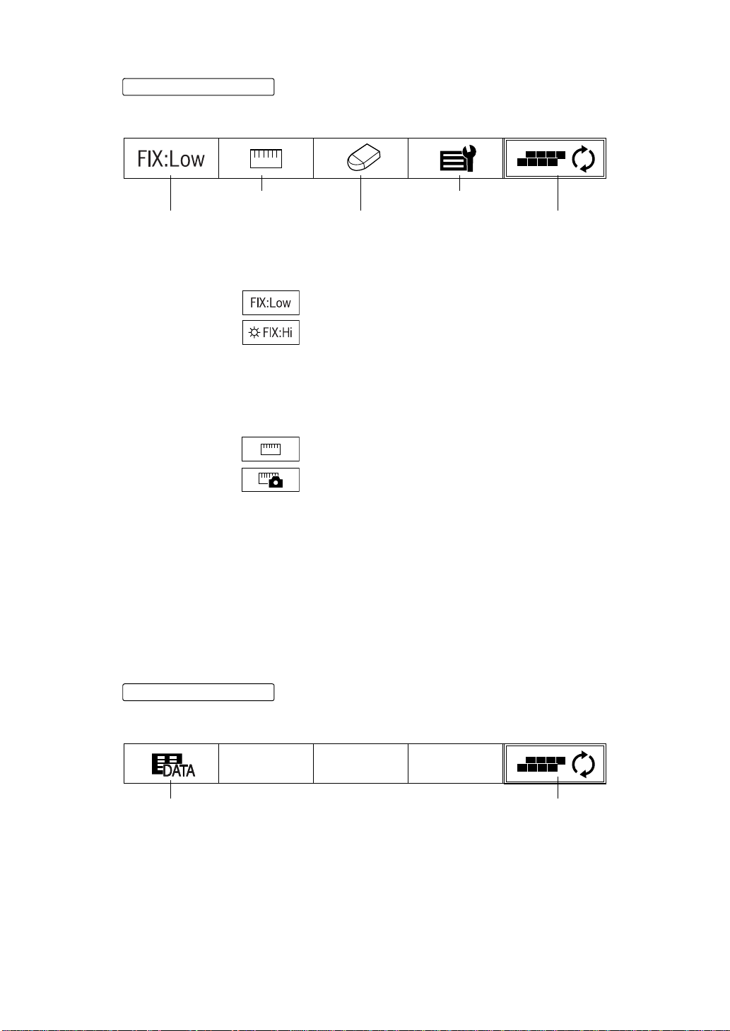
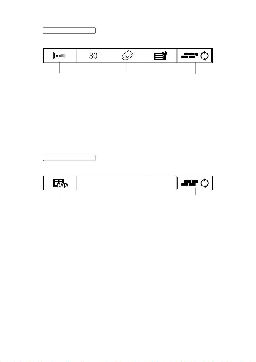
PAGE 2
PAGE selecting button
If the is pressed on PAGE 1, the status of PAGE changes as follows.
If the button is pressed again, PAGE 3 is changed.
(11) Cornea diameter button (13) R/K menu button
(10) Fixation target button (12) Clear button (14) PAGE selecting button
(10) Fixation target button:
Varies the brightness of fixation target.
: Darkens the fixation target.
: The brightness of fixation target to normal.
When Hi is selected, the fixation lamp mark appears on
the MEASUREMENT screen. (See page 19)
(1 1) Cornea diameter button:Used to measure the cornea diameter.
The measurement can be made by using actual image or static
image, and the status of button icon changes accordingly.
: Measuring actual image
: Measuring static image
For setting of the actual and static image, refer to "CHANGING THE
METHOD OF CORNEA DIAMETER MEASUREMENT" on page 44.
For measuring details, refer to "MEASURING THE CORNEA DIAMETER" on page 148.
This icon is not displayed in REF (REF single measurement).
(12) Clear button: Deletes measurement data.
(13) R/K menu button: Displays the MENU screen of REF/KRT mode.
(See "SETTING MENU (R/K)" on page 69)
(14) PAGE selecting button:Changes the PAGE screen to another.
PAGE 3
PAGE selecting button
If the is pressed on PAGE 2, the status of PAGE changes as follows.
If the button is pressed again, PAGE 1 is returned.
(15) All data button (16) Page selecting button
(15) All data button: Displays all measurement data on the screen. (See page 142)
(16) PAGE selecting button:
Changes the PAGE screen to another.
15
COMPONENTS
Page 17
CONTROL PANEL COMPONENTS (TONO/PACHO MODE)
(1) R/L (2) Mode (3) Print
(4) Function button
(1) R/L button: Switches between the righ t and left eyes. Sets continuou s measure-
ment of both eyes, measurement of the right eye only and measure-
ment of the left eye only.
(2) Mode button: Switches between REF/KRT mode and TONO/PACHO mode.
The Mode is selected:
Fully automatic measurement mode (REF/KRT mode changes to
TONO/PACHO mode continuously), REF/KRT mode and TONO/
PACHO mode.
Turns on in orange under REF/KRT mode and in greenish-blue
under TONO/PACHO mode.
(3) Print button: Prints out measurement results. When there is no measurement
value, this feeds printer paper by continuous pressing.
When the result is stored, the switch green.
(4) Function button: Sets functions under TONO/PACHO mode.
Functions are displayed as PAGES (PAGE 1, PAGE 2, PAGE 3) on
the screen.
16
COMPONENTS
Page 18
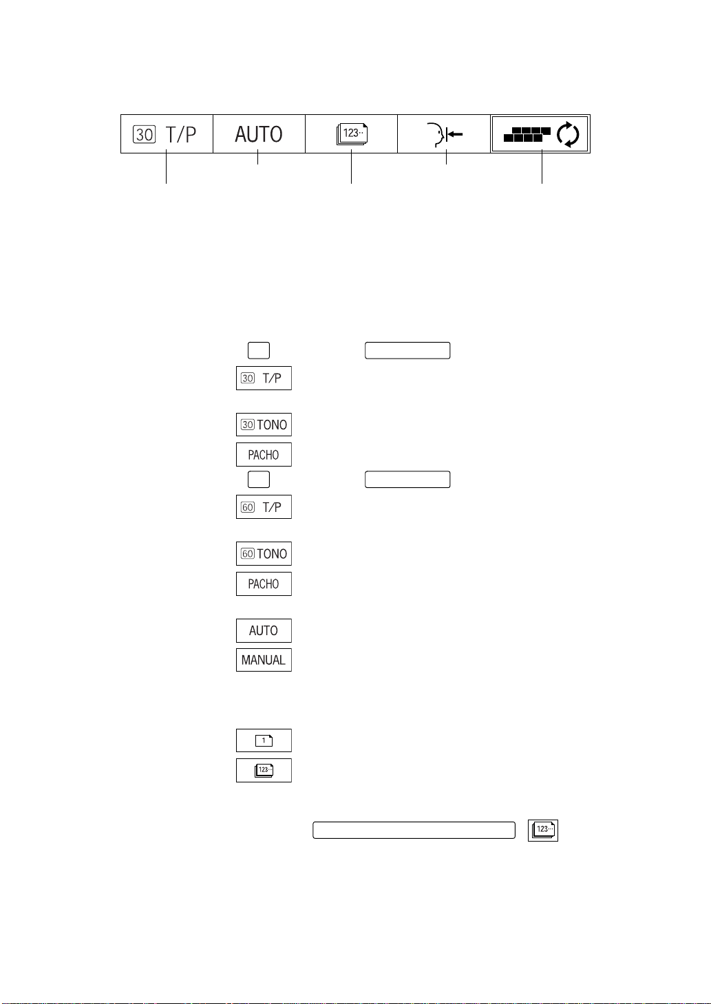
PAGE 1
After turning power on, the initial status of PAGE is as follows.
(6) Alignment button (8) Safety stop button
(5) Measurement mode button (7) Count change button (9) PAGE selecting button
(5) Measurement mode button:
Switches the measurement mod es of the ocular pressure measur e-
ment and the cornea thickness measurement.
Pressing the Function button enables you to select T/P (ocular pres-
sure measurement/cornea thickness continuous measurement),
TONO (ocular pressure measurement) or PACHO (cornea thickness
measurement).
30
If is selected by in Page 2:
: Ocular pressure measurement/cornea thickness
continuous measurement
: Ocular pressure measurement
: Cornea thickness measurement
30/60 button
60
If is selected by in PAGE 2:
: Ocular pressure measurement/cornea thickness
continuous measurement
: Ocular pressure measurement
: Cornea thickness measurement
(6) Alignment button: Switches between auto measurement and manual measurement.
: Auto measurement
: Manual measurement
(7) Count change button:In the AUTO measurement, the number of measurements can be
selected between "single measurement" and "the previously set
number of measurements".
: Single measurement
: Previously set number of measurements
This is not displayed under MANUAL mode.
When the measurement mode is changed by the
, is returned.
(8) Safety stop button: Used for position setting to keep the measuring window glass from
the patient's eye during the measurement. For details, see page 113.
(9) PAGE selecting button:Changes the PAGE screen to another.
MEASUREMENT MODE button
30/60 button
17
COMPONENTS
Page 19
PAGE 2
PAGE selecting button
If the is pressed on PAGE 1, the status of PAGE changes as follows.
If the button is pressed again, PAGE 3 is returned.
(11) 30/60 button (13) T/P menu button
(12) Clear button(10) Air check button
(14) PAGE selecting button
(10) Air check button: Checks correct operations of the measurement system inside the
instrument. For detail, see page 111.
(11) 30/60 button: Switches between 0-30 range and 0-60 range. This is not displayed
under PACHO mode.
(12) Clear button: Deletes measurement data.
(13) T/P menu button: Displays the MENU screen of TONO/PACHO mode.
(See "SEETING MENU (T/P)" on page 81)
(14) PAGE selecting button:
Changes the PAGE screen to another.
PAGE 3
PAGE selecting button
If the is pressed on PAGE 2, the status of PAGE changes as follows.
If the button is pressed again, PAGE 1 is returned.
(15) All data button (16) PAGE selecting button
(15) All data button: Displays all measurement data on the screen. (See page 142)
(16) PAGE selecting button:
Changes the PAGE screen to another.
18
COMPONENTS
Page 20
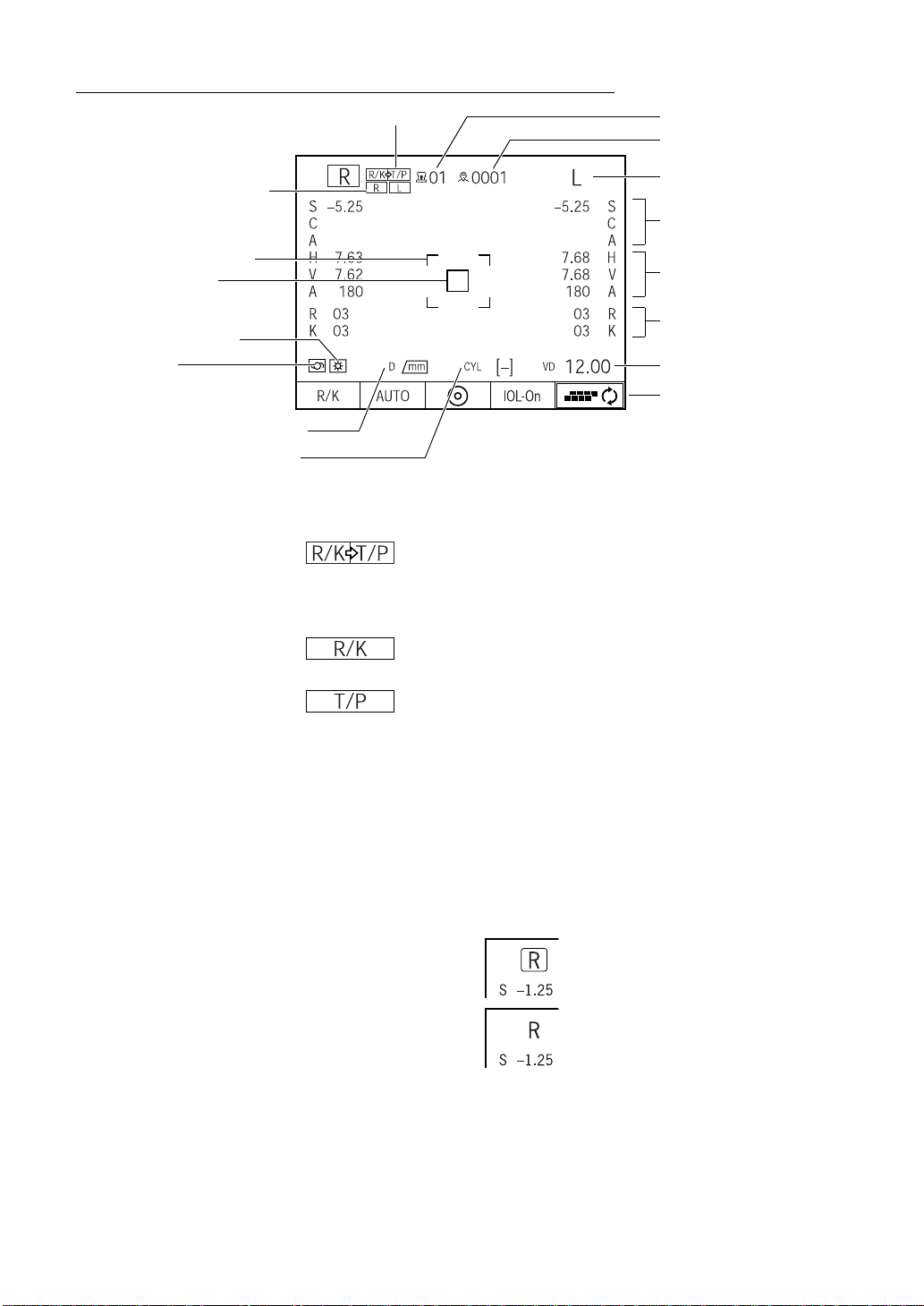
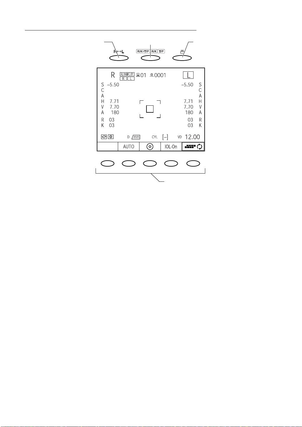
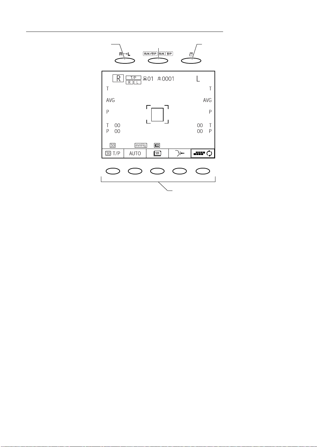
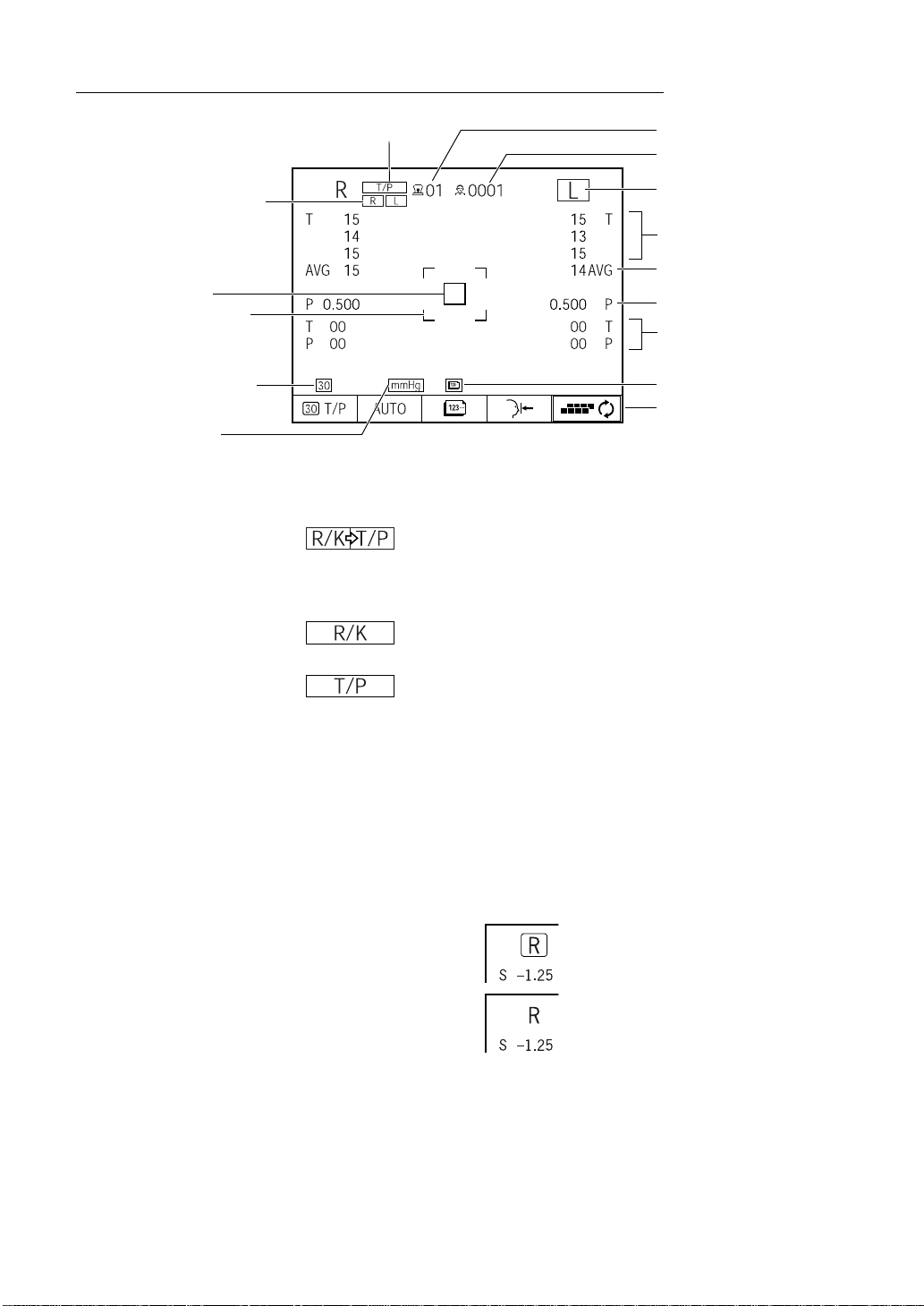
MONITOR SCREEN COMPONENTS (REF/KRT MODE)
(2) Instrument No.(1) Mode display
(3) Patient No.
(16) Selected measuring eye
mark
(12) Outer alignment mark
(13) Alignment mark
(15) Fixation lamp mark
(14) IOL mark
(9) Measurement result unit setting
(10) Set value of CYLINDER sign
(4) Right/left eye
(5) REF measurement value
(6) KRT measurement value
(7) Number of REF/KRT
measurements
(11) VD setting
(8) Function menu
(1) Mode display: Displays measurement mode of REF/KRT and TONO/PACHO.
: Fully automatic measurement mode.
Measurements in REF/KRT and TONO/PACHO are
continuously carried out.
Measuring begins in REF/KRT mode.
: REF/KRT mode. REF and KRT measurements are
available.
: TONO/PACHO mode. Ocular pressure and cornea
thickness measurements are available.
(2) Instrument No.: Displays the instrument No.
In the INITIAL MENU screen, setting and display/nondisplay can be
switched. (See page 43)
(3) Patient No.: Displays the patient No.
In the INITIAL MENU screen, setting and display/nondisplay can be
switched. Also, the patient No. received from an external device (bar-
code reader and the like) is displayed. (See page 42)
(4) Right/left eye: Displays the right/left eye of the patient.
The display in measurement is framed.
Measured :
The other measured :
19
COMPONENTS
Page 21
(5) REF measurement value:
Displays the REF measurement value.
Of measurement values, the latest data is displayed on the screen.
Figures only: When the measurement was done correct.
Figures with *: When the reliability of measurement is low.
ERROR: When the measurement was not done correctly.
(6) KRT measurement value:
Displays the KRT measurement value.
The latest measurement data is displayed on the screen.
In the INITIAL MENU screen, the display of HV (horizontal/vertical
direction) and R1R2 (major meridian direction) can be switched.
(See page 76)
(7) Number of REF/KRT measurements:
Displays the number of REF and KRT measurements.
(8) Function menu: Display the function button under REF/KRT mode.
For details, see "CONTROL PANEL COMPONENTS (REF/KRT
MODE)" on page 13.
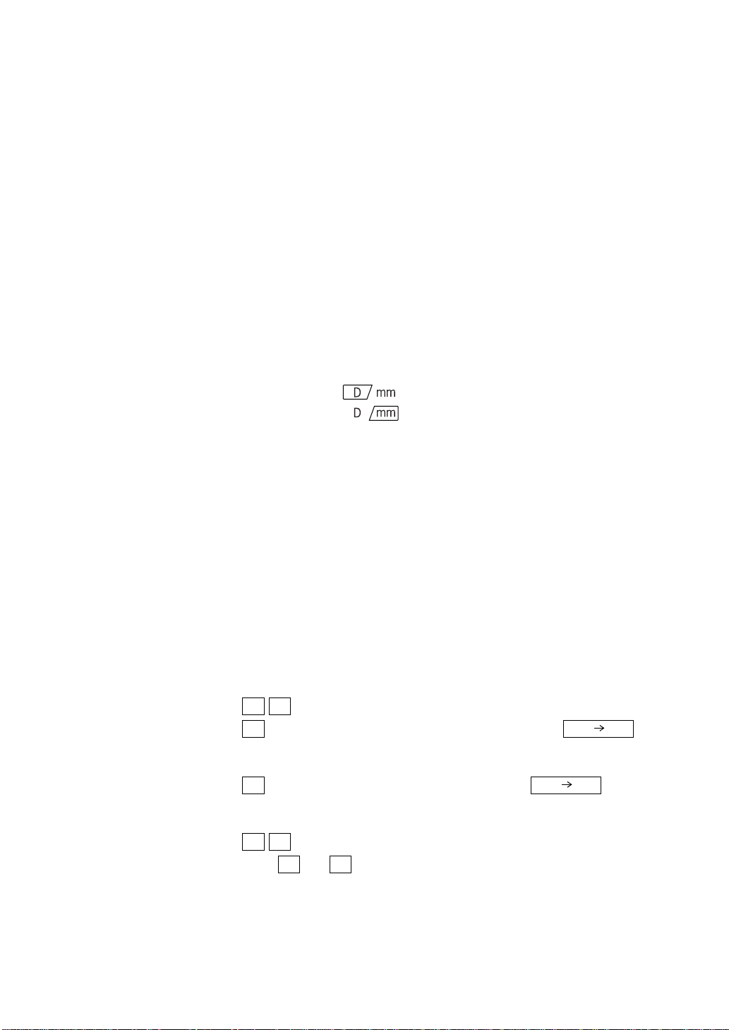
(9) Measurement result unit setting:
Displays the unit of the result of KRT measurement (diopter or mm).
Diopter setting :
mm setting :
The setting can be changed in the INITIAL MENU screen. (See page
75)
(10) Set value of CYLINDER sign:
Displays the CYL set value.
The setting can be changed in the INITIAL MENU screen. (See page
77)
(11) VD setting: Displays the set value of vertex distance.
The setting can be changed in the INITIAL MENU screen. (See page
73)
(12) Outer alignment mark:
Used to get coarse alignment in aiming at the patient's eye.
(13) Alignment mark: Indicates the starting area of auto alignment.
(14) IOL mark: Displayed when the IOL button is ON.
(15) Fixation lamp mark:Displayed when the Fixation button is Hi.
(16) Selected measuring eye mark:
Selected patient's eye is shown.
R L
R R/K T/P
L R/K T/P
R L
After or is selected, automatically return to initial setting
(continuous measurement), if printing is carried out.
:Both eyes are measured continuously.
:Only the right eye is measured. When fully
automatic measurement mode is selected, only the right
eye is measured repeatedly.
:Only the left eye is measured. When fully auto-
matic measurement mode is selected, only the left eye is
measured repeatedly.
continuous measurement is set in initial settings.
R L
20
COMPONENTS
Page 22
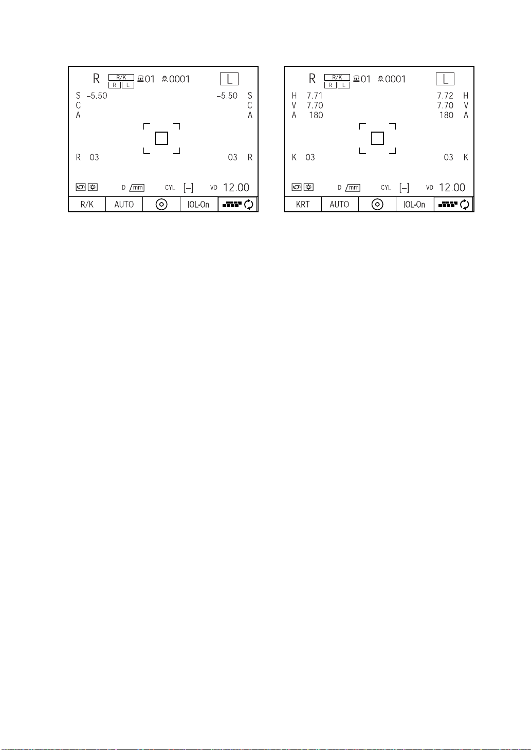
REF mode KRT mode
21
COMPONENTS
Page 23
MONITOR SCREEN COMPONENTS (TONO/PACHO MODE)
(2) Instrument No.(1) Mode display
(3) Patient No.
(15) Selected measuring eye
mark
(11) Alignment mark
(12) Outer alignment mark
(13) Measuring range mark
(14) Ocular Pressure
(Value unit) mark
(4) Right/left eye
(5)
TONO measurement value
(6) TONO average value
PACHO measurement value
(7)
(8)
Number of TONO/PACHO
measurements
(10) Number of
measurements mark
(9) Function menu
(1) Mode display: Displays measurement mode of REF/KRT and TONO/PACHO.
: Fully automatic measurement mode.
Measurements in REF/KRT and TONO/PACHO are
continuously carried out.
Measuring begins in REF/KRT mode.
: REF/KRT mode. REF and KRT measurements are
available.
: TONO/PACHO mode. Ocular pressure and cornea
thickness measurements are available.
(2) Instrument No.: Displays the instrument No.
In the INITIAL MENU screen, setting and display/nondisplay can be
switched. (See page 43)
(3) Patient No.: Displays the patient No.
In the INITIAL MENU screen, setting and display/nondisplay can be
switched. Also, the patient No. received from an external device (bar-
code reader and the like) is displayed. (See page 42)
(4) Right/left eye: Displays the right/left eye of the patient.
The display in measurement is framed.
22
COMPONENTS
Measured :
The other measured :
Page 24
(5) TONO measurement value:
Displays ocular pressure measurement values.
For one eye, three measurement values are displayed on the screen,
and thereafter the oldest measurement value is deleted.
White figures: When the measurement was done correct.
[ ]Yellow figures: When the reliability of measurement is low.
ERROR: When the measurement was not done correctly.
OVER: When the measurement range is exceeded.
(6) TONO average value:Displays the average value of ocular pressur e measurements. Inte-
ger/decimal representation of the average value can be selected on
the setting menu (see page 82).
(7) PACHO measurement value:
Displays the cornea thickness measurement value.
Only the latest measurement data is displayed in the screen.
(8) Number of TONO/PACHO measurements:
Displays the number of ocular pressure and cornea thickness mea-
surements.
(9) Function menu: Displays the function button under TONO/PACHO mode.
For details, see "CONTROL P ANEL COMPONENTS (TONO/PACHO
MODE)" on page 16.
(10) Count change mark:In the AUTO measurement, the number of measurements can be
selected between "single measurement" and "the previously set
number of measurements". For details, see "CHANGING THE NUM-
BER OF MEASUREMENTS" on page 141. This is not displayed
under MANUAL mode.
: Single measurement
: Previously set number of measurements
(11) Alignment mark: Indicates the starting area of auto alignment.
(12) Outer alignment mark: Used to get coarse alignment in aiming at the patient's eye.
(13) Measuring range mark:
The measuring range set by the 30/60 button is displayed. Th is is not
displayed under PACHO mode.
(14) Ocular Pressure (Value unit) Mark:
Indicates the unit of the measured ocular pressure value.
In the INITIAL MENU screen, the unit can be selected. (see p.48)
This is not displayed under PACHO mode.
(15) Selected measuring eye mark:
Selected patient's eye is shown.
R L
R R/K T/P
L R/K T/P
R L
After or is selected, automatically return to initial setting
(continuous measurement), if printing is carried out.
:Both eyes are measured continuously.
:Only the right eye is measured. When fully
automatic measurement mode is selected, only the right
eye is measured repeatedly.
:Only the left eye is measured. When fully auto-
matic measurement mode is selected, only the left eye is
measured repeatedly.
continuous measurement is set in initial settings.
R L
23
COMPONENTS
Page 25
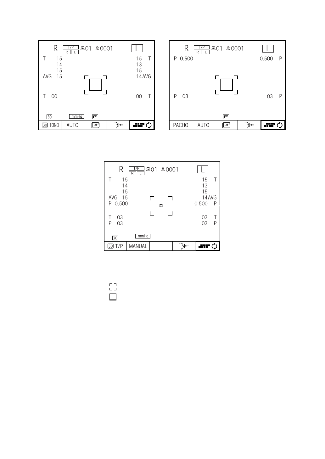
TONO mode PACHO mode
MEASUREMENT SCREEN UNDER MANUAL MODE
(16) Inner alignment mark:
Used to get alignment in aiming at the patient's eye in manual mode.
Change the mark according to the status of alignment.
: Alignment is insufficient.
: Alignment is sufficient in back/forth, left/right and up/down
directions (in the range where measuring is possible).
For details, see MEASUREMENT UNDER MANUAL MODE (TONO/
PACHO mode) on page 124.
(16) Inner alignment mark
24
COMPONENTS
Page 26
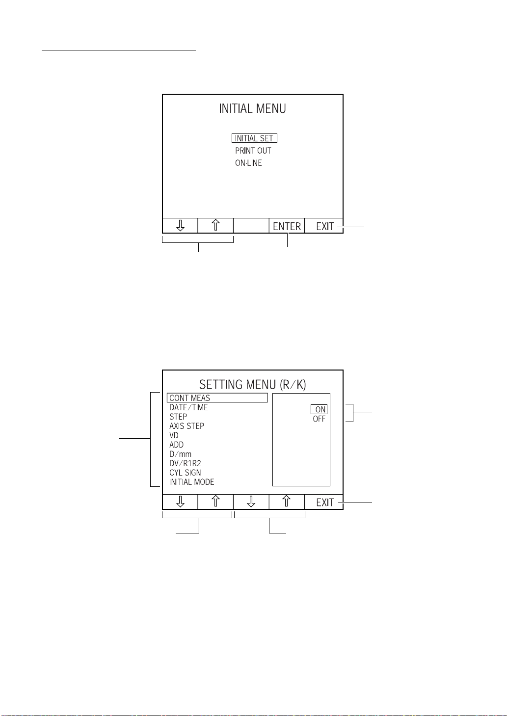
OTHER SCREEN DISPLAYS
INITIAL SETTING SCREEN
(1) Set item change button (2) Execution button
(1) Set item change button: Move the cursor up/down and select the set item.
(2) Execution button: Execute the menu selected by the cursor.
(3) Menu end button: Quit the MENU screen and save the set content.
(3) Menu end button
MENU SETTING SCREEN (REF/KRT MODE)
(2) Set value
(1) Set item
(5) Menu end button
(4) Set value change button(3) Set item change button
(1) Set item: Displays settable menu items. (The cursor is yellow.)
(2) Set value: Displays the set content of set items and the cur rent settings.
The cursor is displayed on the content being set. (The cursor
is blue.)
(3) Set item change button: Move the yellow cursor up/down and select the set item.
(4) Set value change button: Move the blue cursor up/down and select the set value.
(5) Menu end button: Quit the MENU screen and save the set content.
25
COMPONENTS
Page 27
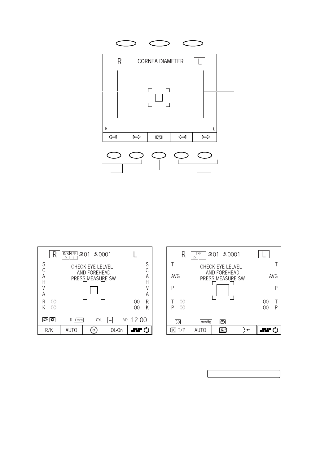
CORNEA DIAMETER MEASUREMENT SCREEN
(1) Left positioning bar
(3) Move left positioning bar button (4) Move right positioning bar button(5) Initial position button
(1) Left positioning bar: Set the left position of cornea diameter measurement.
(2) Right positioning bar: Set the right position of cornea diameter measurement.
(3) Move left positioning bar button: Move the left positioning bar right/left.
(4) Move right positioning bar button:Move the right positioning bar right/left.
(5) Initial position button: The bar returns to the initial position.
WAITING SCREEN
(2) Right positioning bar
REF/KRT mode TONO/PACHO mode
This screen appears after powering on, after printing out and after clearing data.
If the screen is displayed, no measurement is done.
In this case, following the screen message, pressing the will
enable measurement.
MEASUREMENT switch
26
COMPONENTS
Page 28
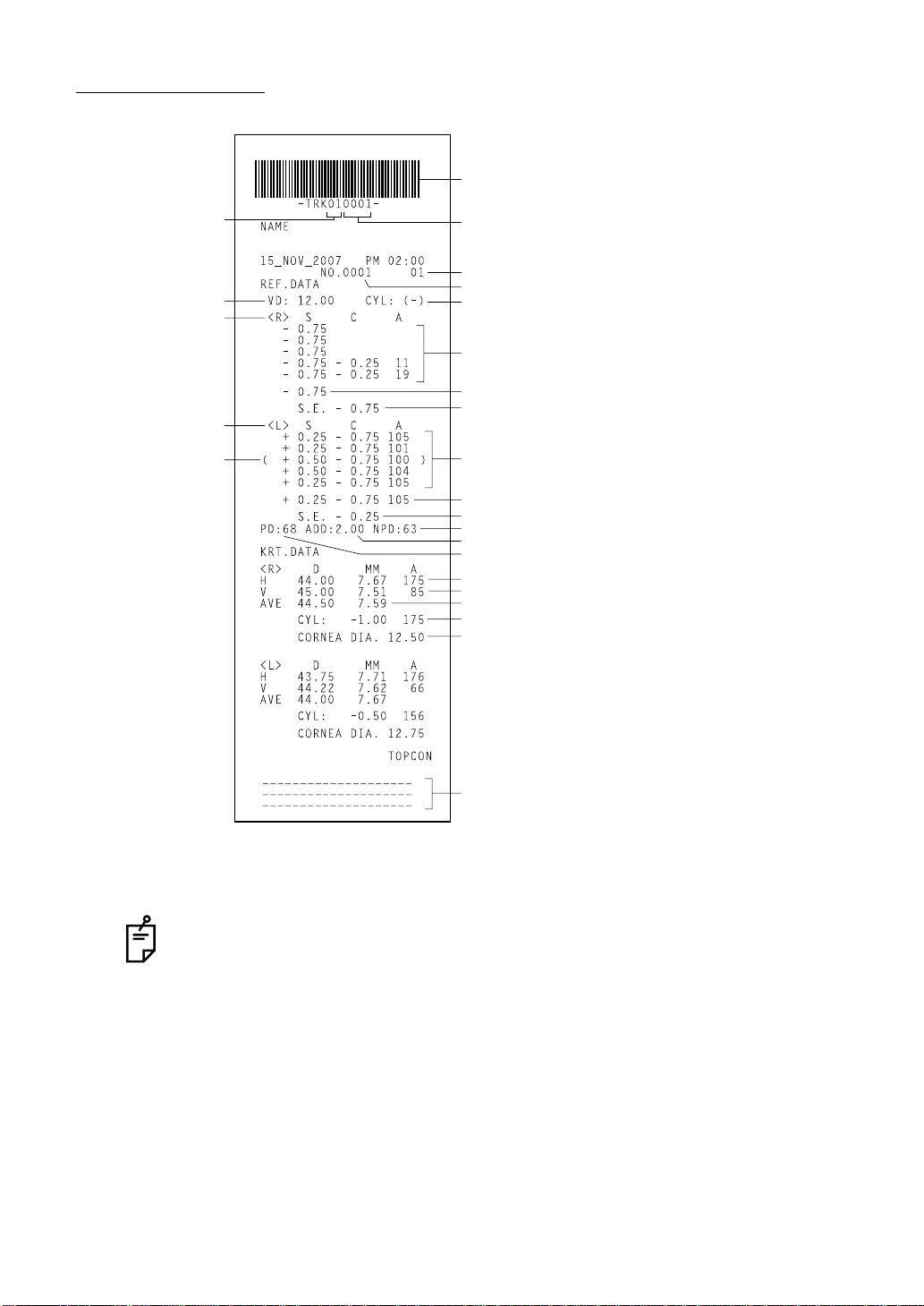
PRINTER OUTPUT
<R/K> MODE
Bar code
Instrument No.
VD (vertex distance)
Right eye measurements
Left eye measurements
The ( ) mark is added
when measurement
values are not fully
reliable.
Work ID No.
Instrument No.
Patient No.
Cylindrical power mark
Measurement Results of 5 right eye measurements
(recordable up to 10 measurements)
Typical value of right eye (The * mark is displayed when
3 or more measurements are done.)
SPHERICAL EQUIVALENT of right eye
Measurement Results of 5 left eye measurements
(recordable up to 10 measurements)
Typical value of left eye
SPHERICAL EQUIVALENT of left eye
Near vision PD value
ADD (ordinary additional power)
Pupil distance (PD value)
Measured value of horizontal corneal curvature
Measured value of vertical corneal curvature
Average value
Corneal astigmatic power
Cornea diameter
Message column
(If the message is entered, it will be displayed in any mode.)
(Example) REF data “ALL”, KRT data “AVE”
The near-vision PD value is calculated based on the general addition number.
COMPONENTS
27
Page 29
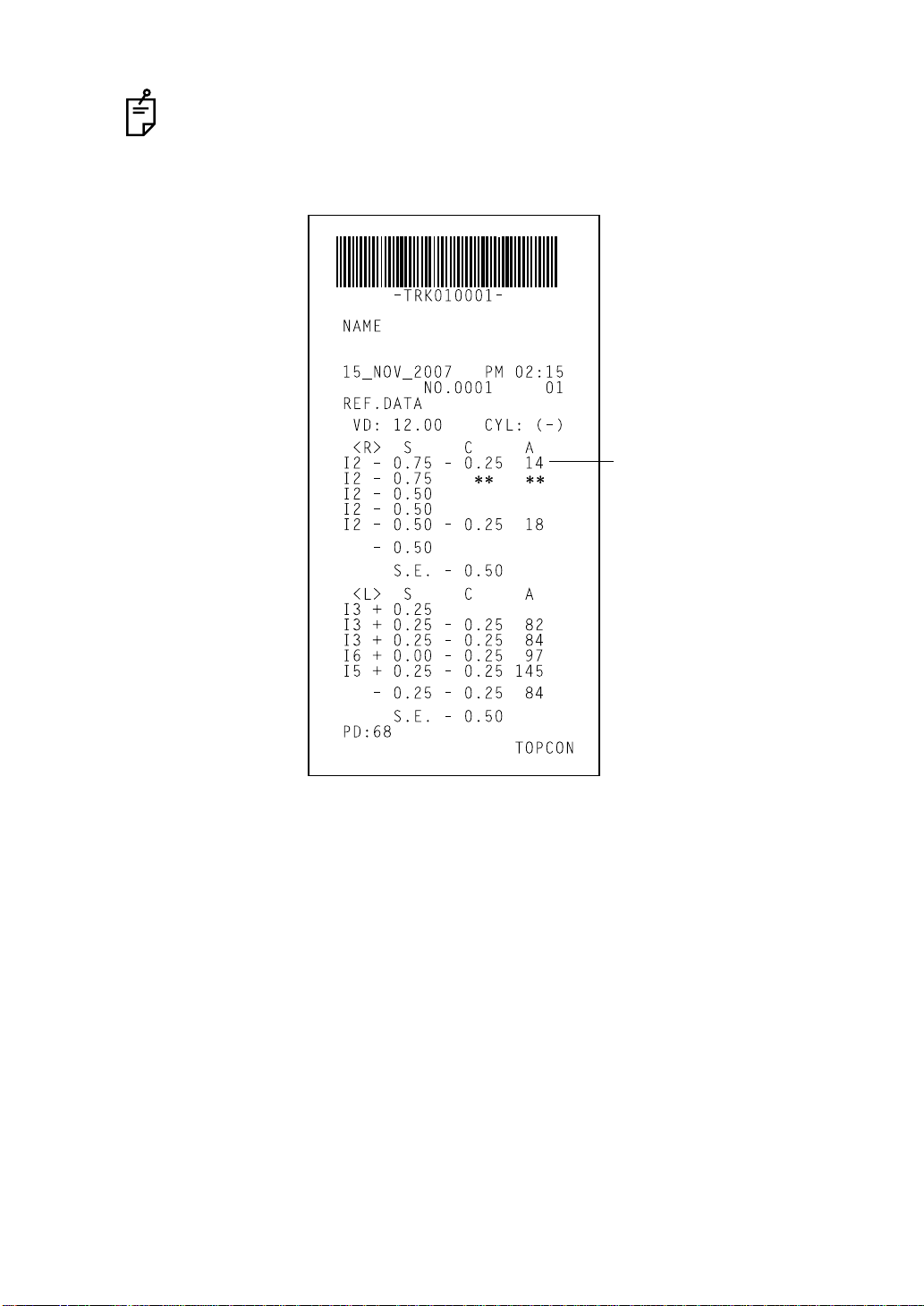
When measurement is done under the IOL mode, a reliability factor is printed out
following the I mark.
The reliability factor is formed with integers 1 to 9 in increasing order of reliability.
Additionally, if the reliability is high enough, the reliability factor is not shown in the
printout.
The I mark is displayed at IOL
mode.
If the reliability is low and values
of C and A cannot be determined,
** marks are given to pertaining
columns.
28
COMPONENTS
Page 30
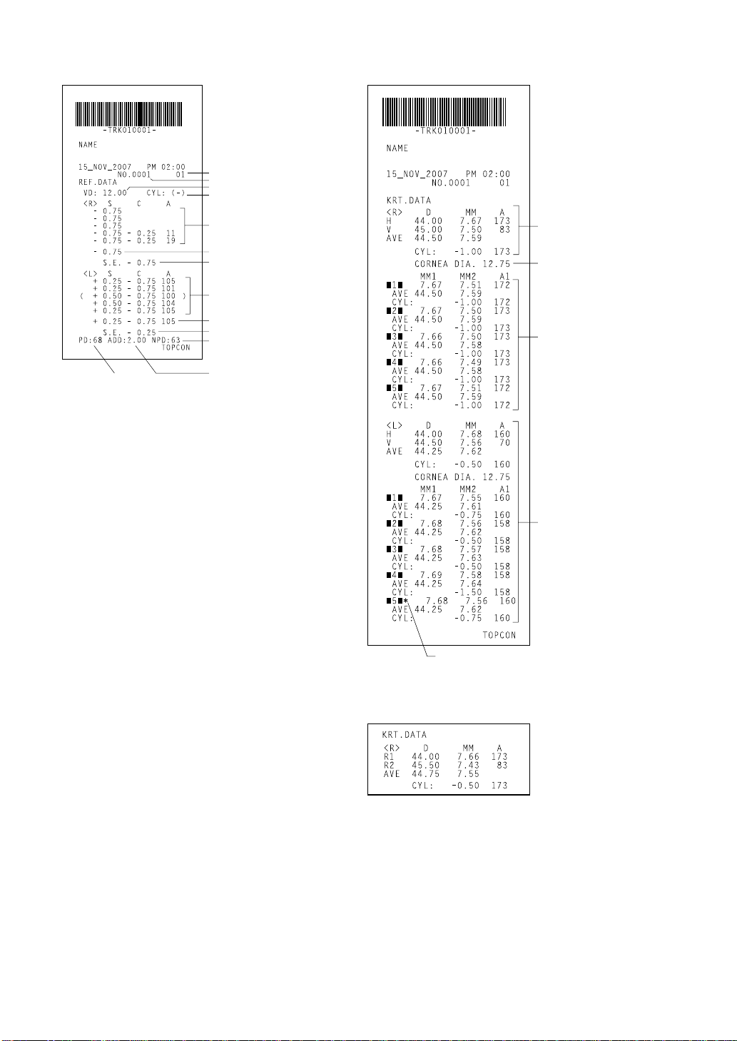
<REF> MODE <KRT> MODE
Instrument No.
Patient No.
VD (vertex distance)
Cylindrical power mark
Results of 5 refractory power measurements of right eye (recordable
up to 10 measurements)
Typical value of right eye
Typical value of right eye
SPHERICAL EQUIVAL ENT
of right eye
Results of 5 refractory power mea-
surements of left eye (recordable
up to 10 measurements)
Typical value of left eye
SPHERICAL EQUIVALENT of left eye
Near vision PD value
Pupil distance
(PD value)
ADD(ordinary additional power)
Typical measured value
of right eye corneal
curvature
Measured value of right
eye cornea (mm)
Results of 5 right eye corneal curvature measurements of right eye,
average value and astigmatic power of cornea
(recordable up to 10 measurements each for right /
left eye)
Reliability mark
(displayed only when reliability is low)
<R/K> <KRT> MODE
(Kerato data is printed as below
when H/V is set to R1/R2.)
Measured value of left eye
29
COMPONENTS
Page 31

<T/P> MODE
Bar code
Instrument No.
Measured of intraocular
pressure values
Measured value of central
corneal thickness
Work ID No.
Instrument No.
Patient No.
Measured intraocular pressure values
Average intraocular pressure values
Measured value of central corneal
thickness
Average value of central corneal
thickness
Printed example on setting the display unit of intraocular pressure measurement
values at hPa.
30
COMPONENTS
Measurement value at the unit of mmHg
Measurement value at the unit of hPa
Page 32

<TONO> MODE <PACHO> MODE
Measured intraocular
pressure values
Average intraocular
pressure values
Measured value of
central corneal
thickness
Average value of
central corneal
thickness
Printed example on setting the display unit of intraocular pressure measurement
values at hPA on TONO mode.
31
COMPONENTS
Page 33

STANDARD ACCESSORIES
The following are standard accessories. Make sure that all these items are included (quantity).
Power cable (1) Chinrest tissue pin (2)
Printer paper (2) Silicon cloth (1)
Chinrest tissue (1) Dust cover (1)
Fuse (2) Instruction manual, unpacking and assembling
(1 each)
Accessory case (1) Model eye (1)
Hexagon wrench (1) Window glass cleaning procedure (1)
Blower (1) Cotton applicator for nozzle cleaning (1)
Measuring window lens cap (1)
32
COMPONENTS
Page 34

PREPARATIONS
INSTALLING THE INSTRUMENT
When moving the instrument, be sure to hold it at the base with
two persons. Carrying by one person may cause harm to his
CAUTION
CAUTION
back or injury by falling parts. Also, holding areas other than
the base may cause injury, as well as damage to the instrument.
When setting an instrument on an instrument table, pay attention not to injure the patient's fingers between the instrument
and the table.
CAUTION
To avoid injury, do not install the instrument on a slope or on an
unstable place.
1 Hold the instrument body firmly at the specified positions and place it on the automatic
instrument table.
For the automatic instrument table, see "OPTIONAL ACCESSORIES" on page 164.
Holding positions Holding the instrument
2 Place the instrument horizontally, with care not to trample cables.
33
PREPARATIONS
Page 35

CONNECTING THE POWER CABLE
WARNING
CAUTION
To avoid fire and electric shocks by short circuiting, be sure to
connect the instrument into a grounded outlet.
To avoid electrical shock, do not handle the power plug with
wet fingers.
1 Make sure the instrument is OFF.
2 Remove the inlet cover.
Make sure you can see the mark "O"
(it shows power is OFF).
3 Connect the power cable to the instrument body.
34
PREPARATIONS
Page 36

4 Then put the inlet cover.
5 Plug the power cable into the 3-pin AC outlet with grounding.
CONNECTING EXTERNAL I/O TERMINALS
Use the external device complying with IEC60950/IEC60950-1 or UL60950/
UL60950-1.
DATA OUTPUT
This instrument can be connected to another device, including a personal computer via the
RS232C or USB terminal.
1 Connect the cable to the RS232C OUT terminal of the instrument.
2 Connect the other cable end to the PC and other extern al device.
RS232C IN terminal
RS232C OUT terminal
USB OUT terminal can be connected to Series B plug.
When connecting cable, be sure to use the cable with correct shape of plug.
DATA INPUT
This instrument can be connected to another device, including a barcode reader via the
RS232C terminal.
USB OUT terminal
1 Connect the cable to the RS232C IN terminal of the instrument.
2 Connect the other cable end to the external device.
For inquiries about the RS232C, call your dealer or TOPCON at the address
printed on the back cover of this manual.
35
PREPARATIONS
Page 37

FUNCTION SETTINGS BY MEANS OF MENU
LIST OF MENUS
MAIN MENU SUB MENU MENU ITEMS SETTING ITEMS Page
INITIAL
SETTING
INITIAL
SETTING
SETTING
PRINTOUT
BUZZER Setting the buzzer sound 39
INIT AUTO Setting the start mode after turning the
power on
AUTO PRINT Auto print after finishing auto measure-
ment
PRINT SWITCH Selecting print button functions 41
SERIAL No. RESET Setting the power resetting the patient
No.
SERIAL No. INPUT Setting the patient No. 42
SERIAL No. DISPLAY Displaying the patient No. 42
INSTRUMENT No. INPUT Setting the instrument No. 43
INSTRUMENT No. DISPLAY Displaying the instrument No. 43
DIOPTER SHIFT Shifting the refractory power 44
C.D MEMORY Changing the method of cornea diameter
measurement
MEASURING MODE Setting the measurement mode after
powering on
POWER ON MODE Setting the measurement mode under R/
K and T/P mode after power-on
POSITION SET Setting the waiting position after mea-
surement
POWER SAVE TIME Setting the power save time 47
AUTO MEASURE COUNT Setting the number of continuous mea-
surements
UNIT SELECT Setting the display unit of ocular pressure
measurement values
VD PRINT Printing VD values 49
CYL PRINT Printing the CYLINDER sign 50
REF PRINT FORM Changing the printout format of refraction
measurement values
S.E DATA Printing the SPHERICAL EQUIVALENT
(s.e. data)
GRAPHIC PRINT Printing the REFRACTION 51
PD PRINT Printing PD values 52
CL PRINT Printing COMPUTERIZED LENSME-
TER data
CREDIBILITY NUM Printing the credibility number 53
ADD PRINT Printing the addition number 53
KRT PRINT FORM Changing the printout format of cornea
measurement values
40
40
41
44
45
46
46
47
48
50
51
52
54
36
PREPARATIONS
Page 38

MAIN MENU SUB MENU MENU ITEMS SETTING ITEMS Page
(INITIAL
SETTING)
MENU
SETTING
(SETTING
PRINTOUT)
ON-LINE
SETTING
R/K CONT.MEAS. Setting cont. Meas. (continuous mea-
T/P DATE/TIME Setting the date and time 81
KRT AVE PRINT Printing th e average value of cornea
shape measurements
KRT DATA ORDER Changing the PRINTING SEQUENCE
cornea shape measurement values
KRT CYL PRINT Printing corneal astigmatism and AXIS 55
PRINT R/L Changing the PRINTING SEQUENCE 56
BAR CODE PRINT Printing the barcode 56
NAME PRINT Printing names 57
DATE PRINT Printing the date 57
DATE PRINT FORM Changing the printout format of date dis-
play
SERIAL No. PRINT Printing the patient No. 58
INSTRUMENT No. PRINT Printing the instrument No. 59
TOPCON PRINT Printing the TOPCON mark 59
PRINT DATA Setting for printing the measurement
result
OUTPUT DATA TYPE Selecting the output data format 62
DATA FORM Setting the communication format 63
DATA OUTPUT PORT Selecting the output port 65
BAUD-RATE Setting the speed of RS-232C communi-
cation
CL INPUT Computer the lensmeter data receiving
format
surement)
DATE/TIME Setting the date and time 70
STEP Setting step 71
AXIS STEP Setting axis step 72
VD Setting VD 73
ADD Setting the addition number 74
D/mm Setting D/mm 75
HV/R1R2 Setting HV/R1R2 76
CYL SIGN Setting CYLINDER sign 77
INITIAL MODE Setting the measurement mode under
REF/KRT mode
MESSAGE INPUT Setting message input 79
AVERAGE MODE Setting the average value of ocular pres-
sure measurements
INITIAL MODE Setting the measurement mode under
TONO/PACHO mode
MESSAGE INPUT Setting message input 84
54
55
58
60
65
66
69
78
82
83
37
PREPARATIONS
Page 39

INITIAL SETTING
In the initial setting, patient No., instrument No., refractory power shift, data input/output,
printer output, etc. can be set.
PREPARATION FOR INITIAL SETTING
1 Make sure the power cable is connected.
For connection, see "CONNECTING THE POWER CABLE" on page 34.
2 While pressing the of the control panel, press on the .
Continue to press the till the buzzer sounds. The POWER lamp lights
and the INITIAL MENU screen is displayed.
MENU button
MENU button
Menu button
POWER switch
RETURNING TO THE MEASUREMENT SCREEN
1 Press .
EXIT
2 Initialization starts, and the START UP screen is displayed.
38
PREPARATIONS
Page 40

INITIAL SETTING
In the INITIAL SET screen, buzzer sound, start mode, pa tient No., refracto ry power shif t, monitor display of typical value, method of corneal diameter measurement, etc. can be changed.
1 In the "INITIAL MENU screen," make sure that the cursor is on "INITIAL SET," and then
press . The monitor screen is changed to the "INITIAL SET screen."
ENTER
To exit from this screen
• Press .
• Close the "INITIAL SET screen" and return to the "INITIAL MENU screen".
To return to the previous item in the screen:
• Press the Set item change button .
EXIT
SETTING THE BUZZER SOUND
The buzzer sound can be turned ON/OFF. Before shipment, it is set to "ON" (buzzer sound).
1 In the "INITIAL MENU screen," select "INITIAL SET" and get the "INITIAL SET screen."
2 Press the Set value change button or and select "ON" (buzzer sound) or
"OFF" (no buzzer sound) of "BUZZER."
3 Setting is done by pressing the Set item change button , and the cursor goes to the
next item.
39
PREPARATIONS
Page 41

SETTING THE START MODE AFTER TURNING THE POWER ON
The start mode after powering on can be changed. Before shipment, it is set to "AUTO" (auto
measurement after powering on).
1 In the "INITIAL MENU screen," select "INITIAL SET" and get the "INITIAL SET screen."
2 Press the Set item change button and bring the cursor to "INIT AUTO."
3 Press the Set value change button or and select "AUTO" (auto measurement
after powering on) or "MANUAL"(manual measurement after powering on).
4 Press the Set item change button ; the setting is done and the cursor moves to the
next item.
AUTO PRINT AFTER FINISHING AUTO MEASUREMENT
After finishing the measurement of right and left eyes under auto measurement, the result can
automatically be printed. Before shipment, it is set to "ON" (auto print).
1 In the "INITIAL MENU screen," select "PRINT OUT" and get the "PRINT OUT screen."
2 Press the Set item change button and bring the cursor to "AUTO PRINT."
3 Press the Set value change button or and select "ON" (auto printout) or "OFF"
(no auto print).
4 Press the Set item change button ; the cursor moves to the next item.
40
PREPARATIONS
Page 42

SELECTING PRINT BUTTON FUNCTIONS
The Print button function can be changed. Before shipment, it is set to "ON" (print).
1 In the "INITIAL MENU screen," select "INITIAL SET" and get the "INITIAL SET screen."
2 Press the Set item change button and bring the cursor to "PRINT SWITCH."
3 Press the Set value change button or and select "ON" (print) or "OFF" (do not
print).
4 Press the Set item change button ; the cursor moves to the next item.
SETTING THE POWER RESETTING THE PATIENT No.
The patient No. can be reset by powering on. Before shipment, it is set to "OFF" (do not reset).
1 In the "INITIAL MENU screen," select "INITIAL SET" and get the "INITIAL SET screen."
2 Press the Set item change button and bring the cursor to "SERIAL No. RESET."
3 Press the Set value change button or and select "ON" (reset) or "OFF" (do not
reset).
4 Press the Set item change button ; the cursor moves to the next item.
41
PREPARATIONS
Page 43

SETTING THE PATIENT No.
The patient No. can be set between 0 and 9999. Before shipment, it is set to "0001."
1 In the "INITIAL MENU screen," select " INITIAL SET" and get the " INITIAL MENU
screen."
2 Press the Set item change button and bring the cursor to "SERIAL No. INPUT."
3 Press the Set value change button to decrease the value, or to increase.
4 Press the Set item change button ; the cursor moves to the next item.
Press the , and the cursor moves to the next
PATIANT No.'s digit to input.
DISPLAYING THE PATIENT No.
The patient No. can be displayed in the monitor screen. Before shipment, it is set to "ON."
MEASUREMENT switch
1 In the "INITIAL MENU screen," select "INITIAL SET" and get the "INITIAL MENU screen."
2 Press the Set item change button and bring the cursor to "SERIAL No. DISPLAY."
3 Press the Set value change button or and select "ON" (display) or "OF F" (do
not display).
4 Press the Set item change button ; the cursor moves to the next item.
42
PREPARATIONS
Page 44

SETTING THE INSTRUMENT No.
The instrument No. can be set between 0 and 99. Before shipment, it is set to "01."
1 In the "INITIAL MENU screen," select "INITIAL SET" and get the "INITIAL MENU screen."
2 Press the Set item change button and bring the cursor to "INSTRUMENT No.
INPUT."
3 Press the Set value change button to decrease the value, or to increase.
4 Press the Set item change button ; the cursor moves to the next item.
Press the , and the cursor moves to the next INSTRUMENT No.'s digit to input.
DISPLAYING THE INSTRUMENT No.
The instrument No. can be displayed on the monitor screen. Before shipment, it is set to
"OFF" (do not display).
MEASUREMENT switch
1 In the "INITIAL MENU screen," select "INITIAL SET" and get the "INITIAL MENU screen."
2 Press the Set item change button and bring the cursor to "INSTRUMENT No. DIS-
PLAY."
3 Press the Set value change button or and select "ON" (display) or "OF F" (do
not display).
4 Press the Set item change button ; the cursor moves to the next item.
43
PREPARATIONS
Page 45

SHIFTING THE REFRACTORY POWER
The refractory power (S value) can be shifted. Before shipment, it is set to "+0.375."
1 In the "INITIAL MENU screen," select "INITIAL SET" and get the "INITIAL SET" screen.
2 Press the Set item change button and bring the cursor to " DPTR SHIFT."
3 Press the Set value change button to increase the value, or to decrease.
The value can be set between -1.000D and 1.000D with 0.125D steps.
4 Press the Set item change button ; the cursor moves to the next item.
CHANGING THE METHOD OF CORNEA DIAMETER MEASUREMENT
The method of cornea diameter measurement can be selected between using an actual
image or a static image. Before shipment, it is set to "OFF" (measurement using actual
image).
1 In the "INITIAL MENU screen," select "INITIAL SET" and get the "INITIAL MENU screen."
2 Press the Set item change button and bring the cursor to "C.D MEMORY."
3 Press the Set value change button or and select "ON" (measurement using
static image) or "OFF" (measurement using actual image) .
4 Press Set item change button ; the cursor moves to the next item.
44
PREPARATIONS
Page 46

SETTING THE MEASUREMENT MODE AFTER POWERING ON
It is possible to set the measurement mode after powering on. Factory setting, it is set to "R/KT/P" (REF/KRT, TONO/PACHO continuous measurement).
1 Select "INITIAL SET" of the INITIAL MENU screen and get the INITIAL SET screen.
2 Press of the Set item change button and bring the cursor to " MEASURING MODE."
3 Press or of the Set value change button and select the desired measurement
mode.
"R/K-T/P" : REF/KRT, TONO/PACHO continuous measurement mode
"R/K" :REF/KRT measurement mode
"T/P" :TONO/PACHO measurement mode
4 Press the Set item change button to move the cursor to the next item.
When R/K-T/P is set, measurement starts from the REF/KRT mode .
45
PREPARATIONS
Page 47

SETTING THE MEASUREMENT MODE UNDER R/K AND T/P MODE AFTER POWER-ON
For both the REF/KRT and TONO/PACHO mode, it is possible to set the meas ur ement mo de
after powering on. Factory setting, it is set to "INIT" (initial setting state).
1 Select "INITIAL SET" of the INITIAL MENU screen and get the INITIAL SET screen.
2 Press of the Set item change button and bring the cursor to "POWER ON MODE."
3 Press or of the Set value change button and select "INIT" (initial setting state)
or "PREV" (state set before previous power-off).
4 Press the Set item change button to move the cursor to the next item.
SETTING THE WAITING POSITION AFTER MEASUREMENT
It is possible to set the waiting position of th e main body after finishing each measurement.
Factory setting, it is set to "R" (right eye measuring initial position)
1 Select "INITIAL SET" of the INITIAL MENU screen and get the INITIAL SET screen.
2 Press of the Set item change button and bring the cursor to "POSITION SET."
3 Press or of the Set value change button and select the desired measurement
mode:
"R" : Waiting at the right eye measuring initial position
"L" : Waiting at the left eye measuring initial position
"FINISH" : Waiting at the position of the measured eye and pulled toward the operator
4 Press the Set item change button to move the cursor to the next item.
46
PREPARATIONS
Page 48

SETTING THE POWER SAVE TIME
A time for the power save function can be selected. For shipment, 10min. is set.
1 Select "INITIAL SET" of the INITIAL MENU screen and get the INITIAL SET screen.
2 Press of the Set item change button and bring the cursor to "POWER SAVE TIME."
3 Press the Set value change button or and select "OFF", "5", "10", "20", "30",
or "60".
4 Press the Set item change button ; the cursor moves to the next item.
If "OFF" is selected, no power saving function works.
SETTING THE NUMBER OF CONTINUOUS MEASUREMENTS
Under AUTO mode, the number of continuous measurements can be set for each of REF/
KRT, TONO and PACHO. Before shipment, it is set to 3.
1 Select "INITIAL SET" of the INITIAL MENU screen and get the INITIAL SET screen.
2 Press of the Set item change button and bring the cursor to "AUTO MEASURE
COUNT."
3 Press the of the control lever and bring the cursor to the
desired mode.
MEASUREMENT switch
4 Press the Set value change button or and set the count.
47
PREPARATIONS
Page 49

5 Press the Set item change button ; the cursor moves to the next item.
The count can be set between 1 and 10.
The same count is set for REF and KRT.
If different counts are set for TONO and PACHO when the measurement mode is
set at T/P, measurement repeats respectively as specified.
SETTING THE DISPLAY UNIT OF OCULAR PRESSURE MEASUREMENT VALUES
The unit of ocular pressure measurement values displayed on the monitor screen can be
selected from mmHg, digit, hPa or Torr. Before shipment, it is set to "mmHg."
1 Select "INITIAL SET" of the INITIAL MENU screen and get the INITIAL SET screen.
2 Press the Set item change button and bring the cursor to "UNIT SELECT." The dis-
play unit of ocular pressure measurement values is displayed on the right, and the set uni t
is highlighted.
3 Press the Set value change button or and bring the cursor to the desired unit
of display unit of ocular pressure measurement values:
mmHg : The display unit of measurement values is set to mmHg.
digit : The display unit of measurement values is set to digit.
hPa : The display unit of measurement values is set to hPa.
Torr : The display unit of measurement values is set to Torr.
4 Press of the Set item change button and move the cursor to the next item.
48
PREPARATIONS
Page 50

SETTING PRINTOUT
In the PRINT OUT screen, printout format, printing equivalent spherical power, printing computer lensmeter data, and printing barcode, sequence of print out, etc. can be changed.
1 In the "INITIAL MENU screen," press and move the cursor to "PRINT OUT."
2 Press , and the monitor screen is changed to the "PRINT OUT screen."
PRINTING VD VALUES
VD values can be printed out. Before shipment, the setting is "ON" (print VD values).
ENTER
To quit the operation
• Press .
• Close the "PRINT OUT screen" and return to the "INITIAL MENU screen."
To return to the previous item in the screen:
• Press the Set item change button .
EXIT
1 In the "INITIAL MENU screen," select "PRINT OUT" and get the " PRINT OUT screen."
2 Press the Set item change button and bring the cursor to "VD PRINT."
3 Press the Set value change button or and select "ON" (print VD values) or
"OFF" (do not print VD values).
4 Press the Set item change button ; the cursor moves to the next item.
49
PREPARATIONS
Page 51

PRINTING THE CYLINDER SIGN
The CYLINDER sign can be printed out. Before shipment it is set to "ON" (print CYLINDER
sign).
1 In the "INITIAL MENU screen," select "PRINT OUT" and get the " PRINT OUT" screen.
2 Press the Set item change button and bring the cursor to "CYL PRINT."
3 Press the Set value change button or and select "ON" (print CYLINDER sign)
or "OFF" (do not print CYLINDER sign).
4 Press the Set item change button ; the cursor moves to the next item.
CHANGING THE PRINTOUT FORMAT OF REFRACTION MEASUREMENT VALUES
The printout format of refractory power can be changed. Before shipment it is set to "ALL"
(print all data).
1 In the "INITIAL MENU screen," select "PRINT OUT" and get the "PRINT OUT screen."
2 Press the Set item change button and bring the cursor to "REF PRINT FORM."
3 Press the Set value change button or and select "ALL" (print all data) or "AVE"
(print date, settings and typical refraction value only).
4 Press the Set item change button ; the cursor moves to the next item.
50
PREPARATIONS
Page 52

PRINTING THE SPHERICAL EQUIVALENT (S.E. DATA)
The SPHERICAL EQUIVALENT can be printed out. Before shipment, it is set to "ON" (print
equivalent spherical power).
1 In the "INITIAL MENU screen," select "PRINT OUT" and get the "PRINT OUT screen."
2 Press the Set item change button and bring the cursor to "S.E. DATA."
3 Press the Set value change button or and select "ON" (print S.E. data) or
"OFF" (do not print S.E. DATA).
4 Press the Set item change button ; the cursor moves to the next item.
PRINTING THE REFRACTION
You can print out the pattern showing the refractive state of the measured eye.
Before shipment, it is set to "OFF"(do not print out refractive state).
1 In the "INITIAL MENU screen," select "PRINT OUT" and get the "PRINT OUT screen."
2 Press the Set item change button and bring the cursor to "GRAPHIC PRINT."
3 Press the Set value change button or and select "ON" (print out refractive
state) or "OFF" (do not print refractive state).
4 Press the Set item change button ; the cursor moves to the next item.
51
PREPARATIONS
Page 53

PRINTING PD VALUES
PD values can be printed out. Before shipment it is set to "ON" (print PD values).
1 In the "INITIAL MENU screen," select "PRINT OUT" and get the "PRINT OUT screen."
2 Press the Set item change button and bring the cursor to "PD PRINT."
3 Press the Set value change button or and select "ON" (print PD values) or
"OFF" (do not print PD values).
4 Press the Set item change button ; the cursor moves to the next item.
PRINTING COMPUTERIZED LENSMETER DATA
COMPUTERIZED LENSMETER data can be printed out. Before shipment, it is set to "OFF"
(do not print COMPUTERIZED LENSMETER data).
1 In the "INITIAL MENU screen," select "PRINT OUT" and get the "PRINT OUT screen."
2 Press the Set item change button and bring the cursor to "CL PRINT."
3 Press the Set value change button or and select "ON" (print COM PUTER-
IZED LENSMETER data) or "OFF" (do not print COMPUTERIZED LENSMETER data).
4 Press the Set item change button ; the cursor moves to the next item.
52
PREPARATIONS
Page 54

PRINTING THE CREDIBILITY NUMBER
The credibility number of measurement data can be printed out. Before shipment, it is set to
"OFF" (do not print credibility number).
1 In the "INITIAL MENU screen," select "PRINT OUT" and get the "PRINT OUT screen."
2 Press the Set item change button and bring the cursor to "CREDIBILITY NUM."
3 Press the Set value change button or and select "ON" (print credibility num-
ber) or "OFF" (do not print credibility number).
4 Press the Set item change button ; the cursor moves to the next item.
PRINTING THE ADDITION NUMBER
The addition number can be printed out. Before shipment, it is set to "OFF" (do not print addition number).
1 In the "INITIAL MENU screen," select "PRINT OUT" and get the "PRINT OUT screen."
2 Press the Set item change button and bring the cursor to "ADD PRINT."
3 Press the Set value change button or and select "ON" (print addition number)
or "OFF" (do not print addition number).
4 Press the Set item change button ; the cursor moves to the next item.
53
PREPARATIONS
Page 55

CHANGING THE PRINTOUT FORMAT OF CORNEA MEASUREMENT VALUES
The printout format of cornea measurement values can be changed. Before shipment it is set
to "ALL" (print all data).
1 In the "INITIAL MENU screen," select "PRINT OUT" and get the "PRINT OUT screen."
2 Press the Set item change button and bring the cursor to "KRT PRINT FORM."
3 Press the Set value change button or and select "ALL" (print all data) or "AVE"
(print typical values only).
4 Press the Set item change button ; the cursor moves to the next item.
PRINTING THE AVERAGE VALUE OF KERATOMETRY MEASUREMENTS
The average value of KERATOMETRY measurements can be printed out. Before shipment it
is set to "ON" (print average value).
1 In the "INITIAL MENU screen," select "PRINT OUT" and get the "PRINT OUT screen."
2 Press the Set item change button and bring the cursor to "KRT AVE PRINT."
3 Press the Set value change button or and select "ON" (print average values),
or "OFF" (do not print average value).
4 Press the Set item change button ; the cursor moves to the next item.
54
PREPARATIONS
Page 56

CHANGING THE PRINTING SEQUENCE KERATOMETRY MEASUREMENT VALUES
The sequence of displaying the cornea refractory power and curvature in the printout can be
changed. Before shipment, the setting is "D/MM" (print diopter value first)
1 In the "INITIAL MENU screen," select "PRINT OUT" and get the "PRINT OUT screen."
2 Press the Set item change button and bring the cursor to "KRT DATA ORDER."
3 Press the Set value change button or and select "D/MM" (print diopter value
first), or "MM/D" (print mm value first).
4 Press the Set item change button ; the cursor moves to the next item.
PRINTING CORNEAL ASTIGMATISM AND AXIS
The corneal astigmatism and AXIS can be printed out. Before shipment it is set to "ON" (print
corneal astigmatism and AXIS).
1 In the "INITIAL MENU screen," select "PRINT OUT" and get the "PRINT OUT screen."
2 Press the Set item change button and bring the cursor to "KRT CYL PRINT."
3 Press the Set value change button or and select "ON" (print corneal astigma-
tism and AXIS), or "OFF" (do not print corneal astigmatism and AXIS).
4 Press the Set item change button ; the cursor moves to the next item.
55
PREPARATIONS
Page 57

CHANGING THE PRINTING SEQUENCE
The sequence of display in the printout can be changed. Before shipment, it is set to "DATA"
(print REF and KRT values separately).
1 In the "INITIAL MENU screen," select "PRINT OUT" and get the "PRINT OUT screen."
2 Press the Set item change button and bring the cursor to "PRINT R/L."
3 Press the Set value change button or and select "DATA"(print REF and KRT
values separately), or "R/L" (print right and left eyes in order irrespective of REF/KRT).
4 Press the Set item change button ; the cursor moves to the next item.
PRINTING THE BARCODE
The barcode can be printed out. Before shipment, it is set to "OFF" (do not print barcode).
1 In the "INITIAL MENU screen," select "PRINT OUT" and get the "PRINT OUT screen."
2 Press the Set item change button and move the cursor to "BARCODE PRINT."
3 Press the Set value change button or and select "ON" (print barcode) or
"OFF" (do not print barcode).
4 Press the Set item change button ; the cursor moves to the next item.
56
PREPARATIONS
Page 58

PRINTING NAMES
The name list can be printed out. Before shipment it is set to "ON" (print names).
1 In the "INITIAL MENU screen," select "PRINT OUT" and get the "PRINT OUT screen."
2 Press the Set item change button and bring the cursor to "NAME PRINT."
3 Press the Set value change button or and select "ON" (print names), or "OFF"
(do not print names).
4 Press the Set item change button ; the cursor moves to the next item.
PRINTING THE DATE
The date can be printed out. Before shipment it is set to "ON" (print date).
1 In the "INITIAL MENU screen," select "PRINT OUT" and get the "PRINT OUT screen."
2 Press the Set item change button and bring the cursor to "DATE PRINT."
3 Press the Set value change button or and select "ON" (print date), or "OFF"
(do not print date).
4 Press the Set item change button ; the cursor moves to the next item.
When the built-in clock battery is used up, the date is not printed and "DATE" is
printed. For questions about the replacement of the built-in battery, call your dealer
or TOPCON at the address printed on the back cover of this manual.
57
PREPARATIONS
Page 59

CHANGING THE PRINTOUT FORMAT OF DATE DISPLAY
The date printout format can be changed. Before shipment it is set to "YMD" (print year/
month/day).
1 In the "INITIAL MENU screen," select "PRINT OUT" and get the "PRINT OUT screen."
2 Press the Set item change button and move the cursor to "DATE/TIME FORM."
3 Press the Set value change button or and select:
"YMD" (print year/month/day: 2008.03.06)
"MDY" (print month/day/year: MAR.06.2008)
"DMY" (print 06.MAR.2008)
4 Press the Set item change button ; the cursor move to the next item.
PRINTING THE PATIENT No.
The patient No. can be printed out. Before shipment, it is set to "ON" (print patient No.).
1 In the "INITIAL MENU screen," select "PRINT OUT" and get the "PRINT OUT screen."
2 Press the Set item change button and move the cursor to "SERIAL No. PRINT."
3 Press the Set value change button or and select "ON" (print patient No.) or
"OFF" (do not print patient No.).
4 Press the Set item change button ; and the cursor goes to the next item.
58
PREPARATIONS
Page 60

PRINTING THE INSTRUMENT No.
The instrument No. can be printed ou t. Before shipment, it is set to "OFF" (do not print instrument No.).
1 In the "INITIAL MENU screen," select "PRINT OUT" and get the "PRINT OUT screen."
2 Press the Set item change button and move the cursor to "INSTRUMENT No.
PRINT."
3 Press the Set value change button or and select "ON" (print instrument No.)
or "OFF" (do not print instrument No.).
4 Press the Set item change button ; the cursor goes to the next item.
PRINTING THE TOPCON MARK
The TOPCON mark can be printed out. Before shipment it is set to "ON" (print TOPCON
mark).
1 In the "INITIAL MENU screen," select "PRINT OUT" and get the "PRINT OUT screen."
2 Press the Set item change button and bring the cursor to "TOPCON PRINT."
3 Press the Set value change button or and select "ON" (print TOPCON mark)
or "OFF" (do not print TOPCON mark).
4 Press the Set item change button ; the cursor goes to the next item.
59
PREPARATIONS
Page 61

SETTING FOR PRINTING THE MEASUREMENT RESULT
It is possible to set the type of printing for the measurement results of th e REF/KRT and/or
TONO/PACHO mode. Before shipment, it is set to "ALL" (data of both REF/KRT and TONO/
PACHO mode are printed, with a cut between them).
1 Select "PRINT OUT " of the INITIAL MENU screen and go to the PRINT OUT screen.
2 Press of the Set item change button and bring the cursor to " PRINT DATA."
3 Press or of the Set value change button and select the desired measurement
mode:
"ALL(C)" : Both REF/KRT and TONO/PACHO dat a are printed, with a cut betwee n them.
"ALL(NC)" : Both REF/KRT and TONO/PACHO data are printed, but without a cut
between them.
"R/K" : REF/KRT data are printed.
"T/P" : TONO/PACHO data are printed
4 Press the Set item change button ; the cursor goes to the next item.
In the case of ALL(C) and ALL(NC), printing proceeds in order of the REF/KRT
and TONO/PACHO.
If R/K is set, only REF/KRT data are printed (even if measurement was also done
under the T/P mode).
Or, if T/P is set, only TONO/PACHO data are printed (even if me asurement was
also done under the R/K mode).
60
PREPARATIONS
Page 62

ON-LINE SETTING (DATA COMMUNITATION)
In the "ON-LINE screen," COMPUTERIZED LENSMETER receiving format, communication
format, communication speed and output data can be changed.
1 In the "INITIAL MENU screen," press and move the cursor to "ON-LINE."
2 Press ; the monitor screen is changed to the "ON-LINE screen."
ENTER
To exit the screen
• Press .
• Close the "ON-LINE screen" and return to the "INITIAL MENU screen."
To return to the previous item in the screen:
• Press .
EXIT
61
PREPARATIONS
Page 63

SELECTING THE OUTPUT DATA FORMAT
The output data format can be selected. Before shipment, it is set to "REF."
1 In the "INITIAL MENU screen," select "ON-LINE" and get the "ON-LINE screen."
2 Press the Set item change button and bring the cursor to "OUTPUT DATA TYPE."
3 Press the Set value change button or and select:
REF (output REF measurement data only),
KRT (output Kerato measurement data only),
R/K (output REF and KRT data),
TONO (ou tpu t ocular pressure measurement data only),
PACHO (output cornea thickness measurement data only),
T/P (output ocular pressure measurement and cornea thickness measurement
data), or
ALL (output all data, REF measurement/Kerato measurement/ocular pressure
measurement/cornea thickness measurement)
4 Press the Set item change button ; the cursor moves to the next item.
62
PREPARATIONS
Page 64

SETTING THE COMMUNICATION FORMAT
The communication format can be set. Before shipment, it is set as follows by the setting of
"OUTPUT DATA TYPE":
REF, KRT, R/K: "OLD" (old TOPCON format)
TONO, T/P: "MODE1" (average value output format)
PACHO, ALL: "STD3" (TOPCON STD3 format)
1 In the "INITIAL MENU screen," select "ON-LINE" and get the "ON-LINE screen."
2 Press the Set item change button and move the cursor to "DATA FORM."
3 Press the Set value change button or and select the desired format:
• When the setting of "OUTPUT DATA TYPE" is REF.KRT.R/K:
OLD (OLD TOPCON format);
NEW (new TOPCON format);
STD1 (TOPCON STD1 format);
STD2 (TOPCON STD2 format);
STD3 (TOPCON STD3 format);
ALL (tool mode);
CM1 (custom specification);
CM2 (custom specification);
CM3 (custom specification);
CM4 (custom specification); or
CM5 (custom specification)
When outputting all data of REF me asure ment da ta or Kerato me asur ement da ta,
select "STD2" or "STD3".
63
PREPARATIONS
Page 65

• When the setting of "OUTPUT DATA TYPE" is TONO or T/P:
MODE1(average value output format);
MODE2(latest value output format;
STD1 (TOPCON STD1 format);
STD2 (TOPCON STD2 format); or
STD3 (TOPCON STD3 format)
When outputting all data of ocular pressure measureme nt value, sele ct "STD2" or
"STD3".
• When the setting of "OUTPUT DATA TYPE" is PACHO or ALL:
STD3 (TOPCON STD3 format); or
CM6 (custom specification)
4 Press the Set item change button ; the cursor goes to the next item.
For inquiries about the RS-232C communication format, call your d ealer or Topcon
at the address stated on the back cover.
When data is outputted from the USB OUT terminal, either STD1, STD2 or STD3
is taken regardless of setting here.
64
PREPARATIONS
Page 66

SELECTING THE OUTPUT PORT
The data output port can be selected. Before shipment, it is set to "O FF."
1 In the "INITIAL MENU screen," select "ON-LINE" and get the "ON-LINE screen."
2 Press the Set item change button and bring the cursor to "DATA OUTPUT PORT."
3 Press the Set value change button or and select:
OFF (do not output data); or
RS232C (output data via RS-232C OUT terminal)
4 Press the Set item change button ; the cursor moves to the next item.
The USB OUT terminal outputs data when the cable is connected to it.
Even if RS232C is selected, data are outputted from the USB OUT terminal when
the cable is connected to it and the external device is ready for receiving.
SETTING THE SPEED OF RS-232C COMMUNICATION
The RS-232C communication speed can be set. Before shipment, it is set to "2400" (baud rate
2400).
1 In the "INITIAL MENU screen," select "ON-LINE" and get the "ON-LINE screen."
2 Press the Set item change button and move the cursor to "BAUD-RATE."
3 Press the Set value change button or and select:
2400 (baud rate 2400), or
9600 (baud rate 9600)
4 Press the Set item change button ; the cursor goes to the next item.
65
PREPARATIONS
Page 67

COMPUTERIZED LENSMETER DATA RECEIVING FORMAT
The RS-232C receiving format for COMPUTERIZED LENSMETER data can be set. Before
shipment, it is set to "NO" (do not receive COMPUTERIZED LENSMETER data).
1 In the "INITIAL MENU screen," select "ON-LINE" and get the "ON-LINE screen."
2 Press the Set item change button and move the cursor to "CL INPUT."
3 Press the Set value change button or and select:
NO (do not receive COMPUTERIZED LENSMETER data),
OLD (when RS-232C format of COMPUTERIZED LENSMETER is OLD),
NEW (when RS-232C format of COMPUTERIZED LENSMETER is NEW),
STD1 (when RS-232C format of COMPUTERIZED LENSMETER is STD1),
R-ID (receive patient No. via RS-232C input terminal) - processed as real ID, or
W-ID (receive patient No. via RS-232C input terminal) - processed as work ID
4 Press the Set item change button ; the cursor goes to the next item.
66
PREPARATIONS
Page 68

MENU SETTING
In menu setting, data step, contact/glasses, continuous measurement, addition number, date
and time, as well as the display of cornea shape measurement results and ocular pressure
measurement results and the like can be set.
PREPARATION FOR MENU SETTING
1 Make sure the power cable is connected.
For connection, see "CONNECTING THE POWER CABLE" on page 34.
2 Press on the .
DISPLAYING THE MENU SCREEN
POWER switch
1 Make sure the MEASUREMENT screen is on.
2 Press the of the control panel.
MENU button
REF/KRT mode TONO/PACHO mode
3 Make sure of the "SETTING MENU screen."
Set items are displayed for each mode.
MENU screen of REF/KRT mode
67
PREPARATIONS
Page 69

RETURNING TO THE MEASUREMENT SCREEN
1 Press the of the control panel.
MENU SCREEN UNDER FULLY AUTOMATIC MEASUREMENT MODE
When the is pressed when the WAITING screen is displayed under AUTO
mode for continuously measuring the REF/KRT mode and TONO/PACHO mode, the SETTING MENU (R/K) screen and SETTING MENU (T/P) screen can be displayed.
1 On the WAITING screen, press the .
Fully automatic measurement
mode is selected.
EXIT
MENU button
MENU button
MENU button
2 The SETTING MENU SELECT screen is displayed. Move the cursor to the desired mode
and press .
ENTER
68
PREPARATIONS
Page 70

3 The SETTING MENU (R/K) screen or the SETTING MENU (T/P) screen is displayed.
4 To return to the MEASUREMENT screen, press .
SETTING MENU (R/K)
SETTING CONT. MEAS. (CONTINUOUS MEASUREMENT)
Continuous measurement can be set. Before shipment, it is set to "ON" (continuous measurement).
1 Press the of the control panel and get the "SETTING MENU (R/K)
screen." "CONT. MEAS." is highlighted, and "ON" and "OFF" are displayed on the right.
The cursor shows the set content.
MENU button
EXIT
2 Press the Set value change button or and bring the curs or to "ON" fo r contin-
uous measurement.
ON (continuous measurement)
OFF(do not execute continuous measurement)
3 Press the Set item change button ; the cursor moves to the next item (DATE/TIME).
4 To exit from the menu, press and return to the MEASUREMENT screen.
EXIT
69
PREPARATIONS
Page 71

SETTING THE DATE AND TIME
1 Press the of the control panel and get the "SETTING MENU (R/K)
screen." "CONT. MEAS." is highlighted, and "ON" and "OFF" are displayed on the right.
The cursor shows the set content.
MENU button
2 Press the Set item change button and bring the cursor to "DATE/TIME."
The date/time is displayed on the right.
3 Press the and highlight the desired item (year, month, date,
hour, minute, second).
Press the Set value change button (increase) or (decrease) as changing fig-
ures.
MEASUREMENT switch
4 Press the Set item change button ; the cursor moves to the next item (D/MM).
Press the Set item change button ; the cursor moves to the previous item (CONT.
MEAS).
5 To exit from the menu, press and return to the MEASUREMENT screen.
EXIT
Setting of "DATE/TIME" can also be done on the "SETTING MENU (T/P) screen."
70
PREPARATIONS
Page 72

SETTING STEP
The measurement step can be selected from 0.12 and 0.25. Before shipment, it is set to
"0.25."
1 Press the of the control panel and get the "SETTING MENU (R/K)
screen." "CONT. MEAS." is highlighted, and "ON" and "OFF" are displayed on the right.
The cursor shows the set content.
MENU button
2 Press the Set item change button and bring the cursor to "STEP." Measurement
steps are displayed on the right. Set figures are highlighted.
3 Press the Set value change button or and bring the cursor to the figure of
desired measurement step:
0.12 : The display step is set to 0.12 units.
0.25 : The display step is set to 0.25 units.
4 Press the Set item change button ; cursor moves to the next item (AXIS STEP).
Press the Set item change button ; the cursor moves to the previous item (DATE/
TIME).
5 To exit from the menu, press and return to the MEASUREMENT screen.
EXIT
71
PREPARATIONS
Page 73

SETTING AXIS STEP
The axial angle step can be selected from 1
° or 5°. Before shipment, it is set to "1°."
1 Press the of the control panel and get the "SETTING MENU (R/K)
screen." "CONT. MEAS." is highlighted, and "ON" and "OFF" are displayed on the right.
The cursor shows the set content.
MENU button
2 Press the Set item change button and bring the cursor to "AXIS STEP." figures of
AXIS are displayed on the right. Set figures are highlighted.
3 Press the Set value change button or and bring the cursor to the figure of
desired AXIS:
1 : The display step is set to 1
5 : The display step is set to 5
° units.
° units.
4 Press the Set item change button ; cursor moves to the next item (VD).
Press the Set item change button ; the cursor moves to the previous item (STEP).
5 To exit from the menu, press and return to the MEASUREMENT screen.
EXIT
72
PREPARATIONS
Page 74

SETTING VD
In vertex distance (VD) setting, contact lens (0) or glasses (12mm or 13.75mm) can be
selected. Before shipment, it is set to glasses (12mm).
1 Press the of the control panel and get the "SETTING MENU (R/K)
screen." "CONT. MEAS." is highlighted, and "ON" and "OFF" are displayed on the right.
MENU button
2 Press the Set item change button and bring the cursor to "VD." VD figures are dis-
played on the right. Set figures are highlighted.
3 Press the Set value change button or and bring the cursor to the figure of
desired VD figures:
0.00 : The VD value is set to contact lens (0.00mm)
12.00 : The VD value is set to glasses (12.00mm)
13.75 : The VD value is set to glasses (13.75mm)
4 Press the Set item change button ; cursor moves to the next item (ADD).
Press the Set item change button ; the cursor moves to the previous item (AXIS
STEP).
5 To exit from the menu, press and return to the MEASUREMENT screen.
EXIT
73
PREPARATIONS
Page 75

SETTING THE ADDITION NUMBER
By selecting an age, the general addition number for the age can be selected. Before shipment, it is set to "NO" (unset).
1 Press the of the control panel and get the "SETTING MENU (R/K)
screen." "CONT. MEAS." is highlighted, and "ON" and "OFF" are displayed on the right.
MENU button
2 Press the Set item change button and bring th e cursor to "ADD." Age zone s are dis-
played on the right. Set figures are highlighted.
3 Press the Set value change button or and bring the cursor to the desired age
zone.
4 Press the Set item change button ; cursor moves to the next item (D/mm).
Press the Set item change button ; the cursor moves to the previous item (VD).
5 To exit from the menu, press and return to the MEASUREMENT screen.
EXIT
74
PREPARATIONS
Page 76

SETTING D/mm
The unit of kerato measurem ent result di splayed on the monitor screen can be selected from
D (refractory power) or mm (curvature). Before shipment, it is set to "mm" (curvature).
1 Press the of control panel and get the "SETTING MENU (R/K) screen."
"CONT. MEAS." is highlighted, and "ON" and "OFF" are displayed on the right.
MENU button
2 Press the Set item change button and bring th e cursor to "D/mm." The unit of ker ato
measurement result is displayed on the right, and the set unit is highlighted.
3 Press the Set value change button or and bring the cursor to the desired unit
of kerato measurement result:
D: The unit of kerato measurement result is set to refractory power.
mm:The unit of kerato measurement result is set to curvature.
4 Press the Set item change button ; cursor moves to the next item (HV/R1R2).
Press the Set item change button ; the cursor moves to the previous item (ADD).
5 To exit from the menu, press and return to the MEASUREMENT screen.
EXIT
75
PREPARATIONS
Page 77

SETTING HV/R1R2
The display format of kerato measurement result displayed on the monitor screen can be
selected from HV (horizontal/vertical) or R1R2 (major/minor meridian). Before shipment, it is
set to "HV" (horizontal/vertical).
1 Press the of control panel and get the "SETTING MENU (R/K) screen."
"CONT. MEAS." is highlighted, and "ON" and "OFF" are displayed on the right.
MENU button
2 Press the Set item change switch and bring the cursor to "HV/R1R2." Display for-
mats of kerato measurement result are displayed on the right, and the set format is highlighted.
3 Press the Set value change button or and bring the cursor to the desired dis-
play format of kerato measurement result:
HV : The display format of kerato measurement result is set to horizontal/vertical display .
R1R2 : The display format of kerato measurement result is set to meridian display.
4 Press the Set item change button ; cursor moves to the next item (CYL SIGN).
Press the Set item change button ; the cursor moves to the previous item (D/mm).
5 To exit from the menu, press and return to the MEASUREMENT screen.
EXIT
76
PREPARATIONS
Page 78

SETTING CYL SIGN
The display format of CYLINDER sign on the monitor screen can be selected from "-," "+" and
"MIX." Before shipment, it is set to "-."
1 Press the of control panel and get the "SETTING MENU (R/K) screen."
"CONT. MEAS." is highlighted, and "ON" and "OFF" are displayed on the right.
MENU button
2 Press the Set item change button and bring the cursor to "CYL SIGN." Display for-
mats of CYLINDER sign are displayed on the right, and the set format is highlighted.
3 Press the Set value change button or and bring the cursor to the desired dis-
play format of CYLINDER sign:
(-) : The display format of CYLINDER sign is set to "-" display.
(+) : The display format of CYLINDER sign is set to "+" display.
MIX : The display format of CYLINDER sign is set to "MIX" display.
4 Press the Set item change button ; cursor moves to the next item (INITIAL MODE).
Press the Set item change button ; the cursor moves to the previous item (HV/
R1R2).
5 To exit from the menu, press and return to the MEASUREMENT screen.
EXIT
77
PREPARATIONS
Page 79

SETTING THE MEASUREMENT MODE UNDER REF/KRT MODE
It is possible to set the measurement mode under the REF/KRT mode after power-on. Factory
setting, it is set to "R/K" (REF/KRT measurement mode).
1 Press the of the control panel and get the SETTING MENU(R/K)
screen. "CONT. MEAS." is highlighted with "ON" on the righ t and "OFF" on the left. The
set content is highlighted.
MENU button
2 Press of the Set item change button and bring the cursor to "INITIAL MODE."
The measurement mode is displayed on the right and the set item is highlighted.
3 Press or of the Set value change button and bring the cursor to the desired
measurement mode.
REF: REF measurement mode
KRT: KRT measurement mode
R/K : Continuous measurement under REF/KRT mode
4 Press of the Set item change button to move the cursor to the next item (MESSAGE
INPUT). Or, press of the Set item change button to move the cursor to the previous
item (CYL SIGN).
5 To quit the menu, press ; the MEASUREMENT screen is returned.
EXIT
78
PREPARATIONS
Page 80

SETTING MESSAGE INPUT
You can add a brief message to the printou t .
1 Press the of control panel and get the "SETTING MENU (R/K) screen."
"CONT. MEAS." is highlighted, and "ON" and "OFF" are displayed on the right.
MENU button
2 Press the Set item change button and bring the cursor to "MESSAGE INPUT."
3 Press or of the Set item change button and display the MESSAGE INPUT
screen.
Message input area
Character list
Menu end button
CURSOR MOVEMENT button Execution button
4 Press and move the CURSOR MOVEMENT button or and select the inputted
character from the character list.
S
: Sets a space.
P
B
: Using the Back Space key, move the cursor backward or delete the inputted character
S
in the message input area.
79
PREPARATIONS
Page 81

5 With the cursor on the inputted character, press .
ENTER
6 Input the message by repeating steps 4 and 5.
When the input operation is finished, press .
EXIT
7 Press the Set item change button ; the cursor moves to the previous item (INITIAL
MODE).
8 To exit from the menu, press and return to the MEASUREMENT screen.
Setting of "MESSAGE INPUT" can also be done on the "SETTING MENU (T/P)
screen."
EXIT
80
PREPARATIONS
Page 82

SEETING MENU (T/P)
SETTING THE DATE AND TIME
1 Press the of the control panel and get the "SETTING MENU (T/P)
screen." "DATE/TIME" is highlighted, and date/time is displayed on the right. The cursor
shows the set content.
2 Press the and highlight the desired item.
Change figures by pressing (increase) or (decrease).
MENU button
MEASUREMENT switch
3 Press the Set item change button ; the cursor moves to the next item (AVERAGE
MODE).
4 To exit from the menu, press and return to the MEASUREMENT screen.
Setting of "DATE/TIME" can also be done on the "SETTING MENU (R/K) screen."
EXIT
81
PREPARATIONS
Page 83

SETTING THE AVERAGE VALUE OF OCULAR PRESSURE MEASUREMENTS
The display format of average value of ocular pressure measurements displayed on the monitor screen can be selected from INT (integer) or REAL (to tenth). Before shipment, it is set to
"INT" (integer).
1 Press the of the control panel and get the "SETTING MENU (T/P)
screen." "DATE/TIME" is highlighted, and date/time is displayed on the right.
MENU button
2 Press the Set item change button and bring the cursor to "AVERAGE MODE."
The display format of average value of ocular pressure measurements is displayed on the
right.
3 Press the Set value change button or and bring the cursor to the desired for-
mat of average value of ocular pressure measurements.
REAL : The average value of measurements is decimal-displayed.
INT : The average value of measurements is integer-displayed.
4 Press the Set item change button ; the cursor moves to the next item (INITIAL
MODE).
Press the Set item change button ; the cursor moves to the previous item (DATE/
TIME).
5 To exit from the menu, press and return to the MEASUREMENT screen.
EXIT
82
PREPARATIONS
Page 84

SETTING THE MEASUREMENT MODE UNDER TONO/PACHO MODE
It is possible to set the measurement mode under the TONO/PACHO mode after power-on.
Factory setting, it is set to "ocular pressure" (TONO measurement mode).
1 Press the of the control panel and get the "SETTING MENU (T/P)
screen." "DATE/TIME" is highlighted, and date/time is displayed on the right.
MENU button
2 Press of the Set item change button and bring the cursor to " INITIAL MODE."
The measurement mode is displayed on the right and the set item is highlighted.
3 Press or of the Set value change button and bring the cursor to the desired
measurement mode.
“TONO”: Ocular pressure measurement mode
“PACHO”: Cornea thickness measurement mode
“T/P”: Continuous measurement under ocular pressure mode and cornea thickness
measurement mode
4 Press of the Set item change button to move the cursor to the next item (MESSAGE
INPUT). Or, press of the Set item change button to move the cursor to the previous
item (AVERAGE MODE).
5 To quit the menu, pres s ; the MEASUREMENT screen is returned.
EXIT
PREPARATIONS
83
Page 85

SETTING MESSAGE INPUT
You can add a brief message to the printou t .
1 Press the of control panel and get the "SETTING MENU (T/P) screen."
"DATE/TIME" is highlighted, and date/time is displayed on the right.
MENU button
2 Press the Set item change button and bring the cursor to "MESSAGE INPUT."
3 Press or of the Set value change button and display the MESSAGE INPUT
screen.
Message input area
Character list
Menu end button
CURSOR MOVEMENT button Execution button
4 Press and move the CURSOR MOVEMENT button or and select the inputted
character from the character list.
S
: Enter a space.
P
B
: Using the Back Space key, move the cursor backward or delete the inputted character
S
in the message input area.
84
PREPARATIONS
Page 86

5 With the cursor on the inputted character, press .
ENTER
6 Input the message by repeating steps 4 and 5.
When the input operation is finished, press .
EXIT
7 Press the Set item change button ; the cursor moves to the previous item (INITIAL
MODE).
8 To exit from the menu, press and return to the MEASUREMENT screen.
Setting of "MESSAGE INPUT" can also be done on the "SETTING MENU (T/P)
screen."
EXIT
85
PREPARATIONS
Page 87

SETTING THE PRINTER PAPER
CAUTION
CAUTION
CAUTION
MEMO
MEMO
• Note that printing cannot be done if the paper back faces up by setting
the roll in opposite direction.
• Please insert the paper deep enough into the printer.
• Otherwise the paper may not come out. At this time "PAPER END" will
be displayed on the monitor.
To avoid potential injury, do not touch the printer bod y while the
printer is in operation or when replacing the printer paper.
To avoid failure or potential injury, do not open the pr inter cover
while the printer is in operation.
To avoid potential injury in case of malfunction, including a
paper jam, be sure to shut off the power before attempting to
repair it.
1 Press the printer cover OPEN button and open the printer cover.
To avoid failure in the printer when opening, do not hold any part of the cover. Be
sure to open the printer by pressing the opening button for the cover.
86
PREPARATIONS
Page 88

2 Set the paper into the shaft support, taking care of the roll direction of paper. Pull out the
paper top 2 to 3cm forward.
Roll direction
Roll direction
3 Pull the paper along the paper guide and draw it out straightly from the cover.
Paper guide
4 Close the printer cover as if to press the drawn-out paper.
Use the following 58mm wide printer paper
TF50KS-E2C (Nippon Paper)
Using another paper may cause a printing noise or thin prints.
Please insert the printer cover until it clicks.
"CLOSE PRINTER COVER" is displayed on the monitor screen if the printer cover
is not properly closed.
87
PREPARATIONS
Page 89

RESETTING FROM POWER SAVE STATUS
This instrument uses a power save system for saving electric power. When the main body is
not in operation for approximately 10 minutes, power supply to the monitor is stopped. Under
the power save condition, only the POWER lamp of control panel lights and the monitor
screen is off.
1 Press the .
In a few seconds, the monitor screen is displayed and measurement is enabled.
MEASUREMENT switch
The time for moving to the power save status can be changed by the initial setting
"SETTING THE POWER SAVE TIME" (see page 47).
OPERATING THE CONTROL LEVER
Control lever operation includes coarse movement dynamically moving the measuring head
and fine movement for fine adjustment. Also, by turning the control lever, the measuring head
moves up/down. The Measurement switch is located at the top of the lever.
1 Coarse movement
When moving the measuring head back and forth or right/left, tilt the lever toward the
desired direction and slide the tilted lever as is. Coarse movement occurs while the control lever is being slid.
2 Fine movement
To move the measuring head back an d forth or right/left, tilt the control lever toward the
desired direction. The amount of movement is increased as the tilt angle is increased.
88
PREPARATIONS
Page 90

3 Vertical movement
When the control lever is rotated, the measuring head moves up and down. Turning the
lever clockwise will raise the measuring head and turning counterclockwise lowers it.
4 Measurement operation
Pressing the Measurement switch at the top of the control lever will start measurement.
During the AUTO measurement, continuously pressing the Measurement switch will effect
the following movements:
REF/KRT measurement: The buzzer rings twice and the automatic measurement stops.
TONO/PACHO: While the Measurement switch is being pressed, automatic
measurement does not start even when alignment is reached,
and starts when the switch is released.
89
PREPARATIONS
Page 91

BASIC OPERATIONS
CHANGING THE MEASUREMENT MODE
MEASUREMENT MODE
To avoid injury in changing the measurement mode, do not
CAUTION
place fingers into the measuring opening.
* Inform the patient accordingly
Select the desired measurement mode by pressing the of the control
panel.
If "CHECK EYE LEVEL AND FOREHEAD, PRESS MEASURE SW" message is
not shown, the instrument is in measuring status. At this time is
pressed and buzzer sounds 3 times.
"CHECK EYE LEVEL AND FOREHEAD, PRESS MEASURE SW" message
shown and the instrument becomes measurement waiting status. If the
MODE button
The measurement mode can be selected from three modes.
Continuous REF/KRT TONO/PACHO mode :
REF/KRT measurement mode : Only the REF/KRT measurement is done.
TONO/PACHO measurement mode :Only the TONO/PACHO measurement is done.
is pressed again, mode selection is allowed.
The REF/KRT measurement and the TONO/PACHO
measurement are done continuously. First the REF/
KRT measurement is done, and then the TONO/
PACHO measurement is done.
MODE button
MODE button
90
BASIC OPERATIONS
Page 92

Press the to go to the next screen.
MODE button
When the screen is displayed, press the and select the desired measurement mode.
After selecting the measurement mode, press the and finish setting.
MODE button
PRINT button
In the initial setting the REF/KRT TONO/PACHO is set, but this can be changed.
For details, see page 45.
BASIC OPERATIONS
91
Page 93

TYPE OF MEASUREMENT TO BE DONE UNDER REF/KRT MEASUREMENT MODE
Select the type of measurement to be done under the REF/KRT mode.
In the REF/KRT measurement mode screen, press the
MEASUREMENT MODE button
desired type of measurement.
R/K measurement mode : Both REF mode (refractory power measurement) and KRT
mode (corneal curvature radius measurement) are done con-
tinuously.
REF measurement mode : Only REF mode (refractory power measurement) is done.
KRT measurement mode : Only KRT mode (corneal curvature radius measurement) is
done.
of function button on the control panel and select the
In the initial setting the R/K measurement mode is set, but this can be changed.
For details, see page 78.
92
BASIC OPERATIONS
Page 94

TYPE OF MEASUREMENT TO BE DONE UNDER TONO/PACHO MEASUREMENT MODE
Select the type of measurement to be done under the TONO/PACHO mode.
In the TONO/PACHO measurement mode screen, press the
MEASUREMENT MODE button
measurement.
T/P measurement mode : Both TONO mode (ocular pressure measurement) and
TONO measurement mode : Only TONO mode (ocular pressure measurement) is done.
PACHO measurement mode : Only PACHO mode (cornea thickness measurement) is
of the control panel and select the desired type of
PACHO mode (cornea thickness measurement) are done
continuously. The PACHO mode is previously done, and
after it ends, TONO mode is done.
done.
In the initial setting the TONO measurement mode is set, but this can be changed.
For details, see page 83.
BASIC OPERATIONS
93
Page 95

CHOOSING THE EYE TO BE MEASURED
Choose the eye to be measured. Press th e of the control panel.
R L
R
: Both eyes are measured continuously (Both ey e me a s ur e me n t mo de )
: Only the right eye is measured. (Right eye measurement mode)
R/L button
If the main body is positioned for measuring the left eye, it moves to the
position for measuring the right eye by choosing .
L
: Only the left eye is measured. (Left eye measurement mode)
R
If the main body is positioned for measuring the right eye, it m oves to the
position for measuring the left eye by choosing .
L
When the is pressed, the following screen is displayed.
R/L button
94
BASIC OPERATIONS
S
C
A
H
V
A
R 00
K 00
R/KRT/P
01
R/L SELECT
R L
R
L
Select the operation.
mm
D
AUTO
0002
Select OK
CYL VD
[–] 12.00
L
S
C
A
H
V
A
00
R
00
K
Page 96

When the screen is displayed, press the and choose the measurement
R/L button
mode.
R/KRT/P
01
S
C
A
H
V
A
R 00
K 00
R/L SELECT
Select OK
R L
R
L
Select the operation.
mm
D
AUTO
CYL VD
0002
[–] 12.00
S
C
A
H
V
A
R 00
K 00
L
S
C
A
H
V
A
00
R
00
K
R/KRT/P
R L
Select the operation.
mm
D
AUTO
01
R/L SELECT
Select OK
R
L
CYL VD
0002
[–] 12.00
After choosing the eye to be measured, press the and finish setting.
R/KRT/P
S
C
A
H
V
A
R 00
K 00
R/L SELECT
R L
R
L
Select the operation.
mm
D
AUTO
L
S
C
A
H
V
A
00
R
00
K
PRINT button
01
Select OK
CYL VD
0002
[–] 12.00
L
S
C
A
H
V
A
00
R
00
K
R/KRT/P
01
S
C
A
H
V
A
R 00
K 00
R/L SELECT
Select OK
R L
R
L
Select the operation.
mm
D
AUTO
CYL VD
0002
[–] 12.00
L
S
C
A
H
V
A
00
R
00
K
In the initial setting, the mode for continuous measurement of both eyes is set.
When the measurement of the right/left eye only is selected by the , the
R/L button
mode is changed to the initial setting of continuous both eye measurement after printing
out the measurement result.
L
If is selected when the main body is positioned for measuring the right eye, or if
R
is selected when the main body is positioned for measuring the left eye, the main
body moves after pressing the and the right/left is changed.
PRINT button
95
BASIC OPERATIONS
Page 97

WHEN MEASURING THE REFRACTORY POWER AND CORNEAL CURVATURE RADIUS OF THE EYE
To avoid injury in changing the measurement mode, do not
CAUTION
MEMO
MEMO
The measurement in auto mode may be impossible due to the e yelid and
the eyelashes over to the pupil.
For this case, an operator tells the patient to open eyes enough, or lifts
the eyelid while taking care so as to press the patient's eye.
The measurement in auto mode may be impossible due to the frequent
blinks or an abnormality in the corneal surface because of corneal disease etc.
In this case, use manual mode.
place fingers into the measuring opening.
* Inform the patient accordingly
PREPARATION BEFORE MEASUREMENT (REF/KRT MODE)
TURN ON THE POWER
1 Make sure the power cable is properly connecte d.
For connection, see "CONNECTING THE POWER CABLE" on page 34.
2 Press on the .
POWER switch
3 Confirm that the title screen is displayed and then the MEASUREMENT screen will be dis-
played in a few seconds.
As press the during the title screen is displayed, the
MEASUREMENT screen is displayed.
MEASUREMENT switch
96
BASIC OPERATIONS
Page 98

4
If the MEASUREMENT screen is displayed, the message "
FOREHEAD,
At this time, alignment operation is unavailable even if the alignment mode has been set
to AUTO.
PRESS MEASURE SW" is shown.
CHECK EYE LEVEL AND
Press following the message given, and normal measurement screen is gained.
Now alignment operation begins if the alignment mode has been set to AUTO.
5 Press the of the control panel and display the REF/KRT screen.
With initial setting, the mode will be set at measurement mode as the power is
turned ON. This setting can be modified in setting menu. (See page 78)
MEASUREMENT switch
MODE button
97
BASIC OPERATIONS
Page 99

POSITIONING THE PATIENT
Never insert your fingers under the chinrest.
CAUTION
* Inform the patient of this, too.
Careless insertion of fingers may cause injury by pinching.
1 Make sure the MEASUREMENT screen is on.
2 Let the patient sit in front of the instrument.
3 Adjust the height of the automatic instrument table or the chair so that the patient can put
the chin on the chinrest with comfort.
4 Let the patient put the chin on the chinrest and stop the forehead at the forehead rest.
5 Pressing the or of the power supply section, adjust the height of the chinrest so
that the patient's eye becomes level with the height mark of the chinrest support.
Height mark
The chinrest moves up/down only while the button or button is pressed.
If the chinrest does not work even when the button or button is pressed (a
failure), turn off the , pull off the power cable, and call your
dealer or TOPCON at the address printed on the back cover of this manual.
POWER switch
98
BASIC OPERATIONS
Page 100

ADJUSTING MONITOR'S ANGLE
Adjust the monitor's angle to a comfortable viewing position either standing or siting.
99
BASIC OPERATIONS
 Loading...