

Page 1
INSTRUCTION MANUAL
NON-MYDRIATIC RETINAL CAMERA
TRC-NW8
Page 2

Page 3
INTRODUCTION
Thank you for purchasing the TOPCON TRC-NW8 NON-MYDRIATIC RETINAL
CAMERA.
This instrument is used to observe and photograph the fundus of the eye.
This instrument has the following features:
• Photographs can be taken through pupils φ4.0mm or larger. (φ3.3mm or larger if
small pupil diaphragm is on)
• Auto focus function
• Red-free photography with red-free filter (RF filter)
This manual outlines the TRC-NW8 NON-MYDRIATIC RETINAL CAMERA, including
operating procedures, troubleshooting, maintenance and cleaning.
Before using the instrument, carefully read the "DISPLAY FOR SAFE USE" and the
"SAFETY CAUTIONS" to familiarize yourself with the features of the TRC-NW8 NONMYDRIATIC RETINAL CAMERA and use it efficiently and safely.
Always keep this Instruction Manual at hand.
[Warning]
Be careful not to hit the patient's eyes or nose with the instrument during operation.
[The patient may be injured.]
[Caution]
This instrument must not be used for the following patients.
• Patients who are hypersensitive to light
• Patients who recently underwent photodynamic therapy (PDT)
• Patients taking medication that causes photosensitivity.
This symbol is applicable for EU member countries only.
To avoid potential damage to the environment and possibly human health, this
instrument should be disposed of (i) for EU member countries - in accordance with
WEEE (Directive on Waste Electrical and Electronic Equipment), or (ii) for all other
countries, in accordance with local disposal and recycling laws.
This product contains a CRL Litium Battery which contains Perchlorate Materialspecial handling may apply.
See http://www.dtsc.ca.gov/hazardouswaste/perchlorate/
Note;This is applicable to California,U.S.A.only
CLASS
IEC60601-1
0123
1
Page 4

CAUTIONS FOR USE
Important cautions
Use this instrument carefully on the following patients.
• Patients who have epidemic corneitis, conjunctivitis or any other infectious disease
• Patients who are taking medications that cause light hypersensitivity.
Basic cautions
Be careful not to let the patient touch this instrument. The patient's hand may be pinched by the
movable part.
Do not touch the focusing knob while in auto focus mode. You may be injured.
When operating the chinrest switch, be careful not to pinch the patient's hand. The patient may
be injured.
To avoid electric shock, turn off the power switch when replacing the lamp.
To avoid burns, do not replace the lamp with a new one immediately after it goes off because it
is still very hot and can cause burns.
To avoid injury caused by electric shock, do not open the cover. Ask your dealer for service.
To avoid electric shock, turn off the power switch and unplug the power cord and then replace
the lamp with a rated one.
Disposal
When disposing of TRC-NW8 parts, follow the local regulations for disposal and recycling.
ENVIRONMENTAL CONDITIONS FOR USE
Temperature : 10°C - 40°C
Humidity : 30% - 75% (without dew condensation)
Air pressure : 700hPa - 1060hPa
STORAGE, USAGE PERIOD AND OTHERS
1. Environmental conditions (without package)
Temperature : 10°C - 40°C
Humidity : 30% - 75% (without dew condensation)
Air pressure : 700hPa - 1060hPa
2. When storing the instrument, ensure that the following conditions are met:
(1) The instrument must not be splashed with water.
(2) Store the instrument away from environments where air pressure, temperature, humid-
ity, ventilation, sunlight, dust, salty/sulfurous air, etc. could cause damage.
(3) Do not store or transport the instrument on a slanted or uneven surface or in an area
where it is subject to vibrations or instability.
(4) Do not store the instrument where chemicals are stored or gas is generated.
3. Normal life span of the instrument:
8 years from delivery providing regular maintenance is performed [TOPCON data]
2
Page 5

ENVIRONMENTAL CONDITIONS FOR PACKAGING IN TRANSPORTATION
Temperature : -20°C - 50°C
Humidity : 10% - 95%
CHECKPOINTS FOR MAINTENANCE
1. Periodically inspect the instrument and its parts.
2. Before using the instrument again after a long period of inactivity, make sure that it operates
safely and normally.
3. Be careful not to stain the objective lens with fingerprints, dirt, etc., as this will affect the
quality of pictures that the instrument takes.
4. When the instrument is not in use, cap the objective lens and cover the instruments with the
dust cover.
5. If the objective lens is stained, clean it according to "Cleaning the objective lens" on page 79
of this manual.
3
Page 6
DISPLAY FOR SAFE USE
To encourage safe and proper use and to prevent danger to the operator and others or potential
damage to properties, important messages are put on the instrument body and inserted in the
instruction manual.
We suggest that everyone understand the meaning of the following displays, icons and text before
reading the "SAFETY CAUTIONS" and observe all listed instructions.
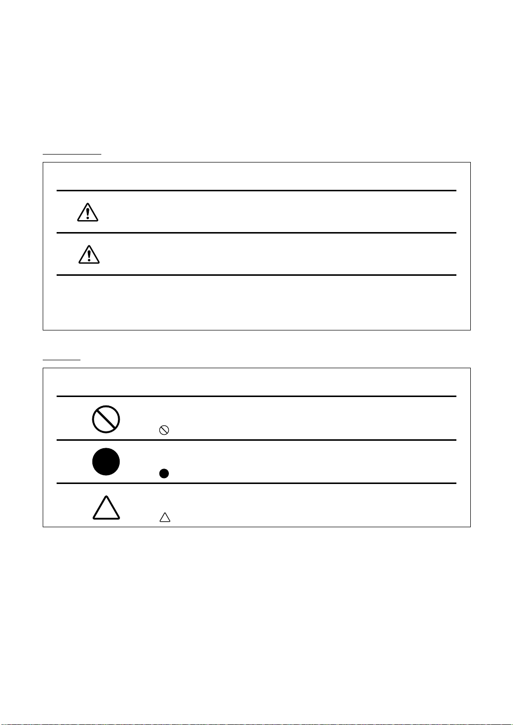
DISPLAYS
Display Meaning
WARNING
CAUTION
• Injury refers to hurt, cuts, bruises, electric shock, etc. which does not require hospitalization or extended medical treatment.
• Physical damage refers to extensive damage to the building, nearby equipment and/or
surrounding furniture.
Incorrect handling by ignoring this display may lead to an
impending danger of death or serious injury.
Incorrect handling by ignoring this display may lead to personal
injury or physical damage.
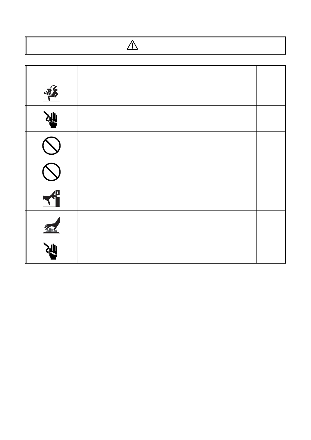
ICONS
Icon Meaning
Prohibition.
Specific content is expressed with words or a picture near the
icon.
Mandatory Action
Specific content is expressed with words or a picture near the
icon.
Caution
Specific content is expressed with words or a picture near the
icon.
4
Page 7
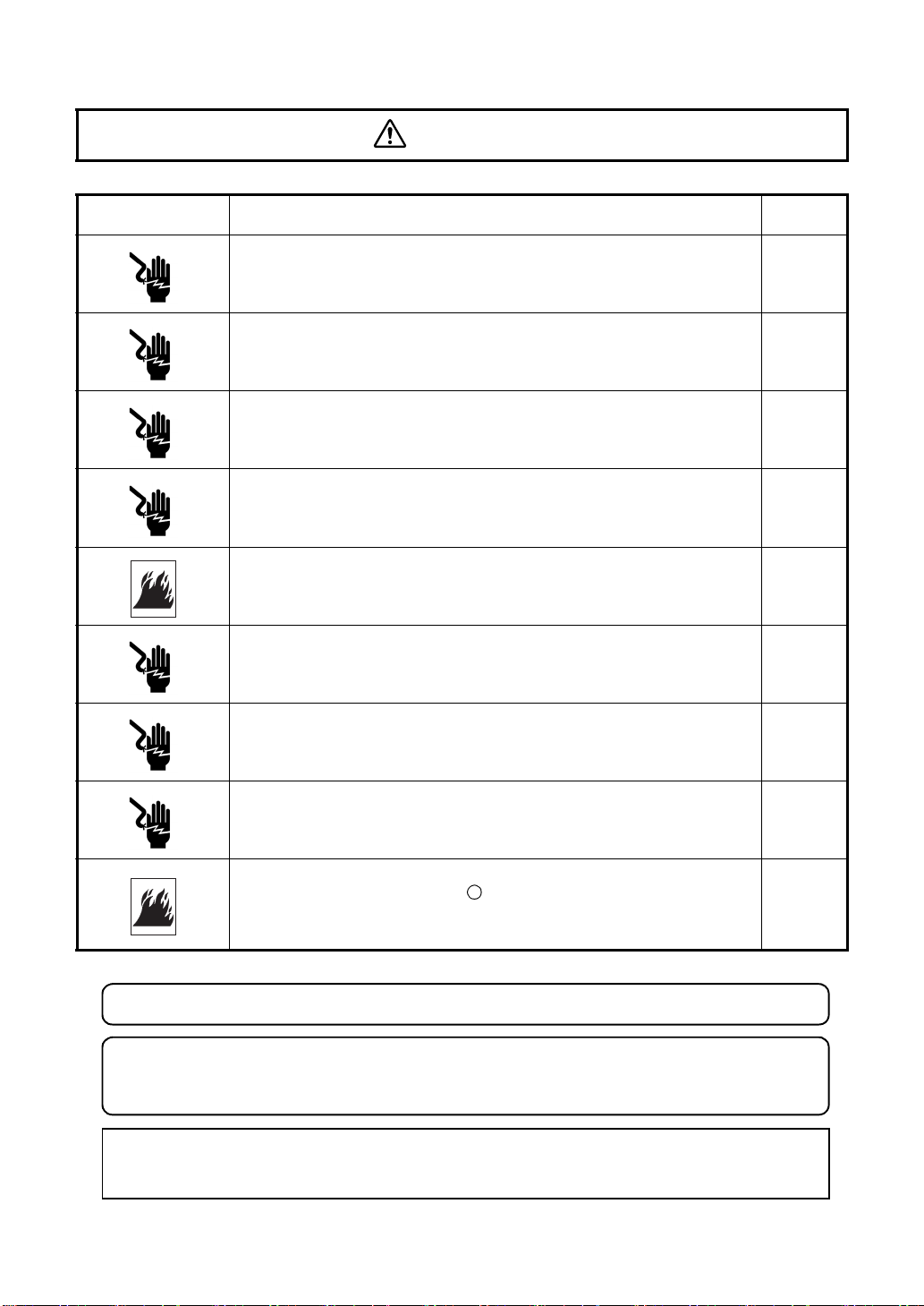
SAFETY CAUTIONS
Icon Prevention item Page
WARNINGS
To avoid fire and electric shock in case of leakage, be sure to use
a grounded outlet. Do not connect to outlets that are not grounded.
To avoid electric shock, do not attempt disassembling, rebuilding
and/or repairs on your own. Ask your dealer for repairs.
Do not remove the covers from the main unit, chinrest unit or
power supply unit except for the lamp house cover. You may
receive an electric shock.
To avoid electric shock, unplug the power cord from the grounded
outlet before removing the fuse cover. Do not connect the power
cord to the grounded outlet with the fuse cover left unfixed.
To avoid fire in the event of an instrument malfunction, use only
fuses that are fitted to the marked label at the side of the fuse
holder.
To avoid fire and electric shock, install the instrument in a dry
place free of water and other liquids.
To avoid fire and electric shock, do not put cups or other containers with liquids near the instrument.
22
62
62
75
75
-----
-----
To avoid electric shock, do not insert metal objects into any vents
and/or slots.
To avoid fire in the event of an instrument malfunction, immediately
turn OFF the power switch " " and unplug the cable if you see
smoke coming from the instrument, etc. Ask your dealer for service.
CAUTION : Federal laws restricts this device to the sale by or on the order of a physician.
WARNING : Handling the cord on this product or cords associated with accessories sold
with this product, will expose you to lead, a chemical known to the State of California to
cause birth detects or other reproductive harm. Wash hands after handling.
This Product Contains Mercury in the backlighting of the LCD display. Prior to disposal
remove of otherwise ensure that this is disposed of in accordance with Local, State and
Federal Laws. This information is applicable in U.S.A only.
-----
-----
5
Page 8
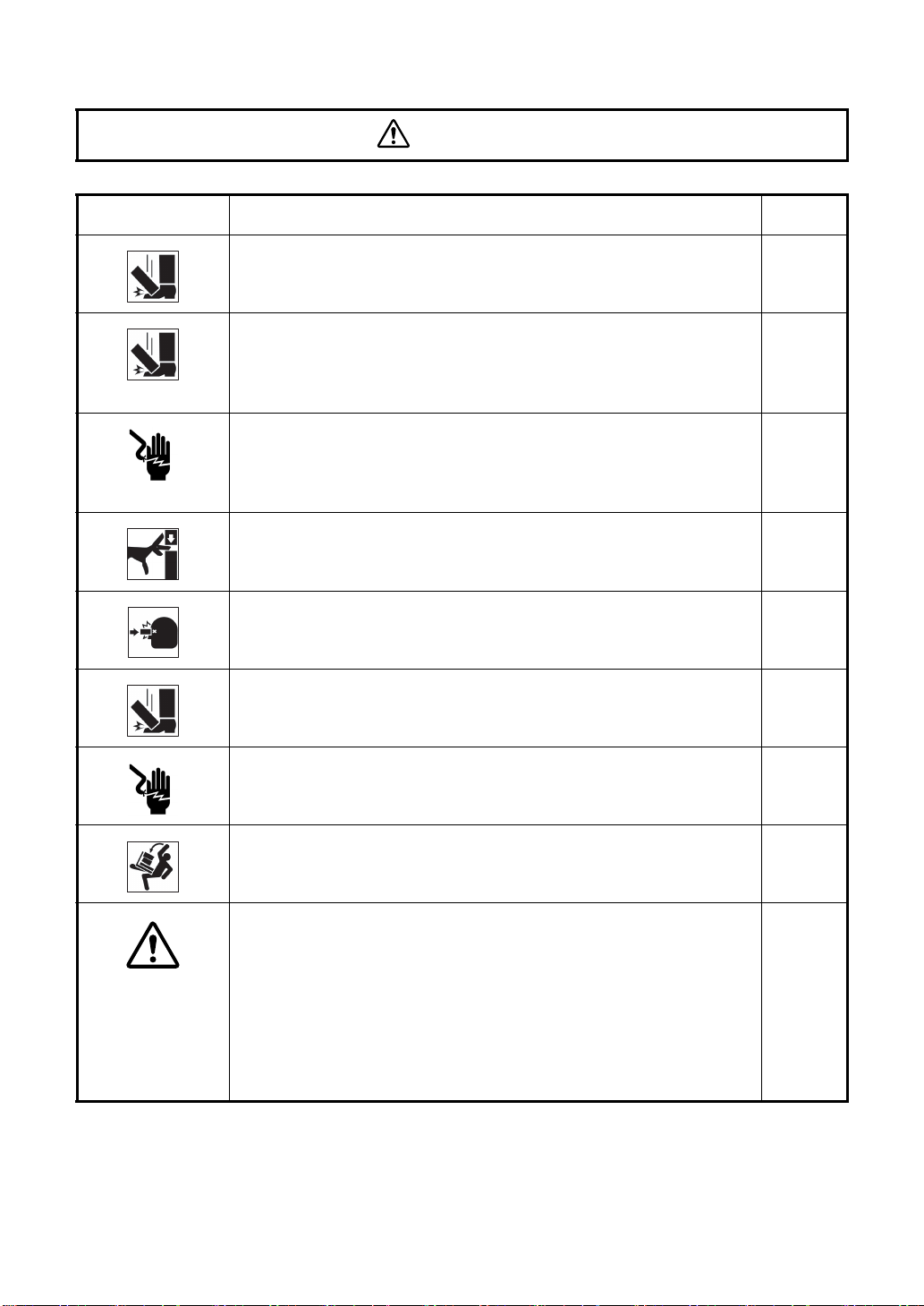
SAFETY CAUTIONS
Icon Prevention item Page
CAUTIONS
To prevent damage and injuries, do not install the instrument on an
uneven, unsteady or sloping surface.
To avoid electric shock, do not handle the plugs with wet fingers.
To avoid pain and discomfort to the patient and damage to the
patient’s eye, do not brighten the illumination lamp more than necessary.
To avoid pain and discomfort to the patient and damage to the
patient's eye, do not brighten the photography light more than necessary.
To avoid injury while moving the instrument, do not place your fingers into the gap between the instrument body and the power supply unit.
To avoid burns, allow lamp to cool before touching.
To avoid electric shock, do not touch the xenon lamp immediately
after it flashes or burns out.
18, 70
22
38
39
41
72
73
6
Page 9
SAFETY CAUTIONS
Icon Prevention item Page
CAUTIONS
Before transporting this instrument, secure the fixing knob on the
bottom to prevent movements.
This instrument should be carried by two persons. Carrying by
one person may cause backache or injury. Holding at areas other
than the bottom may also cause injury, as well as falling, thereby
damaging the instrument.
To avoid electric shock, unplug the power cord from the outlet
before assembling.
Do not plug the power cord into the outlet before assembling the
instrument.
To avoid injury to the patient's face and hands, be sure to operate
the chinrest for height adjustment while directly watching the
patient.
To avoid injury to the patient's eyes and nose while moving the
instrument body, keep a safe distance between the patient and the
objective lens.
To avoid injury by falling off, make sure that the digital camera is
correctly installed.
To avoid electric shock, be sure to turn the power switch off and
unplug the power cord before replacing the lamp.
18
18
18
36
41
70
72, 73
Always place and transport the instrument on a suitable instrument table.
This instrument has been tested (with 100/120/230V) and found to
comply with IEC60601-1-2: Ed.2.1: 2004.
This instrument radiates radio frequency energy within standard
and may affect other devices in the vicinity.
If you have discovered that turning on/off the instrument affects
other devices, we recommend you change its position, keep a
proper distance from other devices, or plug it into a different outlet.
Please consult your authorized dealer if you have any additional
questions.
-----
-----
7
Page 10

USAGE AND MAINTENANCE
Usage:
• The TRC-NW8 NON-MYDRIATIC RETINAL CAMERA is an electric instrument for medical
use. Use it accordingly.
USER MAINTENANCE
To ensure the safety and performance of the instrument, all maintenance work, unless specified in this manual, shall only be conducted by trained service engineers.
The following maintenance tasks may be done by the user.
For details, see the relevant part of this manual.
Replacing lamps:
The illumination lamp and xenon lamp may be replaced by the user. For details, see "Replacing the illumination lamp" on page 72 and "Replacing the xenon lamp" on page 73.
Replacing fuses:
Fuses of the instrument body may be replaced by the user. For details, see "Changing the
fuse" on page 75.
Cleaning the objective lens:
The objective lens may be cleaned by the user. For details, see "Cleaning the objective lens"
on page 79.
ESCAPE CLAUSES
• TOPCON shall not take any responsibility for damage due to fire, earthquakes, actions
by third persons and other accidents, or damage due to negligence and misuse by the
user and any use under unusual conditions.
• TOPCON shall not take any responsibility for damage derived from inability to properly
use this instrument, such as loss of business profit and suspension of business.
• TOPCON shall not take any responsibility for damage caused from using this instrument in a manner other than that described in this Instruction Manual.
• Diagnoses made shall be the responsibility of pertaining doctors and TOPCON shall not
take any responsibility for the results of such diagnoses.
8
Page 11
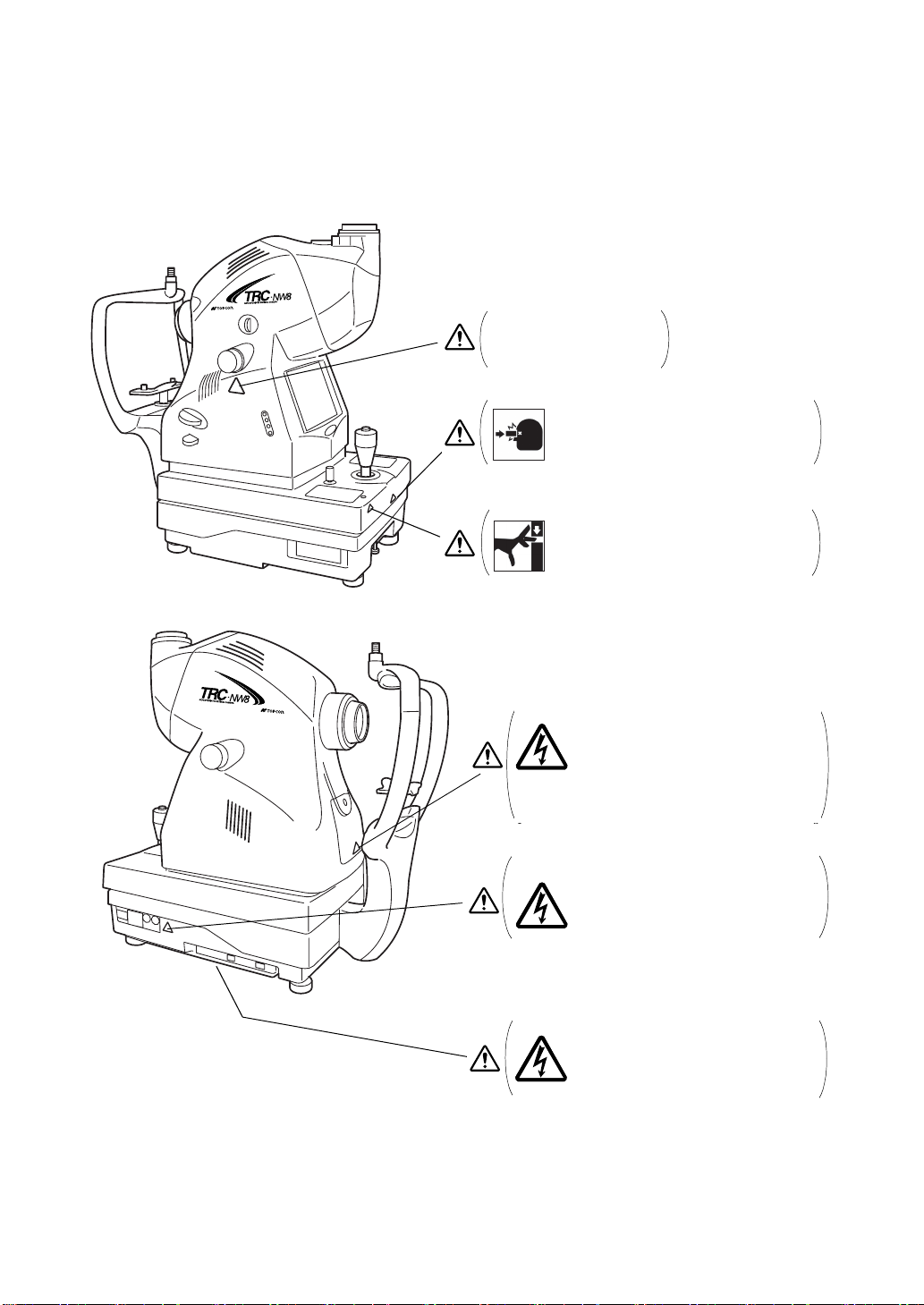
WARNING DISPLAYS AND POSITIONS
To ensure safety, this machine provides warning displays.
Use the instrument correctly by observing the display instructions. If any of the following display labels are missing, contact your TOPCON dealer at the address listed on the back cover.
CAUTION
Do not touch the focusing
knob while in auto focus
mode. You may be injured.
Be careful not to hit the patient's eyes or nose
with the instrument during operation.
CAUTION
CAUTION
When operating the chinrest switch, be careful not to pinch the patient's hand. The patient
may be injured.
CAUTION
y To avoid electric shock, turn off the
power switch when replacing the lamp.
y To avoid burns, do not replace the lamp
with a new one immediately after it goes
off because it is still very hot and can
cause burns.
WARNING
To avoid electric shock, turn off the power
switch and unplug the power cord and then
replace the lamp with a rated one.
To avoid injury caused by electric shock,
WARNING
do not open the cover. Ask your dealer for
service.
9
Page 12

CONTENTS
INTRODUCTION .................................................................................................................1
CAUTIONS FOR USE ......................................................................................................... 2
ENVIRONMENTAL CONDITIONS FOR USE .....................................................................2
STORAGE, USAGE PERIOD AND OTHERS .....................................................................2
ENVIRONMENTAL CONDITIONS FOR PACKAGING IN TRANSPORTATION ................. 3
CHECKPOINTS FOR MAINTENANCE ...............................................................................3
DISPLAY FOR SAFE USE .................................................................................................. 4
SAFETY CAUTIONS ........................................................................................................... 5
USAGE AND MAINTENANCE ............................................................................................. 8
ESCAPE CLAUSES ............................................................................................................. 8
WARNING DISPLAYS AND POSITIONS ............................................................................9
NOMENCLATURE
COMPONENT NAMES ......................................................................................................12
COMPOSITION OF PARTS THAT COME IN CONTACT WITH THE PATIENT ............... 12
CONTROL PANEL COMPONENTS ..................................................................................13
COMPONENTS ON COLOR LCD MONITOR SCREEN ................................................... 15
STANDARD ACCESSORIES ............................................................................................ 17
PREPARATIONS
ASSEMBLY PROCEDURE OF THE INSTRUMENT BODY ..............................................18
INSTALLING THE DIGITAL CAMERA .............................................................................. 20
HOW TO CONNECT THE CABLES .................................................................................. 20
CONFIRMATION AFTER ASSEMBLY ..............................................................................21
CONNECTING THE POWER CORD ................................................................................ 22
CONNECTING THE EXTERNAL DEVICE ........................................................................23
MENU SETTING ................................................................................................................24
SETTING THE RECORDING MEDIUM TO SAVE IMAGE ...............................................30
RESET FROM POWER SAVE STATE ..............................................................................34
BASIC OPERATIONS
FLOW OF OPERATION .................................................................................................... 35
OTHER TYPES OF PHOTOGRAPHY ...............................................................................35
PREPARATION FOR PHOTOGRAPHY ............................................................................ 36
COLOR PHOTOGRAPHY (CENTER) ............................................................................... 38
EXITING .............................................................................................................................46
OBJECTIVE OPERATIONS
PERIPHERAL PHOTOGRAPHY ....................................................................................... 47
SMALL PUPIL PHOTOGRAPHY .......................................................................................51
RED-FREE PHOTOGRAPHY WITH RF FILTER .............................................................. 54
ANTERIOR SEGMENT PHOTOGRAPHY ......................................................................... 55
STEREO PHOTOGRAPHY ...............................................................................................57
IMAGE PLAYBACK MODE ................................................................................................ 59
BEFORE REQUESTING SERVICE
TROUBLESHOOTING .......................................................................................................61
SPECIFICATIONS & PERFORMANCE
10
Page 13

SPECIFICATIONS .............................................................................................................64
ELECTROMAGNETIC COMPATIBILITY ...........................................................................65
ELECTRIC RATING ...........................................................................................................68
SYSTEM CLASSIFICATION .............................................................................................. 68
DIMENSIONS AND WEIGHT ............................................................................................69
PURPOSE OF USE ........................................................................................................... 69
OPERATION PRINCIPLE ..................................................................................................69
MAINTENANCE
DAILY CHECKUPS ............................................................................................................ 70
CLEANING .........................................................................................................................79
OPTIONAL ACCESSORIES
EXTERNAL FIXATION TARGET EF-2 ..............................................................................81
REFERENCE MATERIAL
SHAPE OF PLUG ..............................................................................................................82
SYMBOL ............................................................................................................................82
USABLE AUTOMATIC INSTRUMENT TABLE ..................................................................82
RELATION BETWEEN SETTING OF ILLUMINATION/
FLASH LEVEL AND MAXIMUM RADIANCE
INFORMATION ABOUT THE OPTICAL RADIATION HAZARD TO THE USER ..............84
...................................................83
11
Page 14
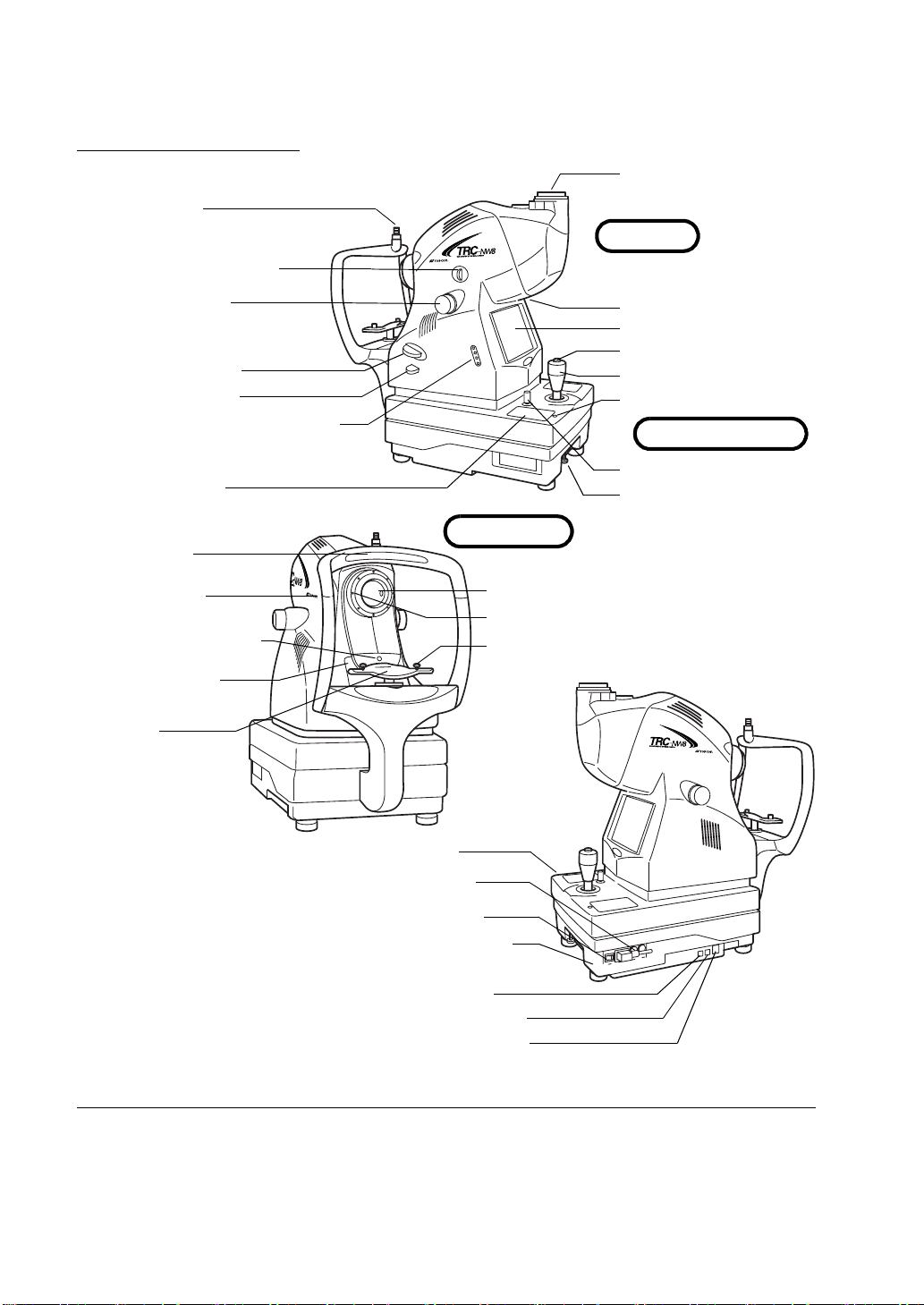
NOMENCLATURE
COMPONENT NAMES
Connector
Diopter compensation
lens selector
Focusing knob
RF filter selector
IR filter selector
Image quality adjustment switch
Camera mount
Main unit
LED illuminator
Color LCD monitor
Photography switch
Control lever
Power lamp
Power supply unit
Control panel
Forehead rest
Canthus marker
Lamp house cover screw
Lamp house cover
Chinrest
Base brake knob
Fixing knob (for carrying)
Chinrest unit
Objective lens
Anterior segment fixation target
Chinrest tissue pin
Base unit
Fuse holder
Power switch
Power supply unit
Image terminal
Image/data terminal
Input/output terminal
COMPOSITION OF PARTS THAT COME IN CONTACT WITH THE PATIENT
Forehead rest : Silicone rubber
Chinrest : Acrylonitrile butadiene styrene resin
Chinrest tissue pin : Polyamide resin
12
NOMENCLATURE
Page 15
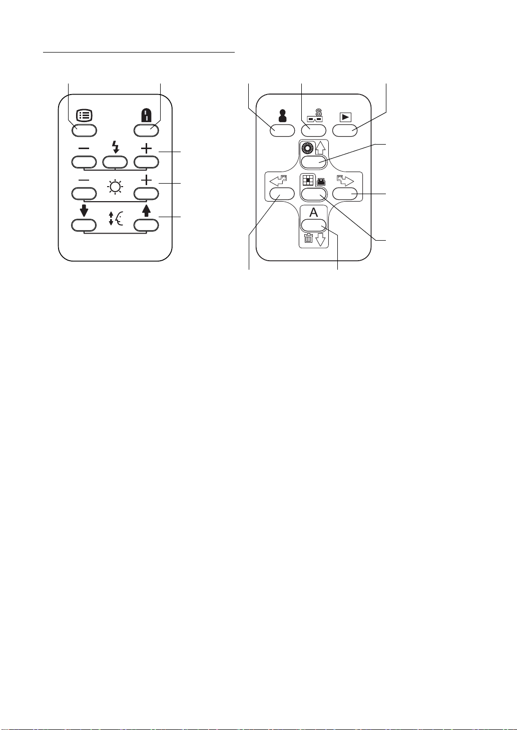
CONTROL PANEL COMPONENTS
Menu switch Split switch
ID input switch
Stereo photography switch
Image playback switch
Flash level switch
(-, reset, +)
Illumination level
switch (-, +)
Chinrest switch
(down, up)
Fixation target selector
switch (counterclockwise)
(Leftward cursor switch)
AUTO switch
(Downward cursor switch)
(Image deletion switch)
Illumination diaphragm
selector switch
(Upward cursor switch)
Fixation target selector
switch (clockwise)
(Rightward cursor
switch)
Fixation target selector
switch (reset)
(ENTER switch)
(PRINT switch)
Menu switch: P.24
Displays "MENU".
Split switch: P.44
Turns on/off the split line.
* (The function of the split switch can be changed by setting. For example, this switch can
be set in order to turn on/off the internal fixation target.)
Flash level switch: P.39
Adjusts the flash level according to the patient's eye condition.
Illumination level switch: P.38
Adjusts the illumination level according to the patient's eye condition.
Chinrest switch: P.37
Adjusts the chinrest up/down movement.
ID input switch: P.36
Moves to the ID input screen.
Image playback switch [Reading the image]: P.59
Reproduces the image stored in the set record media.
(This switch function is invalidated by the setting on the external recording device and the
instrument.)
Illumination diaphragm selector switch: P.51
(Upward cursor switch): P.24, P.36
Used in small pupil photography. IN/OUT of the illumination diaphragm for small pupil
(hereinafter, small pupil diaphragm) is done.
(You can move the selection cursor upward when entering the menu and ID.)
NOMENCLATURE
13
Page 16

AUTO switch: P.44
(Downward cursor switch): P.24, P.36
(Image deletion switch [Deleting the image]): P.60
Turns ON/OFF the auto shoot/auto focus/auto small pupil functions. (ON/OFF of each function can be set by "MENU".)
(You can move the selection cursor downward when entering the menu and ID. Turns ON/
OFF to delete the reviewed photographic image.)
Fixation target selector switch (counterclockwise): P.47
(Leftward cursor switch): P.36
Switches the position of the internal fixation target to guide the patient's eye to the periphery
fixation point.
(You can move the selection cursor leftward when entering the menu and ID.)
Fixation target selector switch (clockwise): P.47
(Rightward cursor switch): P.36
Switches the position of the internal fixation target to guide the patient's eye to the periphery
fixation point.
(You can move the selection cursor rightward when entering the menu and ID.)
Fixation target selector switch (reset): P.47
(ENTER switch): P.24, P.36
(PRINT switch): P. 59
Switches the current internal fixation target position to the first position.
(Turn ON this switch to print the reviewed image. Chooses the selected item in "MENU".)
Stereo photography switch: P.57
Shifts to the stereo photography mode.
* For details, contact your dealer or TOPCON (see the back cover).
14
NOMENCLATURE
Page 17
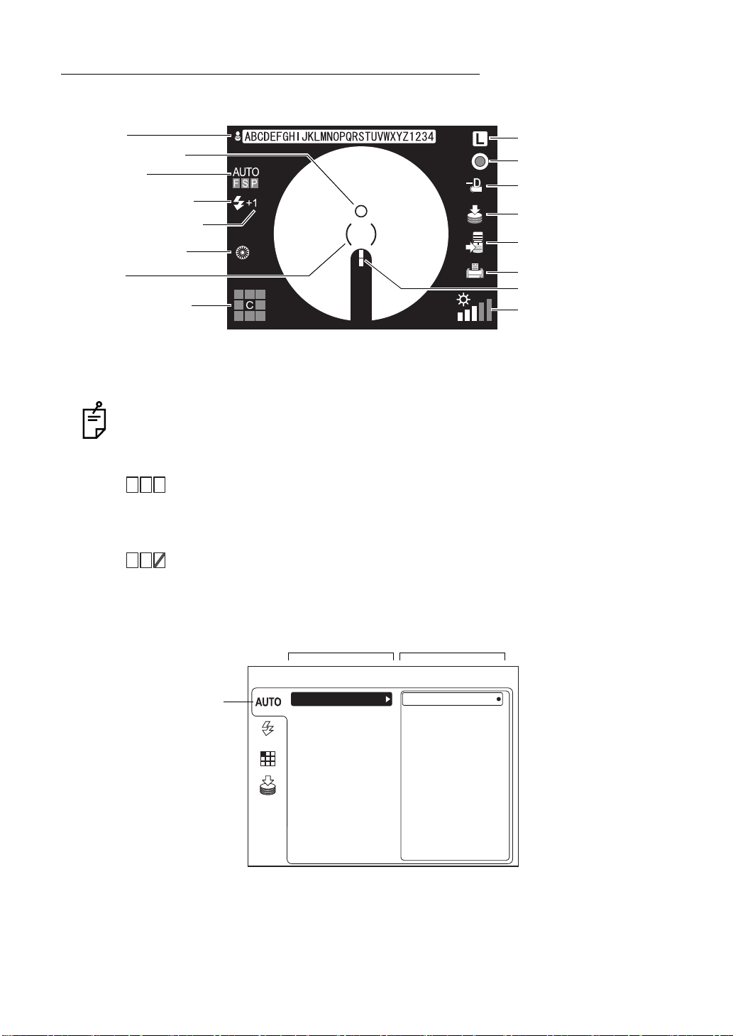
COMPONENTS ON COLOR LCD MONITOR SCREEN
Monitor screen
Patient ID
Alignment bright spot
AUTO display
Xenon charging display
Flash level compensation
Small pupil diaphragm
* ( ) scale
Fixation target position
Right/left eye
RF filter
Diopter compensation lens
display
USB memory recognition
display
External connection device
recognition display
Printer recognition display
Split lines
Illumination level
* When the ( ) scale blinks in red, pull the base toward you (the operator) to the limit. For mov-
ing the instrument, refer to page 41.
The AUTO display shows the auto function that is ON. For setting the auto functions,
refer to "MENU SETTING" on page 24.
AUTO
FSP
"F" is lit: The auto focus function is ON. (Set it to "OFF", and "F" is darkened.)
"S" is lit: The auto shoot function is ON. (Set it to "OFF", and "S" is darkened.)
"P" is lit: The auto small pupil function is ON. (Set it to "OFF", and "P" is dark-
ened.)
AUTO
FSP
When the auto function, which has been set to "ON", is invalidated, a red
oblique line is displayed.
The left figure shows that the auto small pupil function is invalidated.
MENU screen
FOCUS Icon
FLASH
FIXATION
MEMORY
Item to be set Contents to be set
MENU
FOCUS
SHOOT
SMALL PUPIL
ON
OFF
15
NOMENCLATURE
Page 18

Preview screen
Patient ID
AUTO display
Xenon charging display
Flash level compensation
Small pupil diaphragm
Fixation target position
Right/left eye
RF filter
Diopter compensation lens
display
Photographic image
Printer recognition display
16
NOMENCLATURE
Page 19
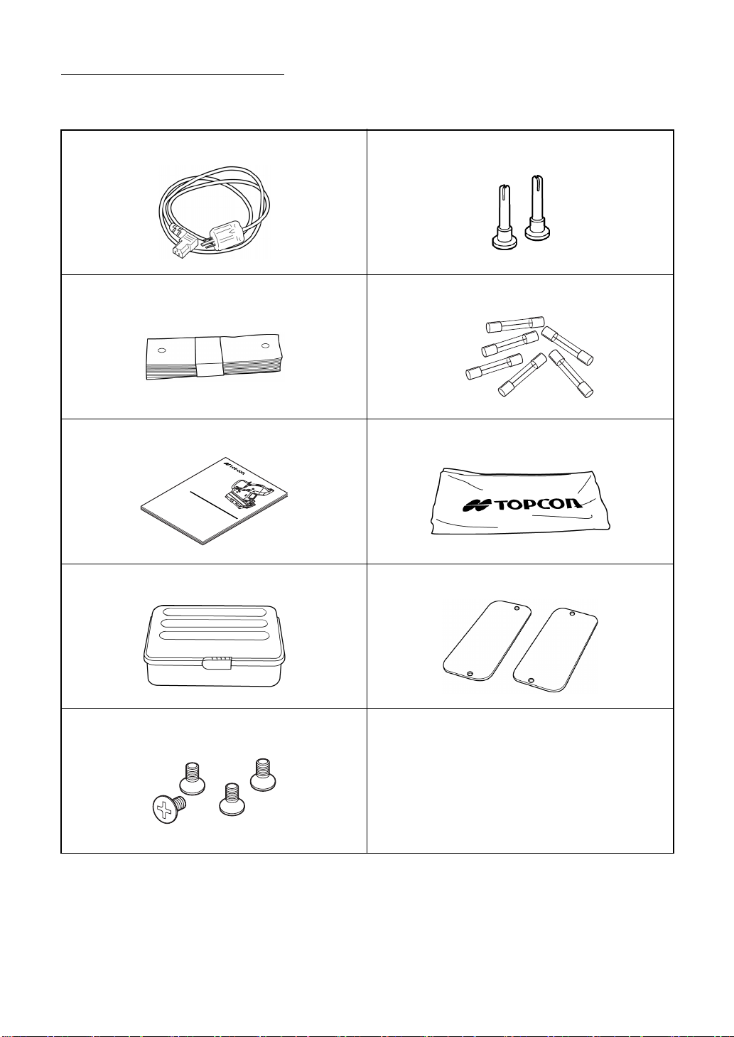
STANDARD ACCESSORIES
Upon unpacking, make sure that all the following standard accessories are included. Numbers
in ( ) are the quantities.
Power cord (1) Chinrest tissue pin (2)
Chinrest tissue paper (1) Fuse (6)
Instruction manual (1) Dust cover (1)
INSTRUCTION MANUAL
NON-MYDRIATIC RETINAL CAMERA
TRC-NW8
Spare parts case (1) Rail cover (2)
Screw (4)
17
NOMENCLATURE
Page 20
PREPARATIONS
ASSEMBLY PROCEDURE OF THE INSTRUMENT BODY
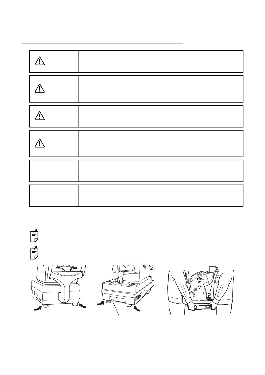
CAUTION
CAUTION
CAUTION
CAUTION
NOTE
NOTE
Before transporting this instrument, secure the fixing knob on the bottom to prevent movements.
This instrument should be carried by two persons. Carrying by one
person may cause backache or injury. Holding at areas other than the
bottom may also cause injury, as well as falling, thereby damaging the
instrument.
To prevent damage and injuries, do not install the instrument on an
uneven, unsteady or sloping surface.
To avoid electric shock, unplug the power cord from the outlet before
assembling.
Do not plug the power cord into the outlet before assembling the
instrument.
Since the upper part and lower part of the instrument body are merely
connected to each other with the power cable, take them out together
so they do not separate from each other.
Always place the instrument in the center of the instrument table.
1 Take out the instrument body from the cardboard box and put it on the table.
Before transporting, make sure that the back-and-forth and right-and-left movement of the
base stops because of the fixing knob. If the base moves, turn the fixing knob to stop it.
When carrying the instrument body, firmly hold it at the following specified positions.
Holding positions
Fixing knob
Holding the instrument body
2 Loosen the fixing knob.
18
PREPARATIONS
Page 21
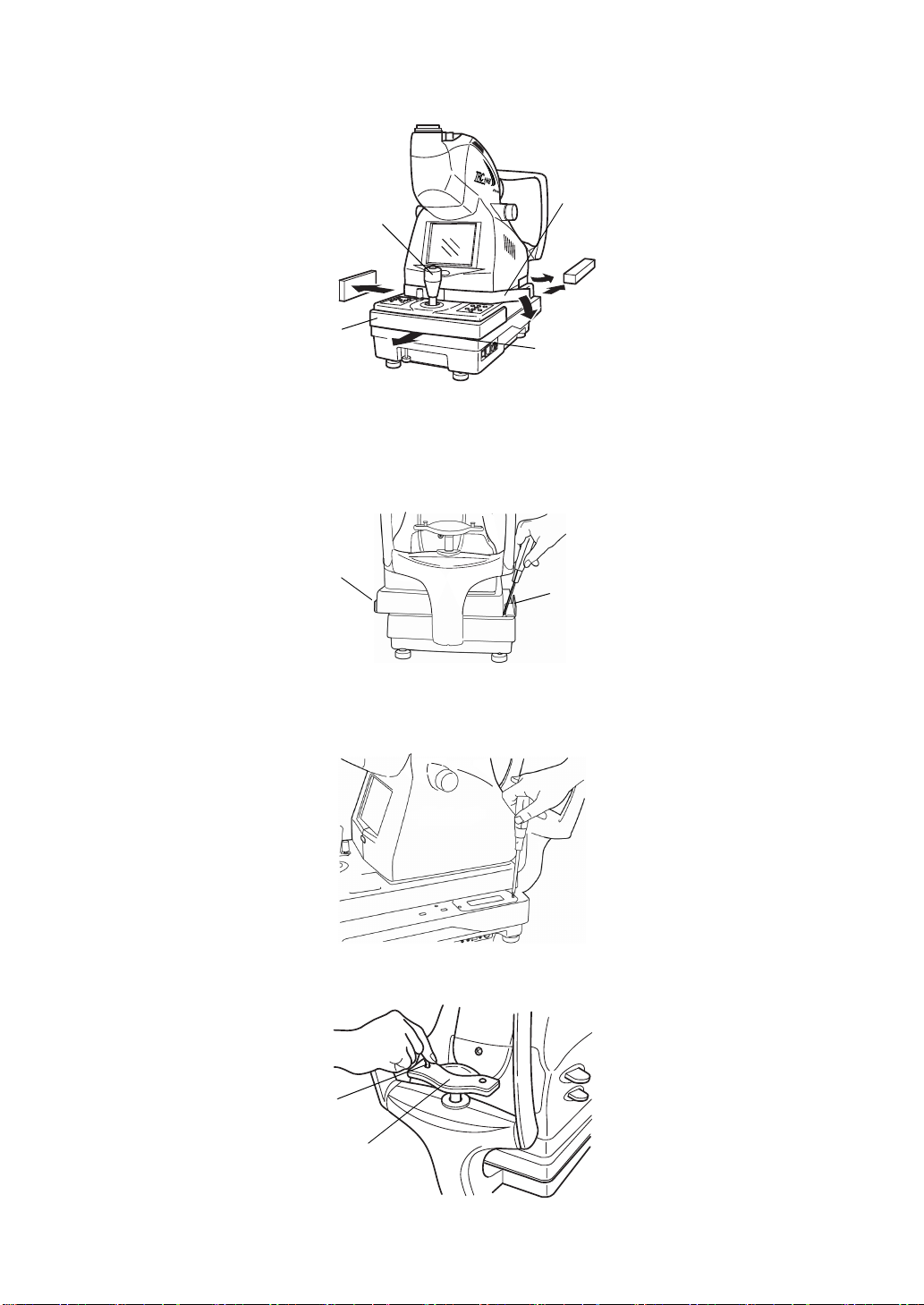
3 Slightly raise the control lever and take out the cushion from the lower part of the base in
the arrow direction.
Sponge
Control lever
Sponge
Cushion
Sliding board
(between the instrument body and base unit)
Styrofoam
4 Wipe the sliding board with a cloth, etc. to remove dust.
5 Remove the styrofoam from the transportation bracket (A) (the one on the left hand side as
viewed from the chinrest side,), slide the base to the left and unscrew the transportation
bracket (B).
Transportation bracket (A)
Transportation bracket (B)
6 Slide the base to the right and unscrew the transportation bracket (A) with the screwdriver.
7 Fasten the rail covers, using the small screws that are attached.
8 Affix the chinrest tissue paper with the chinrest tissue pin.
Chinrest tissue pin
Chinrest tissue paper
19
PREPARATIONS
Page 22
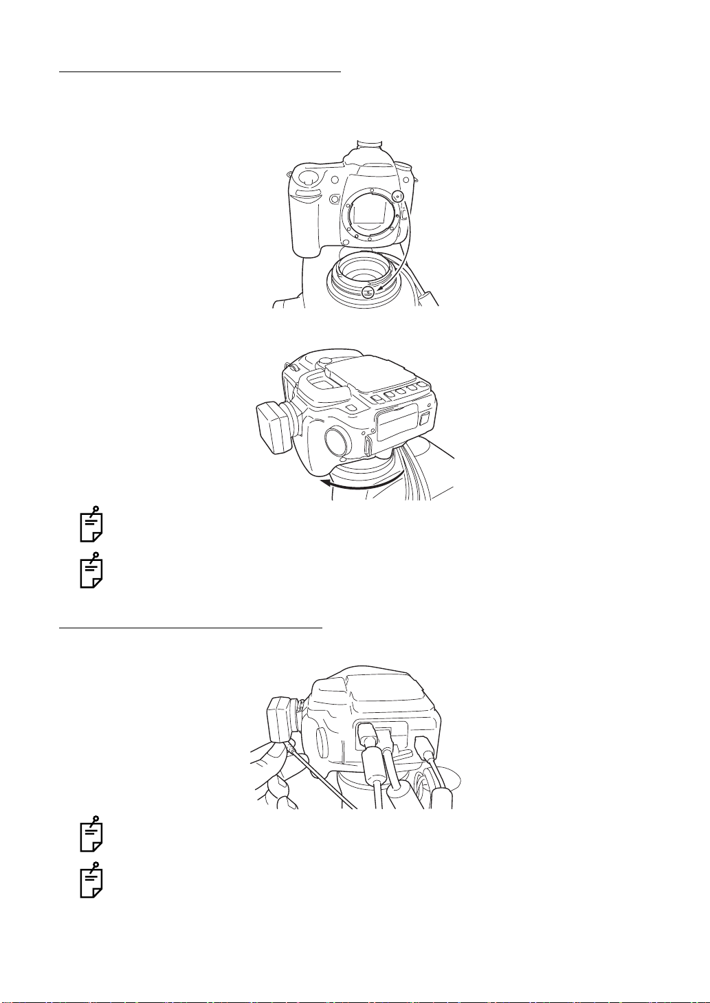
INSTALLING THE DIGITAL CAMERA
1 Remove the cap from the digital camera to be installed.
2 Align the positioning mark of the instrument with the mark on the digital camera's mount.
3 Turn the digital camera clockwise until a "click" is heard.
When taking out the digital camera from the instrument, turn the digital camera counterclockwise while pressing its lens lock release button.
For some types of the digital cameras to be installed, a mount conversion adapter or tele
converter is necessary.
HOW TO CONNECT THE CABLES
Connect the cables for the digital camera, which come out of the instrument.
When connecting the cables, refer to the instruction manual of the digital camera.
If you have a question about the digital camera, contact your dealer or TOPCON (listed
on the back cover).
20
PREPARATIONS
Page 23
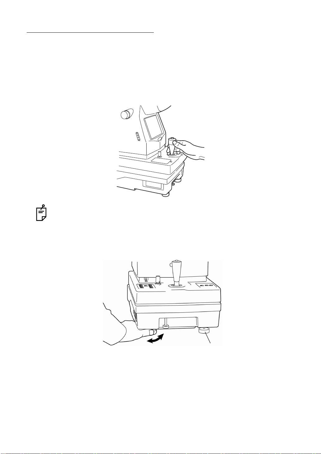
CONFIRMATION AFTER ASSEMBLY
1 Make sure that the input voltage is within ±10% of the rated voltage for the instrument.
If the input voltage exceeds this range, use a constant-voltage power supply (marketed:
400VA or more).
2 Loosen the base brake knob, and move the control lever to verify that it moves smoothly.
1) Right-left movement
2) Back-forth movement
3) Up-down movement
Just after being unpacked, the right-left movement may be uneven. If so, move the control lever with force to its limits in all directions.
3 If the instrument body is slightly off level, finely adjust the height by properly turning the
four adjusters.
Do not extend the adjusters past 1cm.
Adjuster
21
PREPARATIONS
Page 24
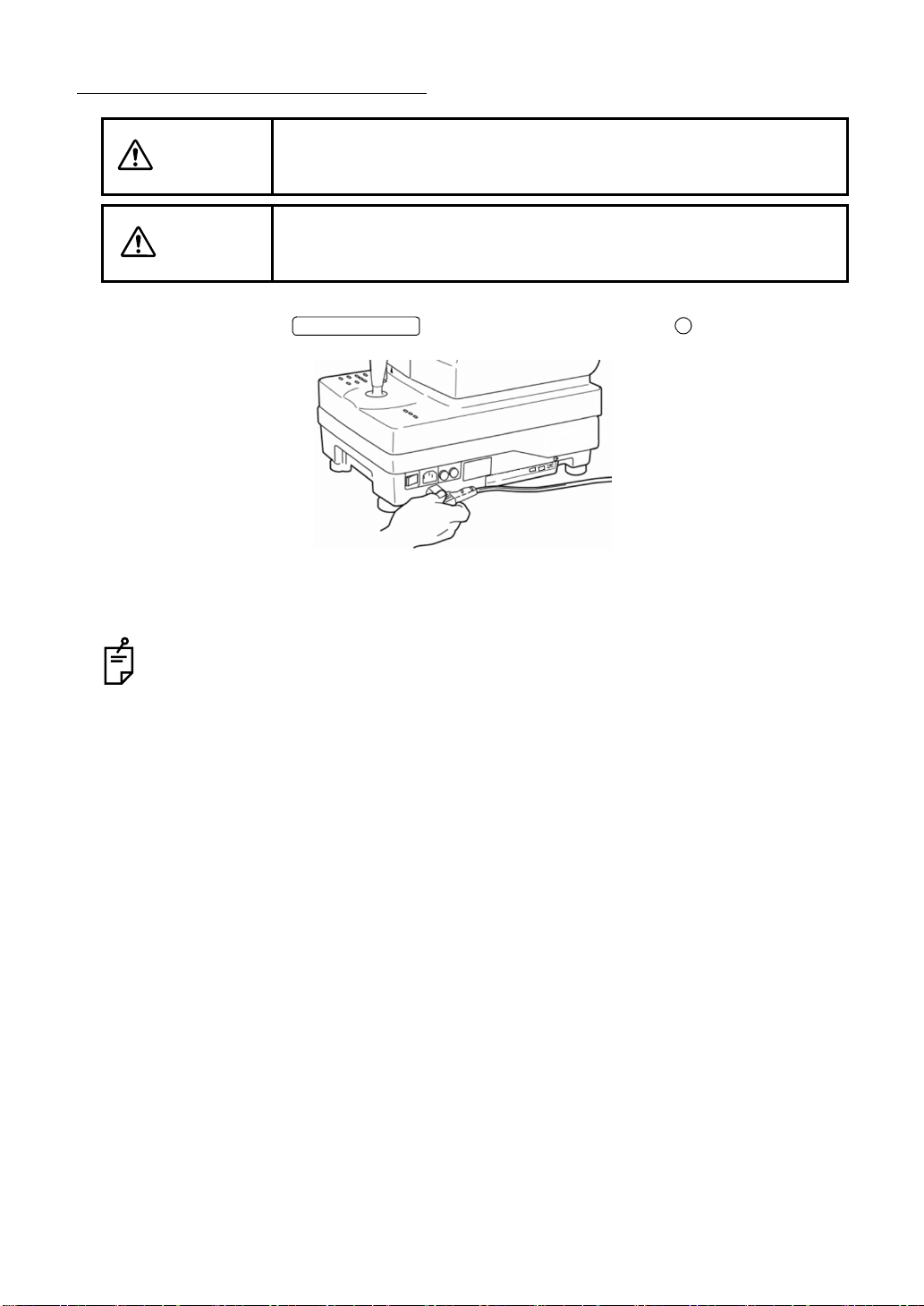
CONNECTING THE POWER CORD
WARNING
CAUTION
1 Make sure that the of the instrument body is OFF ( ).
To avoid fire and electric shock in case of leakage, be sure to use a
grounded outlet. Do not connect to outlets that are not grounded.
To avoid electric shock, do not handle the plugs with wet fingers.
POWER SWITCH
2 Attach the power cord to the instrument body.
3 Plug the power cord into a proper outlet with grounding.
Refrain from using UPS (Uninterruptible Power Supply). The trouble caused by using
UPS will not be guaranteed.
22
PREPARATIONS
Page 25
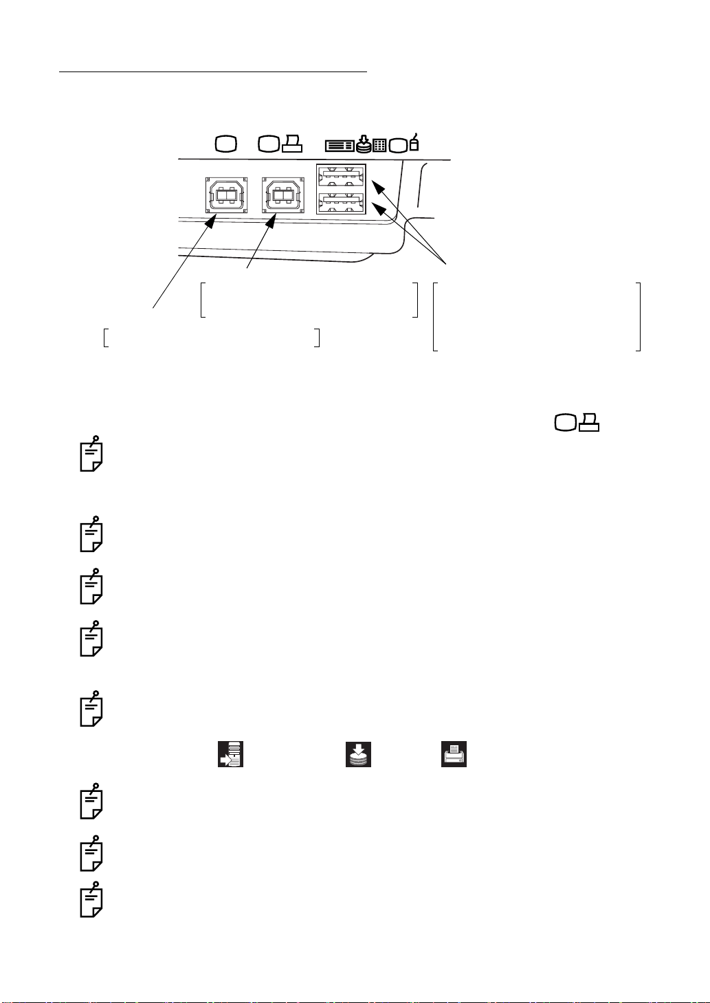
CONNECTING THE EXTERNAL DEVICE
This instrument can be connected to an image filing system such as IMAGEnet (commercial
product), etc.
Image/data terminal Input/output terminal
Image filing system (commercial product)
Digital printer (commercial product)*
Image terminal
Image filing system (commercial product)
* By connecting the digital printer applicable to Pict Bridge, direct print is done.
Connecting to IMAGEnet (commercial product), etc.
Recording device (commercial product)
Data input device (commercial product)
Ten key board (commercial product)
Keyboard (commercial product)
Mouse (commercial product)
1 Connect one USB cable (commercial product) to the image/data terminal .
Be sure to connect IMAGEnet (commercial product), etc. to the image/data terminal.
2 Connect the other end of the USB cable to IMAGEnet, etc.
Use the external device complying with IEC60950/IEC60950-1 or UL60950/UL60950-1.
For details about connecting the external devices, contact your dealer or TOPCON (see
the back cover).
To increase the image transfer speed, connect IMAGEnet, etc. with two USB cables
(commercial products). In this case, the photographed image is not displayed on the
color LCD monitor. For details, contact your dealer or TOPCON (see the back cover).
When connecting the external device, do not take a picture before the recognition displays shown below appear on the color LCD monitor.
Personal computer: USB memory: Printer:
When you want to change the date stored in the recording device, contact your dealer or
TOPCON office (see the back cover).
Before using the USB memory, make sure that it is not infected with the computer virus.
Then, connect it.
For the use of an image filing system such as IMAGEnet, etc., refer to the instruction
manual of each system.
23
PREPARATIONS
Page 26
MENU SETTING
In menu setting, ON/OFF of the auto functions, the flash level and the fixation target can be
set.
Preparations for menu setting
1 Check the power cord connections.
For details about the connection, see "CONNECTING THE POWER CORD" on page 22.
2 Turn the ON (I).
POWER SWITCH
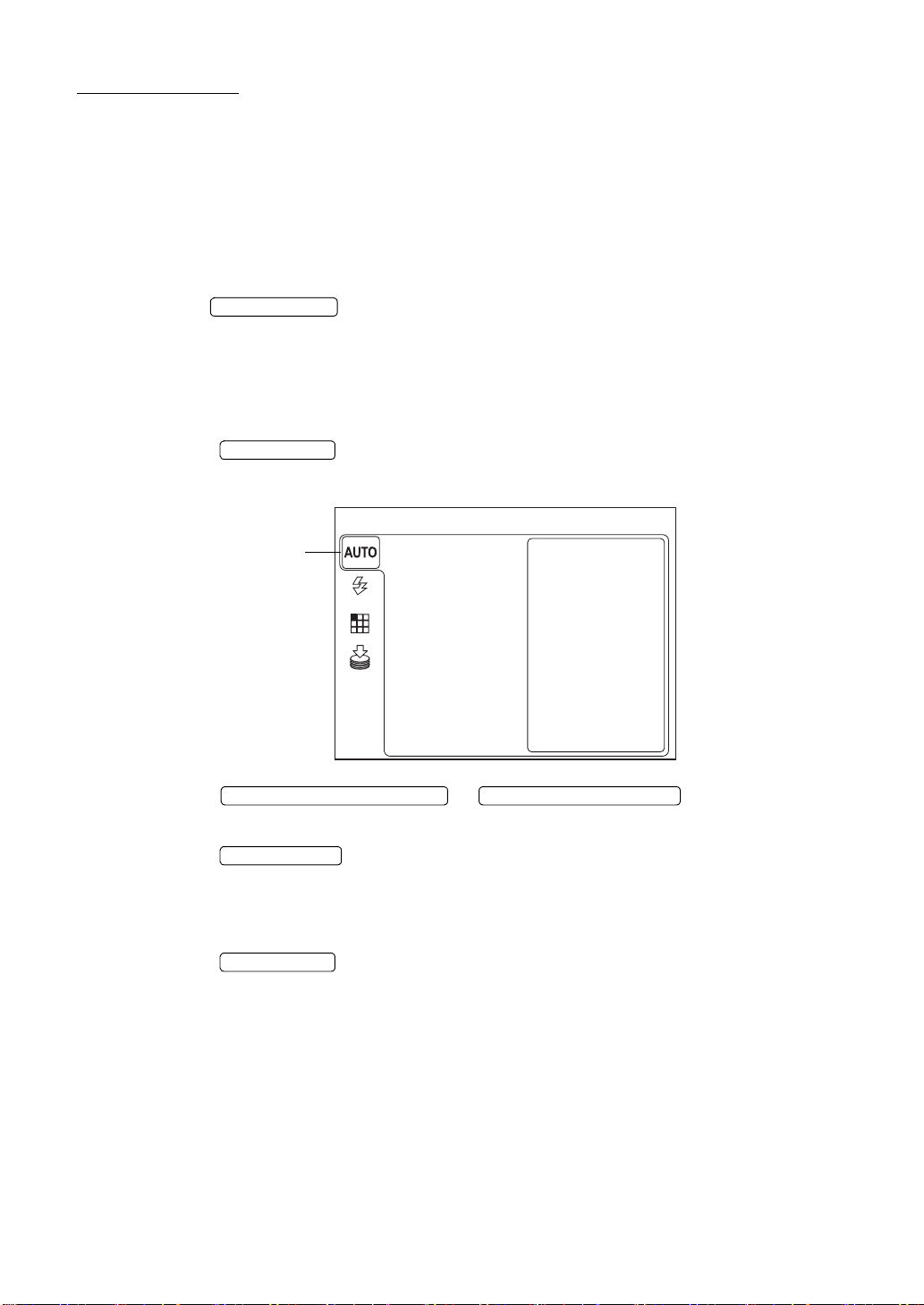
Displaying the menu screen
1 Make sure that the Monitor screen is displayed.
2 Press the on the control panel.
Make sure that "MENU" is displayed.
The color of the selected
icon is changed.
3 Press the or ; the selected item is
changed.
MENU SWITCH
MENU
FOCUS
SHOOT
SMALL PUPIL
FLASH
FIXATION
MEMORY
DOWNWARD CURSOR SWITCH UPWARD CURSOR SWITCH
4 Press the , and the selected item is chose.
ENTER SWITCH
Returning to the Monitor screen
1 Press the .
MENU SWITCH
24
PREPARATIONS
Page 27
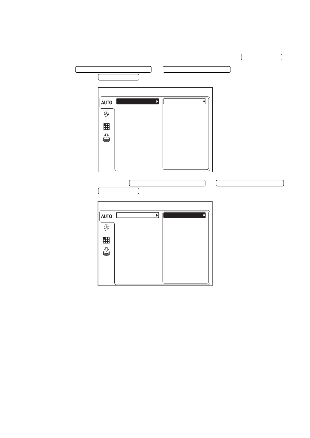
Setting of auto focus
Set the auto focus function ON/OFF. (When shipped, "ON" is set.)
When auto focus is set to ON, focusing is automatically done when taking a picture.
1 On the "MENU" screen, make sure that "AUTO" is selected and press the .
2 Press the or to select "FOCUS"
and then press the .
3 Select "ON" or "OFF" with the or
and then press the . The selected data is set.
DOWNWARD CURSOR SWITCH UPWARD CURSOR SWITCH
ENTER SWITCH
MENU
FOCUS
SHOOT
SMALL PUPIL
FLASH
FIXATION
MEMORY
DOWNWARD CURSOR SWITCH UPWARD CURSOR SWITCH
ENTER SWITCH
FOCUS
SHOOT
SMALL PUPIL
FLASH
ON
OFF
MENU
ON
OFF
ENTER SWITCH
FIXATION
MEMORY
25
PREPARATIONS
Page 28

Setting of auto shoot
Set the auto shoot function ON/OFF. (When shipped, "ON" is set.)
The auto shoot mechanism works as follows: when the fitted alignment bright spot is put into
( ) in the focalized status, the instrument takes a picture automatically without pressing the
photography switch.
1 On the "MENU" screen, make sure that "AUTO" is selected and press the .
2 Press the or to select "SHOOT"
and then press the .
3 Select "ON" or "OFF" with the or
and then press the . The selected data is set.
DOWNWARD CURSOR SWITCH UPWARD CURSOR SWITCH
ENTER SWITCH
MENU
FOCUS
SHOOT
SMALL PUPIL
FLASH
FIXATION
MEMORY
DOWNWARD CURSOR SWITCH UPWARD CURSOR SWITCH
ENTER SWITCH
FOCUS
SHOOT
SMALL PUPIL
FLASH
ON
OFF
MENU
ON
OFF
ENTER SWITCH
26
PREPARATIONS
FIXATION
MEMORY
Page 29

Setting of auto small pupil
Set the auto small pupil function ON/OFF. (When shipped, "ON" is set.)
The auto small pupil mechanism works as follows: when the pupil diameter of the patient is too
small to take a picture, the instrument automatically changes to the small pupil diaphragm.
1 On the "MENU" screen, make sure that "AUTO" is selected and press the .
2 Press the or to select "SMALL
PUPIL" and then press the .
3 Select "ON" or "OFF" with the or
and then press the . The selected data is set.
DOWNWARD CURSOR SWITCH UPWARD CURSOR SWITCH
ENTER SWITCH
MENU
FOCUS
SHOOT
SMALL PUPIL
FLASH
FIXATION
MEMORY
DOWNWARD CURSOR SWITCH UPWARD CURSOR SWITCH
ENTER SWITCH
FOCUS
SHOOT
SMALL PUPIL
FLASH
ON
OFF
MENU
ON
OFF
ENTER SWITCH
FIXATION
MEMORY
27
PREPARATIONS
Page 30

Switching of internal/external fixation targets (The external fixation target is an
optional accessory.)
You can change the internal/external fixation targets.
When shipped, "INTERNAL" (internal fixation target) is set.
1 Select "FIXATION" on the "MENU" screen and press the .
ENTER SWITCH
MENU
INT / EXT
TYPE
MODE
FLASH
PERIPHERAL
DCF
FIXATION
MEMORY
2 Press the or to select "INT/EXT"
and then press the .
DOWNWARD CURSOR SWITCH UPWARD CURSOR SWITCH
ENTER SWITCH
MENU
EXTERNAL
INTERNAL
FLASH
FIXATION
INT / EXT
TYPE
MODE
PERIPHERAL
DCF
MEMORY
3 Press the or to select "INTER-
DOWNWARD CURSOR SWITCH UPWARD CURSOR SWITCH
NAL" (internal fixation target) or "EXTERNAL" (external fixation target). Then, press the
ENTER SWITCH
.
MENU
EXTERNAL
INTERNAL
FLASH
FIXATION
MEMORY
INT / EXT
TYPE
MODE
PERIPHERAL
DCF
28
PREPARATIONS
Page 31

Fixation target pattern
You can select the fixation target pattern.
When shipped, "8POINT" is set.
1 Move the cursor to "FIXATION" on the "MENU" screen, and press the .
ENTER SWITCH
MENU
INT / EXT
TYPE
MODE
FLASH
PERIPHERAL
DCF
FIXATION
MEMORY
2 Press the or to select "PERIPH-
ERAL" and then press the .
DOWNWARD CURSOR SWITCH UPWARD CURSOR SWITCH
ENTER SWITCH
MENU
4A
4B
5A
5B
8POINT
9POINT
FLASH
FIXATION
INT / EXT
TYPE
MODE
PERIPHERAL
DCF
FIXATION PATTERN
MEMORY
3 Press the or and select the
DOWNWARD CURSOR SWITCH UPWARD CURSOR SWITCH
desired pattern from the following:
"4A" (diagonal 4 positions),
"4B" (vertical-horizontal 4 positions),
"5A" (diagonal 4 positions + center),
"5B" (vertical-horizontal positions + center),
"8POINT" (8 positions), or
"9POINT" (8 positions + center).
Press the .
ENTER SWITCH
FLASH
FIXATION
MEMORY
INT / EXT
TYPE
MODE
PERIPHERAL
DCF
FIXATION PATTERN
MENU
4A
4B
5A
5B
8POINT
9POINT
For setting and lighting the internal fixation target, refer to "MEMO" on page 48.
29
PREPARATIONS
Page 32

SETTING THE RECORDING MEDIUM TO SAVE IMAGE
Set the recording medium to save the photographed image.
When saving the image in the USB memory (commercial product), etc.
It is not necessary to set some items on "MENU". Connect the recording device such as the
USB memory (hereinafter, USB memory) to the input/output terminal. The instrument automatically recognizes the USB memory and the USB recognition mark is displayed on the color
LCD monitor. The photographed image will be saved in the USB memory. When disconnecting the USB memory, follow the procedure shown below.
1 Select "MEMORY" on the "MENU" screen and press the .
MENU
SD CARD
AUTO
USB MEMORY
FLASH
FIXATION
MEMORY
2 Press the or to select "USB
MEMORY". Then, press the .
UPWARD CURSOR SWITCH DOWNWARD CURSOR SWITCH
ENTER SWITCH
MENU
AUTO
FLASH
FIXATION
SD CARD
USB MEMORY
REMOVE
ENTER SWITCH
30
PREPARATIONS
MEMORY
Page 33

3 Make sure that "REMOVE" is selected and then press the .
MENU
AUTO
FLASH
FIXATION
MEMORY
SD CARD
USB MEMORY
REMOVE
ENTER SWITCH
4 When the message "THE MEMORY CAN BE REMOVED." is displayed on the color LCD
monitor, disconnect the USB memory from the input/output terminal.
If the message "THE MEMORY CAN NOT BE STOPPED. PLEASE TRY AGAIN." is
displayed, wait for a while and repeat the procedure from Step 1 again.
31
PREPARATIONS
Page 34

When saving in the SD memory card (commercial product)
When you insert the SD memory card (hereinafter, SD card) into the installed digital camera
and want to save the photographed image in the SD card, set the items according to the following procedure.
1 Select "MEMORY" on the "MENU" screen and press the .
MENU
SD CARD
AUTO
USB MEMORY
FLASH
FIXATION
MEMORY
2 Press the or to select "SD
CARD". Then, press the .
UPWARD CURSOR SWITCH DOWNWARD CURSOR SWITCH
ENTER SWITCH
MENU
AUTO
FLASH
FIXATION
SD CARD
USB MEMORY
ON
OFF
ENTER SWITCH
MEMORY
3 Press the or to select "ON".
Then, press the .
UPWARD CURSOR SWITCH DOWNWARD CURSOR SWITCH
ENTER SWITCH
MENU
AUTO
FLASH
FIXATION
MEMORY
SD CARD
USB MEMORY
ON
OFF
In some type of the digital camera to be installed, the SD card cannot be used.
32
PREPARATIONS
Page 35

Menu functions list
You can also change the set data for other items in the same way as setting of the auto functions. The settable menus are shown below.
Setting of the AUTO functions (AUTO)
Item Contents Initial setting Explanation
FOCUS ON/OFF ON Select ON/OFF of auto focus.
SHOOT ON/OFF ON Select ON/OFF of auto shoot.
SMALL PUPIL ON/OFF ON Select ON/OFF of auto small pupil.
Setting of the flash level (FLASH)
Item Contents Initial setting Explanation
COLOR BASE LVL -4 to +4 0 Set the reference value of flash level (in color
photography).
When you set "0", the reference value of flash
level is 9.4W·s.
GREEN BASE LVL -4 to +4 0 Set the reference value of flash level (in red-
free photography).
When you set "0", the reference value of flash
level is 27W·s.
Setting of the internal fixation target (FIXATION)
Item Contents Initial setting Explanation
INT/EXT INTERNAL
EXTERNAL
TYPE PERIPHERAL
DCF
* MODE DEFAULT
CUSTOM
PERIPHERAL 4A/4B/5A/5B
/8POINT
/9POINT
DCF P2/P3 P3 Select the DCF pattern.
INTERNAL Select the internal or external fixation target.
PERIPHERAL When using the internal fixation target, select
whether it should be used as the peripheral fixation target or DCF.
DEFAULT To light up the LED when using DCF, select
"Default setting" or "Custom setting".
8POINT Select the peripheral fixation target pattern.
4A (diagonal 4 positions)
4B (vertical-horizontal 4 positions)
5A (diagonal 4 positions + center)
5B (vertical-horizontal positions + center)
8POINT (8 positions)
9POINT (8 positions + center)
P2 (C: center, D: center of optic disc)
P3 (C: center, D: center of optic disc,
F: center of macula)
* When "DEFAULT" is set, "Center", "Center of optic disc" or "Center of macula" is lit in the DCF
mode. For details, refer to page 48. When "CUSTOM" is set, the optional point is lit in the DCF
mode. But, when shipped, the instrument is set so that the same point as "DEFAULT" may be
lit. When you want to change the lighting point for "CUSTOM", contact your dealer or TOPCON
office (see the back cover).
33
PREPARATIONS
Page 36

Setting of the recording medium to save image (MEMORY)
Item Contents Initial setting Explanation
SD CARD ON
OFF
USB MEMORY REMOVE ----- Select "REMOVE" to remove the USB mem-
OFF Select "ON" to save the photographed image
in SD CARD. Select "OFF" not to save the
photographed image in it.
ory from the instrument.
RESET FROM POWER SAVE STATE
This machine adopts the power save method for power saving.
When the instrument body is not operated within a set time, the power save function stops
power supply to the monitor, CCD camera, illumination light source and photography light
source.
When power save sets in, the power lamp on the control panel flickers and the monitor screen
goes off.
1 Press the .
The color LCD monitor is displayed and ready for photography.
When shipped, the power save set time is 10 minutes.
To change the set time, contact your dealer or TOPCON (see the back cover).
PHOTOGRAPHY SWITCH
34
PREPARATIONS
Page 37

BASIC OPERATIONS
FLOW OF OPERATION
Photography procedure explained in "COLOR PHOTOGRAPHY (CENTER)"
Turning on the power (P.36)
Setting the patient (P.36 - P.37)
Setting the illumination level (P.38)
Setting the flash level (P.39)
Changing the diopter compensation lens (P.40)
Centering and photography (P.41 - P.45)
When the patient has small pupil
Finish procedure (P.46)
OTHER TYPES OF PHOTOGRAPHY
• Peripheral photography (P.47)
• Red-free photography with RF filter (P.54)
• Anterior segment photography (P.55 - P.56)
• Stereo photography (P.57 - P.58)
Small pupil photography (P.51)
35
BASIC OPERATIONS
Page 38

PREPARATION FOR PHOTOGRAPHY
Applying the power supply
1 Carefully check the power cord connection.
For details about the connection, see "CONNECTING THE POWER CORD" on page 22.
2 Turn on any external connection device.
3 Turn ON ( ) the of the instrument.
POWER SWITCH
4 Make sure that the title screen and the Monitor screen are displayed.
Right after the power is turned on, nothing is displayed for a while. This is not the trouble
in the instrument. Wait until the title screen appears.
Patient setting
WARNING
NOTE
NOTE
To avoid injury to the patient's face and hands, be sure to operate the
chinrest for height adjustment while directly watching the patient.
If the patient wears glasses or contact lenses, remove them first.
To ensure correct imaging, adjust the table height so the patient has
his/her chin placed centrally on the chinrest.
1 Make sure the main Monitor screen is on.
2 Press the , and the ID number input screen appears.
ID INPUT SWITCH
ID number display unit
Ins key: Each time you press this key, a space is
inserted into the selected place and the
characters after it are moved rightward.
Del key: Each time you press this key, the character
Character selection unit
at the selected place is deleted and the
characters after it are moved leftward.
3 Move to the character to be inputted with the cursor switches of the instrument.
4 Press the of the instrument to select the character.
The cursor character in the ID number display unit is changed to the selected character.
Then, the cursor moves rightward. To move the cursor in the ID number display unit leftward, select "Back" in the character selection unit. To move it rightward, select "Forward".
ENTER SWITCH
5 Repeat Step 3 - 4 to input all the digits.
Connect the mouse to the input/output terminal, and the mouse pointer is displayed only
when inputting ID. Fit the mouse pointer to a desired character and click the left button
of the mouse. The cursor character in the ID number display unit is changed to the
selected character. Then, the cursor moves rightward.
36
BASIC OPERATIONS
Page 39

6 Select "Set". The inputted ID is validated and the system exists from the input screen
If you press the again, the inputted ID is canceled.
It is possible to take a picture even if the ID is not inputted.
ID INPUT SWITCH
7 Make sure that the IR filter selector is on.
IR filter selector being pushed in
N
8 Seat patient comfortably.
9 Adjust the table height or chair height so the patient has his/her chin placed centrally on
the chinrest.
10 Adjust the chinrest height with the so the outside corner of the patient's
eye is level with the Canthus marker on the chinrest post.
Canthus marker
The chinrest moves up/down while the is pressed.
CHINREST SWITCH
CHINREST SWITCH
37
BASIC OPERATIONS
Page 40

COLOR PHOTOGRAPHY (CENTER)
Setting the illumination level
To avoid pain and discomfort to the patient and damage to the
CAUTION
patient's eye, do not brighten the illumination lamp more than necessary.
Set the illumination level using the .
You can verify the current level using the illumination level display on the color LCD monitor.
Normally the illumination level has five steps.
When the instrument is first turned on, the illumination level is set to level 3.
ILLUMINATION LEVEL SWITCH
AUTO
FSP
Illumination level
38
BASIC OPERATIONS
Page 41

Setting the flash level
CAUTION
To avoid pain and discomfort to the patient and damage to the
patient's eye, do not brighten the photography light more than necessary.
Set the flash level using the .
FLASH LEVEL SWITCH
The compensation value can be checked with the flash level compensation display on the color
LCD monitor.
AUTO
FSP
Flash level
compensation
display
+1
The flash level can be compensated in four steps in both the (+) and (-) directions from
the reference value.
When the flash level is the reference value, no compensation value is displayed.
When the instrument is first turned on, the flash level is set to the reference value.
You can adjust the reference value of the flash level in four steps in both (+) and (-)
directions.
The flash level display can also display the light intensity level (unit: W·s) in addition to
the compensation value.
For details about the flash level setting, contact your dealer or TOPCON (see the back
cover).
When the flash level compensation display is changed to the higher level by one step,
the flash level is increased by approx. 20%.
39
BASIC OPERATIONS
Page 42

Changing the diopter compensation lens
Pull out the diopter compensation lens selector and change the diopter compensation lens for
the patient's eye.
On a highly myopic patient, pull out the diopter compensation lens selector by one step
and set it to (-) myopia.
On a highly hyperopic patient, pull out the diopter compensation lens selector by two
steps and set it to (+) hyperopia.
Compensation range: 0 : -13 to +12D
-:-33to-12D
+: +9to+40D
When the diopter compensation lens is set to any other value except "0", the split lines
disappear.
The following indication instructs to insert the diopter compensation lens.
blinks: Set the diopter compensation lens to the "-" position.
blinks: Set the diopter compensation lens to the "+" position.
40
BASIC OPERATIONS
Page 43

Centering and photography
CAUTION
CAUTION
The centering operation is done with the control lever.
Centering the instrument body with the control lever
• Fine movements of the base, back and forth and right and left, are done by tilting the control lever.
Before performing this operation, free the base by turning the base brake knob to the left.
To lock the base, turn the base brake knob right.
To avoid injury while moving the instrument, do not place your fingers
into the gap between the instrument body and the power supply unit.
To avoid injury to the patient's eyes and nose while moving the instrument body, keep a safe distance between the patient and the objective lens.
Operating the control lever
(in all directions)
• To move the instrument body up/down, turn the control lever right for upward movement,
and left for downward movement.
The vertical position of the instrument body can be checked with the vertical position mark.
Operating the control lever
(in a vertical direction)
Vertical position mark
41
BASIC OPERATIONS
Page 44

1 Hold the control lever and pull the instrument backwards toward the operator. As the inter-
nal fixation target flickers, instruct the patient to look at the fixation target in the center.
Observe the anterior segment image on the color LCD monitor.
2 Move the instrument body using the control lever until you get the patient's eye centered
in the color LCD monitor.
AUTO
FSP
Hold the control lever perpendicularly, which facilitates centering on the fundus.
3 On the color LCD monitor, bring the ( ) scale towards the patient's pupil, and make sure
that the pupil is larger than the ( ) scale.
Comparison of the ( ) scale and the pupil tells you whether the pupil is large enough for
retinal photography.
The following pictures are provided as a reference.
Well dilated. Narrowly dilated for
photography.
Pupil diameter is too small:
darken the room and further
dilate the pupil.
If the pupil diameter is still
smaller than the ( ) scale, use
the small pupil mode (P.51).
42
BASIC OPERATIONS
Page 45

4 Slowly bring the instrument closer to the patient; the retina image will appear on the color
LCD monitor.
AUTO
FSP
5 Instruct the patient to look at the green light (internal fixation target).
6 While watching the image on the color LCD monitor, adjust the brightness of the image
using the .
For details about the illumination level setting, see page 38.
ILLUMINATION LEVEL SWITCH
7 Bring the instrument even closer to the patient; and two bright spots for the working dis-
tance alignment become visible.
AUTO
FSP
When the auto focus function is ON, the instrument changes the split lines into one line.
At this time, the fundus is almost in focus.
The auto focus mechanism does not work for ocular pathology (e.g. strong cataract),
myopia and hyperopia (beyond -13 to +12D), etc. from time to time.
When the auto focus function is OFF, operate the focusing knob to change the split lines
into one line on the color LCD monitor.
Alignment bright spots
Split lines
8 Operate the control lever until the two alignment bright spots are changed to one spot.
AUTO
FSP
43
BASIC OPERATIONS
Page 46

When the patient's eye is beyond -13 to +12D, the instruction to insert the diopter compensation lens appears on the color LCD monitor screen. At this time, change the diopter
compensation lens. Refer to "Changing the diopter compensation lens" on page 40.
Since the split lines are off when the diopter compensation lens is anything other than
(0), turn the focusing knob so that the fundus image is clearly visible on the color LCD
monitor.
At the same time all the automatic functions are invalidated.
9 Operate the control lever and move the instrument body to bring the bright spot of the
color LCD monitor into the ( ) scale.
AUTO
FSP
10 When the positional relation between the instrument body and the patient's eye is proper
for photography, the instrument automatically takes a picture.
When the auto shoot function is OFF, the instrument does not take a picture automatically.
Check the bright spot on the color LCD monitor and press the to
take a picture.
PHOTOGRAPHY SWITCH
Use the to turn ON/OFF all the auto functions, which have been set to
"ON" in "MENU", at the same time. Press the to turn OFF the auto functions, and the AUTO display disappears on the color LCD monitor.
If the split lines cannot be seen, check if dilation is sufficient or if the eye is obstructed by
eyelashes or the eyelid, interrupting the light.
You can remove the split lines from the Monitor screen if they are not necessary.
Press the to remove the split lines from the Monitor screen.
Press the again to display the split lines on the Monitor screen.
When the split lines are erased on the Monitor screen, the auto focus and auto shoot
functions do not work.
If the patient blinks when taking a picture, the blink detection function works to stop photography.
AUTO SWITCH
AUTO SWITCH
SPLIT SWITCH
SPLIT SWITCH
44
BASIC OPERATIONS
Page 47

When the xenon charging display flickers on the color LCD monitor, photography is not
possible even by pressing the .
Wait until the xenon charging display turns on before you attempt to take the next image.
AUTO
FSP
Xenon charging display
PHOTOGRAPHY SWITCH
11 The captured image is stored in the external recording device and displayed on the color
LCD monitor.
If the light intensity of the image is insufficient, compensate for it by pressing the
FLASH LEVEL SWITCH
When connecting to IMAGEnet (commercial product), etc. with two USB cables, the preview screen is not indicated.
, and repeat the centering and photography procedure.
12 To return to the Monitor screen from the photographed image on the color LCD monitor,
press the again.
When a digital printer is connected to the instrument, the image is printed by pressing
the . To return to the Monitor screen without printing, press the
IMAGE DELETION SWITCH
PHOTOGRAPHY SWITCH
PHOTOGRAPHY SWITCH
.
45
BASIC OPERATIONS
Page 48

EXITING
1 Turn OFF(O) the on the instrument body and the external recording
device.
POWER SWITCH
2 While operating the control lever, move the instrument body so that it comes just above
the base.
3 To prevent the base from moving suddenly, turn the base brake knob to the right to lock
the base.
For the next capture, turn the control lever and move the body to the center position.
The vertical center position of the instrument can be checked with the vertical position
mark.
When you are not going to use the instrument for a long period of time, remove the
power cords of the instrument body and external recording device from the power outlets, and remove all cords connecting the instrument to the external capture device.
This instrument adopts the power save method (P.34). If you are going to use the instrument after a short pause period, it is recommended to use it without turning off the
POWER SWITCH
.
46
BASIC OPERATIONS
Page 49

OBJECTIVE OPERATIONS
PERIPHERAL PHOTOGRAPH Y
Setting the picture position
• When the fixation target mode is set at "PERIPHERAL" (When shipped, "PERIPHERAL" is set.):
To set the periphery, use the .
FIXATION TARGET SELECTOR SWITCH
FIXATION TARGET SELECTOR SWITCH (RESET)
FIXATION TARGET SELECTOR SWITCH (CLOCKWISE)
FIXATION TARGET SELECTOR SWITCH (COUNTERCLOCKWISE)
Press the , and the peripheral photogra-
FIXATION TARGET SELECTOR SWITCH (COUNTERCLOCKWISE)
phy mode is accessed. Each time you press the
FIXATION TARGET SELECTOR SWITCH (COUNTERCLOCKWISE)
, the fixation position moves one by one
in the order (numerical order) of Fig. A.
Press the at any position except the center posi-
FIXATION TARGET SELECTOR SWITCH (CLOCKWISE)
tion. The position moves reversely (reversed order).
Press the at the center position. The position
FIXATION TARGET SELECTOR SWITCH (CLOCKWISE)
moves in the order (numerical order) of Fig. B.
Press the , and the peripheral photography
mode is accessed. Each time you press the , the
FIXATION TARGET SELECTOR SWITCH (CLOCKWISE)
FIXATION TARGET SELECTOR SWITCH (CLOCKWISE)
fixation position moves one by one in the order (numerical order) of Fig. B.
Press the at any position except the cen-
FIXATION TARGET SELECTOR SWITCH (COUNTERCLOCKWISE)
ter position. The position moves reversely (reversed order).
Press the at the center position. The
FIXATION TARGET SELECTOR SWITCH (COUNTERCLOCKWISE)
position moves in the order (numerical order) of Fig. A.
Press the , and the fixation is reset at the normal
FIXATION TARGET SELECTOR SWITCH (RESET)
position (not the optical axis center).
A
2
3
4
9
8
1
B
9
8
2
3
4
1
5
6
7
7
6
5
Number of frame is shown in the fixation display position.
1
The position shown above is assigned to the optical axis center and is used for photographing around the macula segment.
47
OBJECTIVE OPERATIONS
Page 50

The following figure and table show the fixation target pattern and the internal fixation
lighting point corresponding to it.
2
3
4
5
6
9
8
1
7
Fixation target pattern Lighting point
4A
4B
5A
5B
8POINT
9POINT
3 5 7 9
2 4 6 8
1 3 5 7 9
1 2 4 6 8
2 3 4 5 6 7 8 9
1 2 3 4 5 6 7 8 9
For setting the fixation target pattern, refer to "Fixation target pattern" on page 29.
When you want to set the fixation target mode to "DCF", select "FIXATION" on the
"MENU" screen and next "TYPE". Then, select "DCF".
• When the fixation target mode is set at "DCF":
To set the periphery, each time you press the or
FIXATION TARGET SELECTOR SWITCH (COUNTERCLOCKWISE)
FIXATION TARGET SELECTOR SWITCH (CLOCKWISE)
, the setting changes from "D" (center of
optic disc) to "C" (center) alternatively.
The above explains the case in which "P2" is set for "PERIPHERAL". In addition to "P2",
it is possible to set "P3" (D: center of optic disc, C: center, F: center of macula). To set it,
select "FIXATION" on the "MENU" screen and next "DCF". Then, select "P3".
When "P3" is set, the setting changes in the following order: "C" (center) → "D" (center
of optic disc) → "F" (center of macula).
Fixation position display (at right eye)
Fixation position display (at left eye)
Number of frame is shown in the fixation display position.
48
OBJECTIVE OPERATIONS
Page 51

Centering and photography
The centering operation is done with the control lever.
For details about the movement/adjustment of the instrument body with the control lever, see
the "MEMO" on page 41.
1 Hold the control lever and pull the instrument backwards toward the operator. As the ante-
rior segment fixation target flickers, instruct the patient to look at the fixation target.
Observe the anterior segment image on the color LCD monitor.
Anterior segment fixation target
(flickering points corresponding
to periphery setting)
2 Using the control lever, move the instrument body in all directions to get the patient's eye
in the center of the color LCD monitor.
AUTO
FSP
3 On the color LCD monitor, bring the ( ) scale to the patient's pupil, and make sure that the
pupil is larger than the ( ) scale.
For details about dilation, see the "MEMO" on page 42.
4 Slowly bring the instrument closer to the patient; the fundus image appears on the color
LCD monitor.
5 In this instance, the ( ) scale on the color LCD monitor moves to an alignment position cor-
responding to the picture position. At the same time, the anterior segment fixation target is
changed to the internal fixation target.
AUTO
FSP
0
0
0
0
0
0
0
0
0
49
OBJECTIVE OPERATIONS
Page 52

6 By operating the Illumination Level switch, adjust the brightness of the image while watch-
ing it on the color LCD monitor.
For details about the illumination level setting, see the "MEMO" on page 38.
7 For the steps to follow, see "Centering and photography" on page 41 for color photogra-
phy.
50
OBJECTIVE OPERATIONS
Page 53

SMALL PUPIL PHOTOGRAPHY
When the patient's pupil diameter is small, perform the small pupil photography. When the
auto small pupil function is set to "ON", the small pupil diaphragm is automatically set. Take a
picture in the same way as the procedure of "COLOR PHOTOGRAPHY (CENTER)" on page
38 and after. When the auto small pupil function is set to "OFF", take a picture by the following
procedure. Even when the auto small pupil function is set to "ON", you can also take a picture
by the following procedure.
For the patient's pupil condition, refer to "MEMO" on page 42. When you have judged
before photographing that the pupil diameter is small or when the small pupil diaphragm
mark blinks, it is recommended to take a picture by the following procedure.
1 Using the control lever, move the instrument body in all directions to get the patient's eye
in the center of the color LCD monitor.
AUTO
FSP
2 On the color LCD monitor, bring the ( ) scale to the patient's pupil. If the patient's pupil is
smaller than the ( ) scale, press the .
On the color LCD monitor, the small pupil diaphragm mark is displayed.
ILLUMINATION DIAPHRAGM SELECTOR SWITCH
3 Slowly bring the base unit closer to the patient; the fundus image appears on the color
LCD monitor.
AUTO
FSP
When the fixation target is in the center, the ( ) scale is displayed at the right side for right
eye, and at the left side for left eye.
AUTO
FSP
Left eyeRight eye
4 Instruct the patient to look at the green light (internal fixation target).
5 By operating the , adjust the brightness of the image while
watching it on the color LCD monitor.
ILLUMINATION LEVEL SWITCH
51
OBJECTIVE OPERATIONS
Page 54

For details about the illumination level setting, see "Setting the illumination level" on
page 38.
6 Bring the instrument even closer to the patient, and two bright spots for the working dis-
tance alignment become visible.
AUTO
FSP
When the auto focus function is ON, the instrument changes the split lines into one line.
At this time, the fundus is almost in focus.
The auto focus mechanism will not work for ocular pathology (e.g. strong cataract), myopia and hyperopia (beyond -13 to +12D), etc.
When the auto focus function is OFF, operate the focusing knob to change the split lines
into one line on the color LCD monitor.
Alignment bright spots
Split lines
7 Operate the control lever until the two alignment bright spots are changed to one spot.
AUTO
FSP
8 Operate the control lever and move the instrument body to bring the bright spot into the ( )
scale on the color LCD monitor.
AUTO
FSP
52
OBJECTIVE OPERATIONS
Page 55

9 When the positional relation between the instrument body and the patient's eye is proper
for photography, the instrument automatically takes a picture.
When flares appear in the peripheral section, the instrument does not take a picture
automatically even if the auto shoot function is ON.
Check the bright spot on the color LCD monitor and press the photography switch to
take a picture.
When the auto shoot function is OFF, the instrument does not take a picture automatically.
Check the bright spot on the color LCD monitor and press the photography switch to
take a picture.
If you cannot align the split lines into one line by operating the focusing knob, change the
diopter compensation lens.
For details, see "Changing the diopter compensation lens" on page 40.
Since the split lines are off when the diopter compensation lens is anything other than
(0), turn the focusing knob so that the fundus image is clearly visible on the color LCD
monitor.
If the split lines cannot be seen, check if the eye is obstructed by eyelashes or the eyelid.
Upon condition that the digital magnification mode is set, when the auto small pupil function is ON and small pupil is detected or when you take a picture by pressing the switch,
the image is stored with the digital magnification 30° in IMAGEnet, etc. When the image
is printed in this setting status, it is printed with the digital magnification 30°. When
shipped, the digital magnification mode is not set. For details, contact your dealer or
TOPCON (see the back cover).
53
OBJECTIVE OPERATIONS
Page 56

RED-FREE PHOTOGRAPHY WITH RF FILTER
1 Pull out the RF filter selector toward you.
F
N
The flash level is automatically changed (27W·s in ISO800) for red-free photography.
For details about the flash level setting, refer to "Setting of the flash level" on page 39.
2 Hereafter, take a picture following the same procedure as "COLOR PHOTOGRAPHY
(CENTER)" on page 38 or "PERIPHERAL PHOTOGRAPHY" on page 47.
54
OBJECTIVE OPERATIONS
Page 57

ANTERIOR SEGMENT PHOTOGRAPHY
Setting the picture position
Set the fixation target in the center with the .
Setting the illumination level
Set the illumination level by pressing the .
See "Setting the illumination level" on page 38.
Setting the flash level
Set the flash level by pressing the .
See "Setting the flash level" on page 39.
FLASH LEVEL SWITCH
Changing the diopter compensation lens
Push in the diopter compensation lens selector and change the diopter compensation lens to
(0).
See "Changing the diopter compensation lens" on page 40.
Centering and photography
The centering operation is done with the control lever.
For details about movement/adjustment of the instrument body with the control lever, see the
"MEMO" on page 41.
FIXATION TARGET SELECTOR SWITCH
ILLUMINATION LEVEL SWITCH
1 Hold the control lever and pull the instrument back toward the operator. Observe the ante-
rior segment image on the color LCD monitor.
55
OBJECTIVE OPERATIONS
Page 58

2 Move the instrument body in all directions by the control lever until the patient's eye is in
the center of the color LCD monitor.
AUTO
FSP
3 Turn the focusing knob so the anterior segment image is clearly visible on the color LCD
monitor, and press the .
PHOTOGRAPHY SWITCH
56
OBJECTIVE OPERATIONS
Page 59

STEREO PHOTOGRAPHY
1 Press the on the Monitor screen.
The ( ) scale is set vertically.
STEREO PHOTOGRAPHY SWITCH
2 Move the instrument body by operating the control lever to bring the alignment bright spot
into the ( ) scale.
AUTO
FSP
With this, focusing and positioning are done. Photography is not done yet.
With this, the ( ) scale moves rightward.
When the auto focus function is OFF, align the split line by turning the focusing knob.
When the auto shoot function is OFF, bring the alignment bright spot into the ( ) scale
and then press the .
ENTER SWITCH
3 Bring the alignment bright spot into the ( ) scale, which has already been moved rightward.
AUTO
FSP
With this, the instrument takes a picture of the one side and the preview screen appears.
When the auto shoot function is OFF, bring the alignment bright spot into the ( ) scale.
Next, press the and then press the .
PHOTOGRAPHY SWITCH ENTER SWITCH
57
OBJECTIVE OPERATIONS
Page 60

4 After checking the preview screen, press the .
With this, the ( ) scale moves leftward.
PHOTOGRAPHY SWITCH
When you want to take a picture of the right side next, press the .
The ( ) scale moves from the left side to the right side and you can perform the operation
of Step 3 again.
ENTER SWITCH
5 Bring the alignment bright spot into the ( ) scale, which has already been moved leftward.
AUTO
FSP
With this, the instrument takes a picture of the other side and the preview screen
appears.
When the auto focus function is OFF, the operation is the same as the right side.
6 Press the .
STEREO PHOTOGRAPHY SWITCH
With this, the stereo photography is finished and the normal monitor screen appears.
If you press the before pressing the ,
the ( ) scale moves right and left and it is possible to take additional pictures.
ENTER SWITCH STEREO PHOTOGRAPHY SWITCH
58
OBJECTIVE OPERATIONS
Page 61

IMAGE PLAYBACK MODE
Reading the image
1 Press the on the Monitor screen. The following screen is indi-
cated on the color LCD monitor.
2 Press the or to select "SD CARD"
or "USB MEMORY".
3 Press the to decide the selected item. The image is read from the
selected the recording medium.
In this condition, press the , and the preceding photographed image is displayed. Press the , and the next photographed image is displayed.
IMAGE PLAYBACK SWITCH
UPWARD CURSOR SWITCH DOWNWARD CURSOR SWITCH
ENTER SWITCH
LEFTWARD CURSOR SWITCH
RIGHTWARD CURSOR SWITCH
4 To exit from the image playback mode, press the .
The image playback switch is invalid during stereo photography.
Printing the image
When a digital printer applicable to Pict Bridge is connected to the instrument, direct print can
be done.
IMAGE PLAYBACK SWITCH
1 Display the image to be printed on the color LCD monitor. For displaying it, refer to the
above-mentioned "Reading the image".
2 Make sure that the printer recognition icon appears on the color LCD monitor and
press the . The screen to confirm whether the image should be printed or
not appears. Select "CANCEL" to suspend printing, and "OK" to execute printing with the
LEFTWARD CURSOR SWITCH RIGHTWARD CURSOR SWITCH PRINT SWITCH
again, and the image is printed.
When the preview screen appears right after taking a picture, the image is also printed
by pressing the .
PRINT SWITCH
or . Press the
PHOTOGRAPHY SWITCH
59
OBJECTIVE OPERATIONS
Page 62

Deleting the image
1 Press the in the condition where the image is read. The follow-
ing screen is indicated on the color LCD monitor.
2 Press the or ] to select "DELETE
THIS" or "DELETE ALL".
When "DELETE THIS" is selected, the read image is deleted. When "DELETE ALL" is
selected, all the images read from the recording medium are deleted.
IMAGE DELETION SWITCH
UPWARD CURSOR SWITCH DOWNWARD CURSOR SWITCH
3 The following check message is displayed on the color LCD monitor. To stop the deletion
of the image, make sure that "CANCEL" is selected and then press the .
To delete the image, press the or ,
select "OK" and then press the .
LEFTWARD CURSOR SWITCH RIGHTWARD CURSOR SWITCH
ENTER SWITCH
ENTER SWITCH
60
OBJECTIVE OPERATIONS
Page 63

BEFORE REQUESTING SERVICE
TROUBLESHOOTING
Messages displayed during operation
Error message Explanation How to cancel
CHECK CAMERA!! Camera connection error Check the connection of the digi-
tal camera. If it is necessary to
connect the camera again, turn
OFF the power. Connect the
camera correctly and then turn
ON the power again.
NO SDCARD!! The SD card is not inserted. Insert the SD card or set "OFF"
for the SD card.
SD FULL OR LOCKED!!
(USB MEMORY FULL!!)
CHECK USB!! The destination for the USB con-
INTERLOCK ERROR!! The cover is open. Close the cover.
The SD card is locked or it does
not have free capacity. (The USB
memory does not have free
capacity.)
nection is not found.
Delete the images on the SD
card (the USB memory). If they
cannot be deleted, check if the
SD card is locked.
Check the connection of the
USB. If it is necessary to connect the USB again, turn OFF the
power. Connect the USB correctly and then turn ON the
power again.
If any other error except the above has occurred, turn off the power switch and contact
your dealer or TOPCON (see the back cover).
61
BEFORE REQUESTING SERVICE
Page 64

Troubleshooting
WARNING
To avoid electric shock, do not attempt disassembling, rebuilding and/
or repairs on your own. Ask your dealer for repairs.
Do not remove the covers from the main unit, chinrest unit or power
WARNING
supply unit except for the lamp house cover. You may receive an
electric shock.
When an error is encountered, review the Check List below.
If, after following the instructions below, you still cannot restore the instrument to a normal condition or if the problem does not fall into any of the categories below, contact your dealer or
TOPCON (see the back cover).
Check List
Problem Condition Check Page
Color LCD monitor
does not work.
Periphery of photographic image is dark.
Photographic image is
flared all over.
(The whole is covered with light.)
Photographic image
has a dim white spot.
Photographic image is
dark all over.
Illumination lamp does
not turn on.
Internal fixation target
cannot be seen.
( ) scale is off monitor
center.
• Power cable is off the outlet/instrument. Connect power cable.
• Fuse has blown. Change fuse.
• Power save function is on (flickering
power lamp).
• Centring is incorrect. Adjust centering.
• Focusing is incorrect. Adjust focus.
• Patient’s pupil is not large enough. Darken room and thoroughly dilate
• Centering is incorrect. Adjust centering.
• Focusing is incorrect. Adjust focus.
• Opacity in patient's eye. Flare cannot be removed.
• Objective lens is stained. Clean lens.
• Eyelashes were in the way the moment
the photograph was taken. (Dim light
was seen at the screen bottom the
moment the camera was aligned.)
• Flash level is insufficient. Adjust flash level (Flash level switch).
• Xenon set screws are loose. Refasten the xenon PCB.
• Xenon lamp has served its life. Change xenon lamp.
• Power save function is on (flickering
power lamp).
• Lamp terminal is loose. Refasten lamp terminal.
• Fuse has blown. Change fuse.
• The lamp has burned out. Change lamp.
• Centering is incorrect. Adjust centering.
• Setting is to external fixation target. Reset to internal fixation target.
• Fuse has blown Change fuse.
• Internal fixation target is set to periphery. Press fixation target selector switch (reset)
Press Photography switch and cancel
power save function.
patient's pupil.
Let patient open eye wider and take picture again. If not wide enough, open eyelid (i.e., Take picture holding eyelid open).
Press Photography switch and cancel
power save function.
to set the fixation target in the center.
22
75
34
41
43
42
41
43
—
79
44
39
74
73
34
73
75
72
41
28
75
47
62
BEFORE REQUESTING SERVICE
Page 65

Problem Condition Check Page
Split lines cannot be
seen.
Xenon lamp does not
turn on.
Cannot get patient's
pupil center.
Nothing is recorded in
external recording
device.
• Split line is set to OFF. Turn split line ON (Split switch).
• Diopter compensation lens selector is
not set to (0).
• Patient's pupil is not large enough. Darken room and thoroughly dilate
• Power save function is on (flickering
power lamp).
• Xenon lamp has served its life. Change xenon lamp.
• Cable connection is incorrect. Make sure that the digital camera connect-
• Anomaly in external recording device. Check power supply, settings, paper, etc.
• Is the patient's chin and forehead positioned correctly on the forehead rest and
chinrest?
Is the patient facing sideways?
• Patient's face height is incorrect. Adjust the face height with the chinrest
• Anomaly in external recording device. Check power supply, settings, paper, etc.
• Cable connections are incorrect. Check and correct cable connections.
Return diopter compensation lens selector
to (0).
patient's eye.
Press Photography switch and cancel
power save function.
ing cable is connected correctly.
Have patient correct their position.
switch.
44
40
42
34
73
20
—
37
37
—
23
63
BEFORE REQUESTING SERVICE
Page 66

SPECIFICATIONS & PERFORMANCE
SPECIFICATIONS
Picture angle 45°
Working distance 40.7mm
Photographable area of
pupil
Type of photography Color photography and red-free photography
Focus range to correct the
refractive errors of the
patient's eye
Internal fixation target Center/Periphery
Auxiliary function for photography
Base movement Back-forth: 46mm
Chinrest movement 67mm
*1) Split line working range
φ4.0mm or more (φ3.3mm or more when the small pupil diaphragm
is used)
0 : -13D to +12D
- : -33D to -12D
+ : +9D to +40D
Right/left eye automatic detection
Optional position presetting function
Auto focus function (Used only in the split line working range. This
can be turned ON/OFF.)
Right-left : 100mm
Up-down : 30mm
*1)
* The design as well as specifications are subject to change without prior notice for the improve-
ment.
Essential performance
• Photographing must be performed correctly.
64
SPECIFICATIONS & PERFORMANCE
Page 67

ELECTROMAGNETIC COMP ATIBILITY
This product conforms to the EMC Standard(IEC 60601-1-2 Ed.2.1: 2004).
a) MEDICAL ELECTRICAL EQUIPMENT needs special precautions regarding EMC and
needs to be installed and put into service according to the EMC information provided in the
ACCOMPANYING DOCUMENTS.
b) Portable and mobile RF communications equipment can affect MEDICAL ELECTRICAL
EQUIPMENT.
c) The use of ACCESSORIES, transducers and cables other than those specified, with the
exception of transducers and cables sold by the manufacturer of the EQUIPMENT or SYSTEM as replacement parts for internal components, may result in increased EMISSIONS or
decreased IMMUNITY of the EQUIPMENT or SYSTEM.
d) The EQUIPMENT or SYSTEM should not be used adjacent to or stacked with other equip-
ment. IF adjacent or stacked use is necessary, the EQUIPMENT or SYSTEM should be
observed to verify normal operation in the configuration in which it will be used.
e) The use of the ACCESSORY, transducer or cable with EQUIPMENT and SYSTEMS other
than those specified may result in increased EMISSION or decreased IMMUNITY of the
EQUIPMENT or SYSTEM.
Item Parts code Length (m)
AC power cord (for test device) 44804 70020 1.5
USB cable ---- 2.0
USB cable ---- 2.0
USB cable (for USB keyboard) ---- 2.0
USB cable (for USB mouse) ---- 1.5
PHO.CAM_CNT D80 (for remote control) 40508 66100 0.35
PHO.CAM_CNT D80 (for syncro) 40508 66100 0.35
PHO.CAM_POW_CBL 40508 66300 0.44
PHO.CAM_USB_D80 40508 68900 0.5
Guidance and manufacturer's declaration - electromagnetic emissions
The TRC-NW8 is intended for use in the electromagnetic environment specified below.
The customer or the user of the TRC-NW8 should assure that it is used in such an environment.
Emissions test Compliance Electromagnetic environment - guidance
RF emissions
CISPR 11
RF emissions
CISPR 11
Harmonic emissions
IEC61000-3-2
Voltage fluctuations/
flicker emissions
IEC61000-3-3
Group 1 The TRC-NW8 uses RF energy only for its internal
function. Therefore, its RF emissions are very low
and are not likely to cause any interference in nearby
electronic equipment.
Class B The TRC-NW8 is suitable for use in all establish-
ments including domestic and those directly con-
Class A
Complies
nected to the public low-voltage power supply
network that supplies buildings used for domestic
purposes.
65
SPECIFICATIONS & PERFORMANCE
Page 68

Guidance and manufacturer's declaration - electromagnetic immunity
The TRC-NW8 is intended for use in the electromagnetic environment specified below.
The customer or the user of the TRC-NW8 should assure that it is used in such an environment.
Immunity test IEC 60601
test level
Electrostatic
±6 kV contact
discharge (ESD)
IEC 61000-4-2
±8 kV air
Compliance
level
±6 kV contact
±8 kV air
Electromagnetic environment -
guidance
Floors should be wood, concrete or
ceramic tile. If floors are covered with
synthetic material, the relative humidity should be at least 30%.
Electrical fast
transient/burst
IEC 61000-4-4
Surge
IEC 61000-4-5
±2 kV for power
supply lines
±1 kV for
input/output lines
±1 kV
line(s) to line(s)
±2 kV for power
supply lines
±1 kV for
input/output lines
±1 kV
line(s) to line(s)
Mains power quality should be that of
a typical commercial or hospital environment.
Mains power quality should be that of
a typical commercial or hospital envi-
ronment.
±2 kV
line(s) to earth
<5% U
)
(>95% dip in U
t
for 0.5 cycle
40% U
)
(60% dip in U
t
for 5 cycles
t
Mains power quality should be that of
a typical commercial or hospital envi-
)
t
ronment. If the user or the TRC-NW8
requires continued operation during
t
power mains interruptions, it is rec-
ommended that the TRC-NW8 be
)
t
powered from an uninterruptible
Voltage dips, short
interruptions and
voltage variations
on power supply
input lines
IEC 61000-4-11
±2 kV
line(s) to earth
<5% U
t
(>95% dip in U
for 0.5 cycle
40% U
t
(60% dip in U
for 5 cycles
power supply or battery.
70% U
t
(30% dip in U
for 25 cycles
70% U
)
(30% dip in U
t
for 25 cycles
t
)
t
<5% U
t
(>95% dip in U
for 5 sec
Power frequency
3 A/m 3 A/m Power frequency magnetic fields
(50/60 Hz)
magnetic field
IEC 61000-4-8
NOTE U
is the a.c. mains voltage prior to application of the test level.
t
66
SPECIFICATIONS & PERFORMANCE
<5% U
)
(>95% dip in U
t
for 5 sec
t
)
t
should be at levels characteristic of a
typical location in a typical commercial or hospital environment.
Page 69

Guidance and manufacturer's declaration - electromagnetic immunity
The TRC-NW8 is intended for use in the electromagnetic environment specified below.
The customer or the user of the TRC-NW8 should assure that it is used in such an environment.
Immunity test IEC 60601
test level
Compliance
level
Electromagnetic environment-
guidance
Portable and mobile RF communications
equipment should be used no closer to any
part of the TRC-NW8, including cables,
than the recommended separation distance calculated from the equation applicable to the frequency of the transmitter.
Recommended separation distance
d 1.2 P=
Conducted RF
IEC 61000-4-6
Radiated RF
IEC 61000-4-3
3 Vrms
150kHz to 80MHz
3 V/m
80MHz to 2.5GHz
3 V
3 V/m
d 1.2 P= 80MHz to 800MHz
d 2.3 P=
80MHz to 2.5GHz
where P is the maximum output power rating of the transmitter in watts (W) according to the transmitter manufacturer and d
is the recommended separation distance
in meters (m).
Field strengths from fixed RF transmitters,
as determined by an electromagnetic site
survey,
ance level in each frequency range.
a
should be less than the compli-
b
Interference may occur in the vicinity of
equipment marked with the following symbol:
NOTE 1 At 80 MHz and 800 MHz, the higher frequency range applies.
NOTE 2 These guidelines may not apply in all situations. Electromagnetic propagation is
affected by absorption and reflection from structures, objects and people.
a
Field strengths from fixed transmitters, such as base stations for radio (cellular/cordless) telephones and land mobile radios, amateur radio, AM and FM radio broadcast and TV broadcast
cannot be predicted theoretically with accuracy. To assess the electromagnetic environment
due to fixed RF transmitters, an electromagnetic site survey should be considered. If the measured field strength in the location in which the TRC-NW8 is used exceeds the applicable RF
compliance level above, the TRC-NW8 should be observed to verify normal operation. If
abnormal performance is observed, additional measures may be necessary, such as reorienting or relocating the TRC-NW8.
b
Over the frequency range 150 kHz to 80 MHz, field strengths should be less than 3 V/m.
SPECIFICATIONS & PERFORMANCE
67
Page 70

Recommended separation distance between
portable and mobile RF communications equipment and the TRC-NW8
The TRC-NW8 is intended for use in an electromagnetic environment in which radiated RF disturbances are controlled. The customer or the user of the TRC-NW8 can help prevent electromagnetic interference by maintaining a minimum distance between portable and mobile RF
communications equipment (transmitters) and the TRC-NW8 as recommended below, according
to the maximum output power of the communications equipment.
Rated maximum
output power of
transmitter
W
0.01 0.12 0.12 0.23
0.1 0.38 0.38 0.73
1 1.2 1.2 2.3
10 3.8 3.8 7.3
100 12 12 23
For transmitters rated at a maximum output power not listed above, the recommended separation distance d in meters (m) can be estimated using the equation applicable to the frequency of
the transmitter, where P is the maximum output power rating of the transmitter in watts (W)
according to the transmitter manufacturer.
NOTE 1 At 80 MHz and 800 MHz, the separation distance for the higher frequency range
applies.
NOTE 2 These guidelines may not apply in all situations. Electromagnetic propagation is
affected by absorption and reflection from structures, objects and people.
Separation distance according to frequency of transmitter
m
150kHz to 80MHz 80MHz to 800MHz 800MHz to 2.5GHz
d 1.2 P= d 1.2 P= d 2.3 P=
ELECTRIC RATING
Source voltage : AC100-120V/200-240V 50-60Hz
Power input : NORMAL 100VA MAXIMUM 400VA
SYSTEM CLASSIFICATION
Types of protection against electric shocks: This instrument i s cl assifi ed as Class I
equipment.
Class I equipment does not depend only on basic insulation for protection against electric
shocks, but also provides a means of connection to a protective earth system of facilities so
that metal parts that come into contact do not become conductive while the basic insulation is
in failure.
Degree of protection against electric shocks: Type B applied part
Type B applied part is the applied part complying with the specified requirements of the Standard IEC 60601-1 to provide protection against electric shock, particularly regarding allowable
LEAKAGE CURRENT.
68
SPECIFICATIONS & PERFORMANCE
Page 71

Degree of protection against harmful ingress of water: IPX0
The TRC-NW8 has no protection against ingress of water. (The degree of protection against
harmful ingress of water defined in IEC 60529 is IPX0.)
Classification according to the method(s) of sterilization or disinfection recommended by the manufacturer: not applicable.
The TRC-NW8 has no part to be sterilized or to be disinfected.
Classification according to the degree of safety of application in the presence of a
flammable anesthetic mixture with air or with oxygen or nitrous oxide: Equipment
not suitable for use in the presence of a flammable anesthetic mixture with air or
with oxygen or nitrous oxide.
The TRC-NW8 should be used in environments where no flammable anesthetics and/or flammable gases are present.
Classification according to the mode of operation: Continuous operation.
Continuous operation is the operation under normal load for an unlimited period, without the
specified limits of temperature being exceeded.
DIMENSIONS AND WEIGHT
Dimensions : 274mm (W) × 508mm (D) × 536 - 566mm (H)
Weight : 23.5kg
PURPOSE OF USE
To observe and photograph the fundus through the pupil and document it.
OPERATION PRINCIPLE
The fundus of the patient's eye is illuminated by the infrared light emitted from the illumination
optical system. The observation CCD camera built into the instrument receives the image and
the image is indicated on the color LCD monitor allowing the operator to observe the fundus.
After adjusting the photography position and focus, the visible light is emitted from the illumination optical system provided for photography by operating the photography switch of the instrument. The digital camera, which is connected to the instrument, receives the image and then
the image is recorded in the memory card built into the digital camera or the connected image
filing system or external recording device, which is a commercial product.
The fundus of the patient's eye can also be illuminated, observed and photographed by the visible light after removing the IR filter from the illumination optical system. Moreover, it is possible to perform red-free observation and photography by inserting the RF filter into the
illumination optical system.
69
SPECIFICATIONS & PERFORMANCE
Page 72

MAINTENANCE
DAILY CHECKUPS
CAUTION
CAUTION
To prevent damage and injuries, do not install the instrument on an
uneven, unsteady or sloping surface.
To avoid injury by falling off, make sure that the digital camera is correctly installed.
Daily care
• Dust is a formidable foe to the instrument.
To ensure the production of fine images, care should be taken not to allow fingerprints and/or
dirt on the objective lens.
When not in use, be sure to cap the objective lens and cover the instrument with the dust
cover.
If the objective lens is stained, clean it following the instructions for "Cleaning the objective
lens" on page 79.
• When not in use, always turn the OFF ( ).
POWER SWITCH
Ordering consumables
• When ordering consumables and spare parts, contact your dealer or TOPCON (see the back
cover) and tell them the article name, article code and quantity.
Article name Article code Article name Article code
Illumination lamp 40427 6520 Fuse 5A 125V T2400 0166A
Xenon lamp 40531 1810 Fuse 2.5A 250V T2400 0157A
Chinrest tissue paper 40310 4082
Dust cover 40488 1007
Fuse
Illumination lamp
Xenon lamp
Dust cover
Chinrest tissue paper
70
MAINTENANCE
Page 73

User maintenance items
Item Inspection time Contents
Inspection Before using • The instrument must operate correctly.
• The objective lens must be free of stain or
flaw.
Cleaning When the part is stained • Objective lens
• External cover, control panel, etc.
Replacement As required • Illumination lamp
• Xenon lamp
•Fuse
Manufacturer maintenance items
Item Inspection time Contents
Cleaning each unit At least every 12 months • Cleaning the external parts
• Cleaning the optical system
• Cleaning the base unit
Operation check At least every 12 months • Operation of the instrument
• Operation of switches
Photography check At least every 12 months • Focus, flare, central ghost and dust
• Check the flash level.
• Check the illumination level.
71
MAINTENANCE
Page 74

Replacing the illumination lamp
CAUTION
CAUTION
NOTE
NOTE
• The service life of the illumination lamp is approx. 2,000 hours.
Replace the illumination lamp if it is burned or becomes whitened.
1 Turn the OFF ( ) and unplug the power cord.
POWER SWITCH
To avoid electric shock, be sure to turn the power switch off and
unplug the power cord before replacing the lamp.
To avoid burns, allow lamp to cool before touching.
To avoid whitening due to fingerprints, do not touch the lamp with bare
fingers.
Since the lamp is not shock resistant, handle it with particular care.
2 Turn the control lever and raise the instrument body to it's limit.
3 Unscrew the lamp house cover with a coin, etc. to remove it.
4 Loosen the two set screws and remove the lamp terminal.
Lamp holder
Lamp terminal
Lamp terminal set screw
5 Hold the lamp at the bottom, and pull it out of the lamp holder, in a straight direction.
72
MAINTENANCE
Page 75

6 Hold the new lamp and slide it into the lamp holder until it stops at the end. Make sure that
the lamp is firmly fixed in the lamp holder.
7 Fasten the lamp terminal securely with the two set screws.
8 Attach the lamp house cover by matching the projection at the bottom part of the lamp
house cover with the groove of the body cover. Turn the screws with a coin, etc. and
securely fasten the lamp house cover.
To avoid electric shock, if the lamp house cover is left unfixed, an error is displayed on
the color LCD monitor and operations, including photography, cannot be done.
Replacing the xenon lamp
CAUTION
CAUTION
NOTE
NOTE
• The service life of the xenon lamp is approx. 10,000 cycles.
Replacing the xenon lamp if it is burned or becomes whitened:
1 Turn the OFF ( ) and wait for more than 5 minutes for the natural elec-
trical discharge. Then, unplug the power cord.
POWER SWITCH
To avoid electric shock, be sure to turn the power switch off and
unplug the power cord before replacing the lamp.
To avoid electric shock, do not touch the xenon lamp immediately
after it flashes or burns out.
To avoid whitening due to fingerprints, do not touch the lamp with bare
fingers.
Since the lamp is not shock resistant, handle it with particular care.
2 Unscrew the lamp house cover with a coin, etc. to remove it.
73
MAINTENANCE
Page 76

3 Loosen the three xenon set screws.
Xenon set screw
Xenon PCB
4 Hold the xenon PCB at the top and the bottom, slightly slide it to the right and pull it out
straight toward the operator side.
5 Insert the new xenon PCB, so the xenon lamp does not touch the surrounding metal com-
ponents, and upon reaching the stopper, slightly move it to the left and slide it into the
xenon set screws.
6 Securely fasten the three xenon set screws.
7 Attach the lamp house cover by matching the projection at the bottom part of the lamp
house cover with the groove of the body cover. Turn the screws with a coin, etc. and
securely fasten the lamp house cover.
To avoid electric shock, if the lamp house cover is left unfixed, an error is displayed on
the color LCD monitor and operations, including photography, cannot be done.
74
MAINTENANCE
Page 77

Changing the fuse
WARNING
To avoid electric shock, unplug the power cord from the grounded outlet before removing the fuse cover. Do not connect the power cord to
the grounded outlet with the fuse cover left unfixed.
WARNING
1 Turn the OFF ( ) and unplug the power cord.
POWER SWITCH
To avoid fire in the event of an instrument malfunction, use only fuses
that are fitted to the marked label at the side of the fuse holder.
2 With a slotted screwdriver, press and turn the fuse holder counterclockwise and remove it.
3 Replace the fuse with a new fuse of the same capacity.
Changing the fuse
4 With a slotted screwdriver, lightly press and turn the fuse holder clockwise and fasten it.
When the fuse has blown out, the entire instrument will not operate. Replace the fuse.
75
MAINTENANCE
Page 78

Supplying the chinrest tissue paper
• When the chinrest tissue paper is used up, pull out the chinrest tissue pin and refill the tissue
paper.
Chinrest tissue pin
76
MAINTENANCE
Page 79

Adjusting the color LCD monitor
• This instrument is adjusted for the best image quality before shipment, however, readjustment may be required due to influences, including vibrations, during transportation.
• The image quality adjustment switch is on the left side of the color LCD monitor.
Contact your dealer for further adjustment of the image quality.
• Names of switches
IMAGE QUALITY MENU SWITCH
+ SWITCH
-
SWITCH
EXIT SWITCH
• Image quality adjustment procedure of the color LCD monitor
1 Press the , and the image quality adjustment menu appears
on the color LCD monitor.
IMAGE QUALITY MENU SWITCH
: Displays the image quality adjustment menu.
Decides or cancels the selected item.
: Moves the item to be set upward.
Changes the set value by "+1".
: Moves the item to be set downward.
Changes the set value by "-1".
: Cancels the changes and exits from the image
quality adjustment menu.
M o n i t o r S e t t i n g
C o n t r a s t
The selected item is displayed in gray.
H P o s i t i o n
V P o s i t i o n
H T o t a l (C l o c k)
P h a s e
C o n t r a s t R e d
C o n t r a s t G r e e n
C o n t r a s t B l u e
B a c k l i g h t
A u t o A d j u s t
A u t o C o l o r
D e f a u l t
S a v e D a t a
C a n c e l
O p t i o n
2 Press the or to move to a desirable item.
3 Press the . The selected item color is changed to yellow
and you can change the set value.
+ SWITCH
IMAGE QUALITY MENU SWITCH
4 Change the set value of the selected item with the or .
5 Press the . The set value is decided and the selected item
color is changed to gray.
IMAGE QUALITY MENU SWITCH
-
SWITCH
+ SWITCH
-
SWITCH
77
MAINTENANCE
Page 80

6 If you want to change other items, repeat Step 2 to 5.
7 Select "Save Data" and press the . The set value is saved
IMAGE QUALITY MENU SWITCH
and the image quality adjustment menu disappears.
When the switches are not operated for 10 seconds or more during setting, the setting
procedure is finished, the set value is saved and the image quality adjustment menu disappears.
• Items and contents for image quality adjustment
Page 1
Set item Contents
Contrast Adjusts the contrast for all RGB colors.
HPosition Adjusts the horizontal position.
VPosition Adjusts the vertical position.
Htotal (clock) Sets the horizontal total number.
Phase Sets the phase. (Glimmer adjustment)
Contrast Red Adjusts the red contrast. (Digital setting)
Contrast Green Adjusts the green contrast. (Digital setting)
Contrast Blue Adjusts the blue contrast. (Digital setting)
Backlight Adjusts the brightness.
Auto Adjust Adjusts the position automatically.
Auto Color Adjusts the color automatically.
Default Returns the set data to the condition when shipped.
Save Data Saves the set data.
Cancel Cancels the data and erases the image quality adjustment menu.
Option Displays page 2.
Page 2
Set item Contents
Red Gain Adjusts the red ADC gain. (Analog setting)
Green Gain Adjusts the green ADC gain. (Analog setting)
Blue Gain Adjusts the blue ADC gain. (Analog setting)
Red Offset Adjusts the red ADC offset. (Analog setting)
Green Offset Adjusts the green ADC offset. (Analog setting)
Blue Offset Adjusts the blue ADC offset. (Analog setting)
Filter Sets the space filter.
Gamma Sets the gamma value.
OSD HPosition Adjusts the horizontal position of the image quality adjustment menu screen.
OSD VPosition Adjusts the vertical position of the image quality adjustment menu screen.
OSD Effect Sets the transparent effect of the image quality adjustment menu screen.
OSD Time Out Sets the "OFF" time of the image quality adjustment menu screen.
Default Returns the set data to the condition when shipped.
Save Data Saves the set data.
Cancel Displays page 1.
78
MAINTENANCE
Page 81

CLEANING
Cleaning the external cover, control panel and color LCD monitor screen
To prevent the plastic parts of the instrument body from discoloring
NOTE
and deteriorating, do not use volatile solvents for cleaning, including
benzine, thinner, ether, gasoline, etc.
1 When the external cover, control panel and color LCD monitor screen become stained,
clean them with a dry cloth.
2 If the external cover is badly stained, prepare a tepid solution of neutral detergent for kitch-
enware. Moisten the cloth with the aforementioned solution and wring it thoroughly. Then
wipe the cover with the cloth.
Cleaning the parts which come into contact with the patient
Before and after using the instrument and when one patient alternates with another, clean the
parts with a clean gauze pad moistened with sterilizing alcohol.
Cleaning the objective lens
When the objective lens is stained, clean it according to the following procedure. The dustproof coated objective lens is used in this instrument. The wiping method is different from a
conventional coated lens.
• To check the objective lens, set the to "ON" ( ) and turn the illumination
lamp ON.
Darken the room. Pull out the IR filter selector and set the visible light for the observation illumination.
Press the four times to set the maximum light intensity.
Examine the objective lens diagonally from the front. The lens condition can be seen clearly.
ILLUMINATION LEVEL SWITCH (+)
POWER SWITCH
• Dust and dirt adhered to the surface
Blow them off using a blower.
Be careful to prevent the blower end from touching the objective lens.
• When the stain is simple such as dust, tears or saliva:
1 Breathe toward the objective lens and wipe it with a lens cleaning paper carefully.
2 If your lens cleaning paper is dirty, replace it with a clean one and repeat step 1.
3 Repeat steps 1 and 2 until no stain is seen on the lens.
MAINTENANCE
79
Page 82

• When the stain is persistent:
1 Moisten a lens cleaning paper with reagent ethanol properly. Wipe the objective lens with
the lens cleaning paper by rubbing lightly.
2 If your lens cleaning paper is dirty, replace it with clean one and repeat step 1.
3 Repeat steps 1 and 2 until no stain is seen on the lens.
4 Finally, wipe the objective lens with a dry lens cleaning paper. It is o.k. to wipe the lens
after breathing on it.
Don't use the following methods because the lens can be damaged.
• Wiping the lens by grasping with fingernails
• Using a lens cleaning paper wound around a hard tool (for example, a metallic tool)
Use a soft lens cleaning paper without fiber.
• For example, BEMCOT (Asahikasei)
Don't let any strong-alkaline liquid adhere to the objective lens.
If such liquid adheres to the lens, immediately wipe it off.
If it is difficult to remove a stain from the objective lens, contact your dealer or TOPCON
(see the back cover).
80
MAINTENANCE
Page 83

OPTIONAL ACCESSORIES
EXTERNAL FIXATION TARGET EF-2
This is used to guide the patient's fixed sight.
81
OPTIONAL ACCESSORIES
Page 84

REFERENCE MATERIAL
SHAPE OF PLUG
Country Voltage/frequency Shape of plug
Mexico 110V/50Hz Type C&E
Argentina 220V/60Hz Type A
Peru 220V/60Hz Type A
Venezuela 110V/50Hz Type C&E
Bolivia & Paraguay 220V/60Hz
Chile 220V/60Hz Type A
Colombia 110V/50Hz Type C
Brazil
Ecuador 110V/50Hz Type C&E
USA 120V/60Hz Type A (Hospital Grade)
Canada 120V/60Hz Type A (Hospital Grade)
220V/60Hz
127V/60Hz
SYMBOL
Symbol IEC Publication Description Description (French)
Type A (Most common)
Type H (Infrequently)
Type A
Type C
60417-5032
60348
60417-5008
60417-5007
60878-02-02
Alternating Current Courant alternatif
Attention, consult accompanying documents
Off (power: disconnection from
the main power supply)
On (power: connection to the
main power supply)
Type B applied part Partie appliquée du Type B
Attention, consulter les documents d'accompagnement
Éteint (courant: coupure avec
le secteur)
Allumé (courant: raccordement sur le secteur)
USABLE AUTOMATIC INSTRUMENT TABLE
Automatic instrument table AIT-16
Because the instrument height can be adjusted to the desired position, you can take a picture
more easily.
Specifications
• Dimensions ..................525 (W) × 490 (D) mm
• Table height..................660 - 880mm
• Table size .....................490 × 500mm
• Weight..........................Approx. 23kg (only the instrument body)
• Power consumption .....220VA
• Maximum load..............50kg
82
REFERENCE MATERIAL
Page 85

RELATION BETWEEN SETTING OF ILLUMINATION/ FLASH LEVEL AND MAXIMUM RADIANCE
When the maximum radiance is "1", the ratio of radiance is shown below in setting of illumination/
flash level.
Illumination level Flash level
Indicated
set value
1 0.277 0.7 0.022
2 0.366 0.8 0.025
3 0.497 1.0 0.027
4 0.669 1.2 0.033
5 1.000 1.4 0.036
Level ratio
Indicated
set value
1.7 0.041
2.0 0.047
2.3 0.054
2.8 0.063
3.3 0.070
3.9 0.081
4.7 0.100
5.6 0.114
6.6 0.131
7.9 0.154
9.4 0.177
11 0.203
13 0.233
16 0.268
19 0.291
22 0.334
27 0.411
32 0.507
38 0.616
45 0.707
53 0.812
63 1.000
Level ratio
83
REFERENCE MATERIAL
Page 86

INFORMATION ABOUT THE OPTICAL RADIATION HAZARD TO THE USER
Relative spectral output of this inst rument
TRC-NW8 Observation Light
Halogen
Relative radiance
300 400 500 600 700 800 900 1000 1100
Wavelength [nm]
Photochemical light source radiance of this instrument
LA (without crystalline lens) : 0.48 mW/ (cm2·sr)
L
B (with crystalline lens) : 0.45 mW/ (cm
2
·sr)
Meaning of L
A and LB
• Spectrally weighted photochemical radiances LB and LA give a measure of the potential that
exists for a beam of light to cause photochemical hazard to the retina. L
eyes in which the crystalline lens is in place. L
A gives this measure either for eyes in which the
B gives the measure for
crystalline lens has been removed (aphakes) and has not been replaced by a UV-blocking lens
or for eyes of very young children.
• The value stated for TRC-NW8 gives a measure of hazard potential when the instrument is
operated at maximum intensity and maximum aperture. Values of L
B or LA over 80mW/ (cm
2
·sr)
are considered high for beams which wholly fill a dilated pupil.
• Because prolonged intense light exposure can damage the retina, the use of the device for ocular examination should not be unnecessarily prolonged, and the brightness setting should not
exceed what is needed to provide clear visualization of the target structures. This device should
be used with filter that eliminate UV radiation (<400 nm) and, whenever possible, filters that
eliminate short-wavelength blue light (<420 nm).
• The retinal exposure dose for a photochemical hazard is a product of the radiance and the exposure time. If the value of radiance were reduced in half, twice the time would be needed to reach
the maximum exposure limit.
• While no acute optical radiation hazards have been identified for fundus cameras, it is recommended that the intensity of light directed into the patient's eye be limited to the minimum level
which is necessary for diagnosis. Infants, aphakes and persons with diseased eyes will be at
greater risk. The risk may also be increased if the person being examined has had any exposure
with the same instrument or any other opthalmic instrument using a visible light source during
the previous 24 hours.This will apply particularly if the eye has been exposed to retinal photography.
84
REFERENCE MATERIAL
Page 87

When calling please give us the following information about your unit:
• Model name: TRC-NW8
• Serial No.: Shown on the rating plate on the right side of the power
unit
• Period of use: Please inform us of the date of purchase.
• Instrument’s condition: Please provide us with as much detail as possible on the
problem.
NON-MYDRIATIC RETINAL CAMERA (TRC-NW8)
INSTRUCTION MANUAL
2008 version (2008.12-100TH )
3
Date of issue: December 26, 2008
Published by TOPCON CORPORATION
75-1 Hasunuma-cho, Itabashi-ku, Tokyo, 174-8580 Japan.
©2008 TOPCON CORPORATION
ALL RIGHTS RESERVED
Page 88

NON-MYDRIATIC RETINAL CAMERA
TRC-NW8
Printed in Japan 0812-100TH
40508 91013
3
 Loading...